EP0544207B1 - Water delivery system - Google Patents
Water delivery system Download PDFInfo
- Publication number
- EP0544207B1 EP0544207B1 EP92119900A EP92119900A EP0544207B1 EP 0544207 B1 EP0544207 B1 EP 0544207B1 EP 92119900 A EP92119900 A EP 92119900A EP 92119900 A EP92119900 A EP 92119900A EP 0544207 B1 EP0544207 B1 EP 0544207B1
- Authority
- EP
- European Patent Office
- Prior art keywords
- circulation
- piping
- boiler
- pump
- valve
- Prior art date
- Legal status (The legal status is an assumption and is not a legal conclusion. Google has not performed a legal analysis and makes no representation as to the accuracy of the status listed.)
- Expired - Lifetime
Links
- XLYOFNOQVPJJNP-UHFFFAOYSA-N water Substances O XLYOFNOQVPJJNP-UHFFFAOYSA-N 0.000 title claims abstract description 147
- 230000005484 gravity Effects 0.000 claims description 24
- 238000001816 cooling Methods 0.000 description 5
- 238000010586 diagram Methods 0.000 description 5
- 238000010438 heat treatment Methods 0.000 description 5
- 230000004913 activation Effects 0.000 description 3
- 230000000903 blocking effect Effects 0.000 description 2
- 230000001419 dependent effect Effects 0.000 description 2
- 230000005611 electricity Effects 0.000 description 2
- 238000000034 method Methods 0.000 description 2
- 230000001276 controlling effect Effects 0.000 description 1
- 238000005338 heat storage Methods 0.000 description 1
- 239000008236 heating water Substances 0.000 description 1
- 230000007774 longterm Effects 0.000 description 1
- 230000001105 regulatory effect Effects 0.000 description 1
- 239000008399 tap water Substances 0.000 description 1
- 235000020679 tap water Nutrition 0.000 description 1
- 230000001960 triggered effect Effects 0.000 description 1
- 239000002351 wastewater Substances 0.000 description 1
Images

Classifications
-
- F—MECHANICAL ENGINEERING; LIGHTING; HEATING; WEAPONS; BLASTING
- F24—HEATING; RANGES; VENTILATING
- F24D—DOMESTIC- OR SPACE-HEATING SYSTEMS, e.g. CENTRAL HEATING SYSTEMS; DOMESTIC HOT-WATER SUPPLY SYSTEMS; ELEMENTS OR COMPONENTS THEREFOR
- F24D17/00—Domestic hot-water supply systems
- F24D17/0073—Arrangements for preventing the occurrence or proliferation of microorganisms in the water
-
- F—MECHANICAL ENGINEERING; LIGHTING; HEATING; WEAPONS; BLASTING
- F24—HEATING; RANGES; VENTILATING
- F24D—DOMESTIC- OR SPACE-HEATING SYSTEMS, e.g. CENTRAL HEATING SYSTEMS; DOMESTIC HOT-WATER SUPPLY SYSTEMS; ELEMENTS OR COMPONENTS THEREFOR
- F24D17/00—Domestic hot-water supply systems
- F24D17/0078—Recirculation systems
-
- F—MECHANICAL ENGINEERING; LIGHTING; HEATING; WEAPONS; BLASTING
- F24—HEATING; RANGES; VENTILATING
- F24D—DOMESTIC- OR SPACE-HEATING SYSTEMS, e.g. CENTRAL HEATING SYSTEMS; DOMESTIC HOT-WATER SUPPLY SYSTEMS; ELEMENTS OR COMPONENTS THEREFOR
- F24D19/00—Details
- F24D19/10—Arrangement or mounting of control or safety devices
- F24D19/1006—Arrangement or mounting of control or safety devices for water heating systems
- F24D19/1051—Arrangement or mounting of control or safety devices for water heating systems for domestic hot water
Definitions
- the present invention relates to a water supply system according to the preamble of claim 1.
- a water supply system is already known from DE-A-29 45 568.
- a circulation line has already been proposed in DE-A-29 45 568, the output side with the hot water boiler connected and returned to it at another point.
- the individual hot water supply lines are connected to the circulation line.
- a circulation pump is also arranged in the circulation line, which is started at certain times of the day in order to make hot water available at the connection points of the supply lines.
- the disadvantage of this arrangement is that with long-term circulation of the hot water, heat losses occur in the line system of the circulation line and the circulation pump consumes electricity during operation. Since hot water is only drawn at certain times, it is unnecessary to operate the circulation pump over a longer period of time. In addition, the demand times can only be predicted insufficiently, so that the water in the circulation line has already cooled in the event of unexpected hot water withdrawal.
- gravity circulation is the only circulator since a pump is in the circulation line is not provided. If such a gravity circulation takes place continuously regardless of day and night times, the water is circulated even during the night when there is no need for hot water. Gravity circulation therefore causes a not inconsiderable loss of heat. With ordinary building circulation pipes that are supplied with hot water from a boiler, the water cools down considerably within 1 to 2 minutes.
- the object of the present invention is therefore to provide a water supply system in which heat losses in the circulation line are reduced to a minimum.
- a water supply system according to claim 2, wherein the circulation line opens into the cold water line.
- This alternative solution to the problem according to the invention additionally provides for the circulation line to be returned to the cold water inlet in order to initially mix the cooled water present in the circulation line with cold water. In some systems, it is cheaper not to return the circulation line directly to the boiler, since the cooled water quickly mixes with the hot water in the boiler and cools it down.
- the shut-off valve has the task of preventing any further flow in the circulation line after the circulation pump has been switched off, in order to prevent unnecessary gravity circulation in times of low demand.
- the shut-off valve can be opened when the flow in the cold water line exceeds a predetermined value and the shut-off valve can be closed when the run-on time has expired. In this way, heat losses due to the flow of gravity can be avoided even during long idle times, especially at night.
- the shut-off valve is particularly preferably arranged in the flow direction behind the circulation pump.
- gravity circulation can also be controlled with the shut-off valve coupled to the timer and a control unit.
- the gravity circulation is switched on by opening the shut-off valve, so that the circulation line is preheated with little energy loss.
- the circulation line is already preheated when the circulation pump is switched on at the beginning of a main demand period, so that the water first pumped from the boiler into the circulation line hardly cools down.
- the heat losses are comparatively high when the circulation line is cooled, so that the time difference between the opening of a consumer and the removal of hot water when the circulation line is cooled is higher than in the case of a circulation line preheated by gravity circulation.
- the gravity circulation can be set as desired by the timer.
- the junction of the circulation return line in the cold water line between the boiler and the flow sensor located when the flow sensor is arranged in the cold water line can open at any point on the cold water line if the flow sensor is arranged in the circulation line.
- the timer opens the shut-off valve when the flow in the cold water line or circulation line exceeds a predetermined value and closes when an adjustable run-on time of the circulation pump has expired.
- the predetermined flow can be chosen so that it is below the flow that is triggered by any open consumer in the hot water network.
- the limit flow can be selected particularly preferably close to the flow zero point. It is particularly preferred to match the opening and closing of the shut-off valve to the switching state of the circulation pump.
- the timer is locked for a predetermined period of time after the circulation pump is switched off.
- This embodiment of the invention prevents the circulation pump from being switched on again immediately within a short time after operation. Switching on is unnecessary because the water in the circulation line is still hot. A renewed activation of the circulation pump is therefore prevented within the predetermined or preselectable blocking time. An opening of consumers connected to the circulation line therefore leads to a trigger signal of the flow sensor, but not to a switching on of the circulation pump, since the timer is locked.
- the blocking period is preferably between 30 seconds. and 3 min. and particularly preferably between 45 seconds. and 1.5 min.
- a temperature sensor connected to the timer is arranged in the circulation line, the run-on time being ended when a predetermined temperature of the water in the circulation line is reached.
- the run-on time of the circulation pump depends on the warm-up behavior of the water in the circulation line. As soon as the water has reached a desired temperature, the circulation pump is stopped from operating again.
- the temperature sensor is therefore particularly preferably arranged at the end of the circulation line or in the flow direction behind the last branch point of a consumer line on the circulation line. As soon as a temperature sensor arranged in this way measures the desired temperature, it is ensured that the consumer line which branches off last is also supplied with the water heated in the desired manner.
- the time switch switches off the circulation pump after an adjustable maximum run-on time has elapsed, even if the predetermined temperature has not been reached.
- This configuration ensures that the run-on time of the pump is limited when, for certain reasons, the desired temperature can no longer be reached. This can occur, for example, if hot water cannot be supplied as a result of a failure of the boiler power supply or if the hot water tank of the boiler is exhausted as a result of excessive removal.
- a further boiler is arranged in the circulation line.
- the first boiler serving to feed the second boiler, it is necessary to ensure sufficient water transfer from the first to the second boiler. In particular in connection with a temperature-dependent run-on time, it can be ensured that the run-on time is sufficient to convey water from the first boiler to the second boiler and to heat it up there.
- the first boiler in the circulation line is fed by solar energy, the current consumption of the power-fed second boiler in the circulation line can be reduced if the already solar-heated water from the first boiler reaches the second boiler in sufficient quantity. In this case, the heating device of the second boiler only has to heat the water by the temperature difference.
- a bypass line is connected to the circulation line, which is the circulation pump and the shut-off valve bridges that a counter-pump, which delivers in the opposite direction to the circulation pump, and a counter-valve, which are connected to the time switch, are arranged in the bypass line, and that a counter-temperature sensor connected to the time switch is arranged in the circulation line, wherein the counter pump is switched on by the timer and is switched off when a predetermined temperature in the circulation line is reached or after an adjustable maximum run-on time.
- the hot water in the circulation line after the circulation pump is switched off does not cool, but is returned to the boiler before cooling.
- the water is thus secured against unwanted cooling by returning it to the boiler.
- the counter pump and the counter valve are switched on by the timer after a preselectable idle time, as a result of which the tap water in the circulation line is returned to the boiler and cold water flows from the cold water line into the circulation line.
- a counter temperature sensor is provided which is connected to the timer and switches off the counter pump when the temperature falls below a predetermined minimum and preferably closes the counter valve.
- the counter pump is switched off after an adjustable maximum run-on time, even if the minimum temperature has not been reached or fallen below.
- the activation of the counter pump is blocked during the main demand times of the water supply system to prevent alternating operation of the circulation pump and counter pump.
- hot water should be continuously available in the circulation line in order to keep hot water ready for the withdrawal processes that occur statistically frequently during this time.
- the time switch is designed such that it responds to a predetermined change in the flow in the circulation line and switches on the circulation pump.
- the flow sensor is arranged in the circulation line since the circulation line has a certain basic flow when the gravity circulation is switched on, to which the flow sensor must not react.
- the level of this basic flow is in principle arbitrary.
- the timer only responds to a predetermined change in flow, i.e. to a differential quotient or differential quotient of the flow over time. If the flow increases strongly for a short time, this is an indication of a connected consumer, so that the flow sensor responds and the circulation pump switches on.
- a further circulation line is provided, which branches off from the circulation line behind the boiler and opens into the latter between the shut-off valve and the circulation pump.
- the further circulation line is thus connected in parallel with the circulation line between the boiler and the circulation pump.
- This embodiment is recommended in large buildings with consumer groups arranged independently of one another and provided with different times of use. In such a case, it is uneconomical to provide a single circulation pump for all consumer groups.
- the further circulation line opens in the direction of flow in front of the circulation pump so that it can work for both circulation lines.
- a number of further circulation lines are particularly preferably provided.
- a further flow sensor and a further shut-off valve are arranged in the further circulation line, which are connected to the timer.
- the demand in the individual circulation lines can be determined separately from one another by measuring the flow or the change in the flow, and separately controlling a circulation of the circulation water.
- the shut-off valves provided in the circulation lines also allow gravity circulation control to be separated from one another.
- the timer depending on the flow in one of the circulation lines, opens the shut-off valve associated with this circulation line and switches on the circulation pump.
- this circulation line is circulated separately and separately from the others, the shut-off valves located in the other circulation lines being closed.
- a time-controlled gravity circulation in the circulation lines would lead to the correspondingly opened circulation line also being circulated when the circulation pump is switched on. It is therefore particularly preferred that, in this embodiment, a time-controlled gravity circulation is carried out in a reduced manner, so that the shut-off valves are mostly closed.
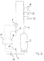
- Figure 1 shows a circuit diagram of a first embodiment of the water supply system according to the invention.
- Figure 2 shows a circuit diagram of a second embodiment of the water supply system according to the invention with return of the circulation line in the cold water line.
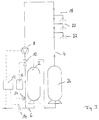
- Figure 3 shows a circuit diagram of a third embodiment of the water supply system according to the invention with two boilers.
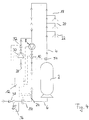
- FIG. 4 shows a circuit diagram of a fourth embodiment of the water supply system according to the invention.
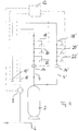
- FIG. 5 shows a circuit diagram of a fifth embodiment with a further circulation line connected in parallel.
- a hot water boiler or boiler 2 which can hold a certain volume of water and heats it by means of an internal heating device.
- the boiler 2 is connected on the output side to a circulation line 4 which is recirculated to the boiler 2.
- connection points for hot water supply lines 18, 20 and 22 are initially provided, through which hot water is removed.
- the circulation line is in the return line behind the connection points for the supply lines 4, a circulation pump 8 is arranged, which is used to circulate the circulation water.
- a solenoid valve 10 is arranged, which serves to close the circulation line. The circulation line flows back into the boiler 2 behind the solenoid valve.
- a cold water line 6 is connected to the inlet side of the boiler 2, through which cold water flows into the boiler 2 after it has been emptied.
- the supply system has the property that immediately after water has been removed from one of the supply lines 18, 20 or 22, the pressure loss transmitted leads to the afterflow of cold water.
- a flow sensor or flow monitor 14 is arranged in the cold water line 6 in front of the connection point of the boiler 2 and serves to detect the flow or flow of the cold water.
- the flow sensor 14 generates a trigger signal when a predetermined limit flow is exceeded, which is transmitted electrically to an electronic timer 12.
- the time switch 12 switches on the circulation pump 8 connected to it.
- the timer 12 opens the solenoid valve 10 connected to it, so that circulation of the circulation water now takes place.
- a delay time is set in the timer 12, which is 1/2 minute to 1 minute. This run-on time elapses after the circulation pump 8 is switched on.
- the circulation pump is switched off and the solenoid valve 10 is closed at the same time. Then the timer 12 is blocked for a certain period of time so that the circulation pump can no longer be switched on during this period.
- the duration is about 1 min.
- the electronic timer 12 has an associated control unit 16 which is only connected to the solenoid valve 10 or a control line to the solenoid valve 10.
- the control unit has the task of keeping the solenoid valve 10 open at a predetermined time of day for a certain period of time, so that a basic circulation takes place during this time due to a gravity flow in the circulation system.
- the control unit 16 thus inhibits a closing pulse of the timer 12, which is given to the solenoid valve 10 by the control line.
- the water supply system works as follows. After opening one of the supply lines 18 to 20, there is a pressure drop in the circulation line 4, which is transmitted directly to the boiler 2. The pressure drop leads to the inflow of cold water through the cold water line 6.
- the flow sensor 14 arranged there detects or measures a flow and generates a trigger signal which is sent directly to the time switch 12 which switches on the circulation pump 8 and opens the solenoid valve 10.
- a pump-driven circulation of the circulation water takes place shortly after the opening of one of the supply lines and provides hot water from the boiler 2 at the connection points for the supply lines 18 to 22 after a short time.
- the cold water initially located in the circulation line below the connection points no longer reaches the supply lines.
- the circulation pump 8 is switched off and the solenoid valve 10 is closed.
- the time required for this corresponds to the run-on time of the timer 12.
- the invention accordingly provides a saving in electricity, since the circulation pump only when water is drawn and only for the necessary Time is running. Furthermore, there is no unnecessary operation of the circulation pump, which in conventional systems leads to the boiler being drained and thus to unnecessary heat loss. This advantage is particularly useful for solar systems because they cannot compensate for the heat loss caused by the circulation at night.
- the second embodiment of the water supply system according to the invention shown in FIG. 2 initially differs from the first embodiment according to FIG. 1 in that the circulation line is not returned to the boiler 2 but to the cold water line 6.
- the junction of the circulation line 4 in the cold water line 6 is located between the flow sensor 14 and the boiler 2. In this way, cooling of the boiler heating water by back-flowing cooled circulation water is avoided immediately.
- a temperature sensor 24, which is connected to the timer 12, is also arranged in the circulation line 4 near the mouth of the cold water line 6. The temperature sensor 24 measures the temperature of the circulation water flowing in the circulation line 4 and supplies the measured value to the timer 12.
- the timer 12 processes the measured value from the temperature sensor 24 in such a way that it switches off the running circulation pump 8 and closes the solenoid valve 10 when the temperature of the circulation water exceeds a predetermined value.
- This limit corresponds to the desired hot water temperature and is around 37 ° C.
- the processing of the measured value in the timer 12 is, however, also dependent on whether a preselectable maximum run-on time has already expired. When this maximum run-on time has expired, the circulation pump 8 is switched off in any case and the solenoid valve 10 is closed in any case.
- the maximum run-on time therefore represents a safety limit for the run-on time for the case that the desired temperature of the circulation water cannot be reached. In this embodiment too, the timer 12 is blocked for a certain period of time after the circulation pump has been switched off, since the circulation water is still hot.
- the third embodiment of the water supply system according to the invention shown in FIG. 3 differs from the embodiment according to FIG. 2 essentially in that a further boiler 26 is arranged in the circulation line 4.
- a double boiler system has the purpose that the first boiler 2 heats the incoming cold water to a preheating temperature with which the water flows into the second boiler 26.
- the heating device arranged in the second boiler 26 now heats the already preheated water by a differential temperature to the desired target temperature.
- the power consumption of the second boiler 26 is therefore lower in comparison than the power consumption of a boiler 2 in an embodiment according to FIG. 2.
- the actual advantage of this arrangement arises when the water in the first boiler 2 of this embodiment is heated by solar energy.
- the boiler 2 is designed, for example, as a solar collector, which preheats the water to, for example, 35 ° C. If such a boiler is equipped with a large volume, for example 500 l, there is the possibility of heat storage even during the night when there is no heating.
- the circulation pump 8 is switched on and the solenoid valve 10 is opened. Due to the pressure difference, preheated water from the first boiler 2 is conveyed to the second boiler 26 and water from the second boiler 26 heated to the desired temperature flows into the circulation line 4 a.
- the temperature sensor 24 in turn ensures that the circulation pump only works until the desired temperature of the circulation water is reached.
- the fourth embodiment of the water supply system according to the invention shown in FIG. 4 differs from the second embodiment shown in FIG. 2 essentially in that a bypass line 28 is connected to the circulation line, which bridges the circulation pump 8 and the solenoid valve 10.
- the bypass line 28 therefore branches off in front of the circulation pump 8 in the flow direction and opens into the circulation line 4 behind the solenoid valve 10 in the flow direction.
- a counter valve 32 configured as a solenoid valve is arranged behind the counter pump 30 and fulfills a function similar to that of the solenoid valve 10.
- the counter pump 30 and the counter valve 32 are connected to the electronic time switch 12. Furthermore, a counter-temperature sensor 34, which is also connected to the electronic time switch 12, is arranged in the circulation line in the vicinity of the outlet from the boiler 2.
- the electronic time switch 12 switches on the counter pump 30 and opens the counter valve 32 if a certain rest period, e.g. 30 seconds has passed in which no water has been removed.
- the activation of the counter pump 30 and the opening of the counter valve 32 leads to the fact that the hot water in the circulation line 4 is conveyed back in the opposite direction to the conveying direction of the circulation pump 8 and is transported back into the boiler 2. In this way it is prevented that the hot water in the circulation line 4 cools down.
- a pump which can be operated in opposite directions is used instead of the circulation pump 8.
- Such a pump can be operated in both directions, for example, by switching four valves.
- a check valve 38 is finally arranged at the entrance of the cold water line 6, which serves to prevent any recoil in the cold water line 6.
- the check valve 38 shuts off.
- a pressure relief valve 36 is connected to the cold water line 6, which opens at an excessive pressure in the cold water line 6.
- FIG. 5 shows a further embodiment of the invention Water supply system with a parallel circulation line 4 'shown.
- This further circulation line 4 ' branches immediately behind the boiler 2 in the direction of flow from the circulation line 4 and opens into the same circulation line 4 in front of the circulation pump 8 again.
- a shut-off valve 10 ' arranged in parallel with the shut-off valve 10' is arranged in the circulation line 4 '.
- the flow sensor 14 'as well as the flow sensor 14 detects a flow or the change in a flow in the circulation line 4' or 4.
- the flow sensor 14 ' is connected to the already mentioned timer 12, which in turn has a control line to the shut-off valve 10' .
- the timer 12 is designed in this embodiment so that it does not detect the flow itself, but a change in the flow in the circulation line 4 '. Since the flow sensor 14 'is arranged in the circulation line, gravity circulation can lead to a basic flow, for example, which should not be interpreted as hot water demand.
- the timer 12 therefore responds only to a positive change, that is to say an increase in the flow in a time interval by a certain amount, in order to switch on the circulation pump 8 and to open the shut-off valve 10 or 10 'located in the corresponding circulation line.
- this embodiment favors a time-controlled gravity circulation only under certain circumstances, since an opening of certain shut-off valves outside of the actual one Demand times can lead to both circulation lines being circulated in another circulation line if there is simultaneous demand, although there is actually only one demand in one circulation line.
- the time-controlled gravity circulation should therefore only be used sparingly and under certain circumstances.
Landscapes
- Engineering & Computer Science (AREA)
- Physics & Mathematics (AREA)
- Thermal Sciences (AREA)
- Chemical & Material Sciences (AREA)
- Combustion & Propulsion (AREA)
- Mechanical Engineering (AREA)
- General Engineering & Computer Science (AREA)
- Domestic Hot-Water Supply Systems And Details Of Heating Systems (AREA)
- Devices For Dispensing Beverages (AREA)
- Gas Separation By Absorption (AREA)
- Massaging Devices (AREA)
- Pipeline Systems (AREA)
Abstract
Description
Die vorliegende Erfindung betrifft ein Wasserversorgungssystem gemäß dem Oberbegriff des Anspruchs 1. Ein derartiges Wasserversorgungssystem ist bereits aus der DE-A-29 45 568 bekannt.The present invention relates to a water supply system according to the preamble of
Herkömmliche Wasserversorgungssysteme sind häufig so aufgebaut, daß einzelne Versorgungsleitungen direkt mit einem Warmwasserkessel verbunden sind. Wenn nach längerer Nichtbenutzung aus den Versorgungsleitungen Warmwasser entnommen werden soll, muß zunächst das in den Versorgungsleitungen befindliche abgekühle Wasser ausfließen. Dies hat den Nachteil, daß das abgekühlte Wasser ungenutzt in das Abwasser fließt und damit verloren geht.Conventional water supply systems are often designed so that individual supply lines are connected directly to a hot water boiler. If hot water is to be drawn from the supply lines after a long period of non-use, the cooled water in the supply lines must first flow out. This has the disadvantage that the cooled water flows unused into the wastewater and is therefore lost.
Zur Lösung dieses Problems ist in der DE-A-29 45 568 bereits eine Zirkulationsleitung vorgeschlagen worden, die mit dem Warmwasserkessel ausgangsseitig verbunden und an einer anderen Stelle in diesen zurückgeführt ist. Die einzelnen Warmwasser-Versorgungsleitungen sind an der Zirkulationsleitung angeschlossen. In der Zirkulationsleitung ist ferner eine Zirkulationspumpe angeordnet, die zu bestimmten Tageszeiten in Gang gesetzt wird, um an den Anschlußstellen der Versorgungsleitungen Warmwasser zur Verfügung zu stellen. Der Nachteil dieser Anordnung liegt darin, daß bei langandauernder Zirkulation des Warmwassers Wärmeverluste im Leitungssystem der Zirkulationsleitung auftreten und die Zirkulationspumpe während des Betriebs Strom verbraucht. Da nur zu bestimmten Zeiten Warmwasser entnommen wird, ist es unnötig, die Zirkulationspumpe über eine längere Zeitdauer zu betreiben. Außerdem lassen sich die Bedarfszeiten nur ungenügend vorhersehen, so daß bei einer unerwarteten Warmwasserentnahme das Wasser in der Zirkulationsleitung bereits abgekühlt ist.To solve this problem, a circulation line has already been proposed in DE-A-29 45 568, the output side with the hot water boiler connected and returned to it at another point. The individual hot water supply lines are connected to the circulation line. A circulation pump is also arranged in the circulation line, which is started at certain times of the day in order to make hot water available at the connection points of the supply lines. The disadvantage of this arrangement is that with long-term circulation of the hot water, heat losses occur in the line system of the circulation line and the circulation pump consumes electricity during operation. Since hot water is only drawn at certain times, it is unnecessary to operate the circulation pump over a longer period of time. In addition, the demand times can only be predicted insufficiently, so that the water in the circulation line has already cooled in the event of unexpected hot water withdrawal.
In der DE-C-37 26 722 ist zwar ein in der Kaltwasserleitung bzw. Zirkulationsleitung angeordneter Durchflußsensor vorhanden. Diese Anordnung hat jedoch den Nachteil, daß aufgrund eines in der Zirkulationsleitung fehlenden Absperrorgans eine fortwährende Schwerkraft-Zirkulation stattfindet. Diese Schwerkraft-Zirkulation entsteht durch Gravitationskräfte, die auf das in der Zirkulationsleitung befindliche Wasser wirken und dieses vermischen bzw. zum Kessel zurücktreiben.In DE-C-37 26 722 there is indeed a flow sensor arranged in the cold water pipe or circulation pipe. However, this arrangement has the disadvantage that, due to the absence of a shut-off element in the circulation line, a continuous gravity circulation takes place. This gravity circulation is created by gravitational forces that act on the water in the circulation line and mix it or drive it back to the boiler.
In einigen veralteten Systemen stellt die Schwerkraft-Zirkulation die einzige Umwälzeinrichtung dar, da eine Pumpe in der Zirkulationsleitung nicht vorgesehen ist. Wenn eine derartige Schwerkraft-Zirkulation unabhängig von Tages- und Nachtzeiten fortwährend stattfindet, wird das Wasser auch während der Nachtstunden umgewälzt, in denen kein Warmwasserbedarf besteht. Die Schwerkraft-Zirkulation bringt daher einen nicht unerheblichen Wärmeverlust mit sich. Bei gewöhnlichen Gebäude-Zirkulationsleitungen, die mit heißem Wasser von einem Kessel versorgt werden, tritt bereits innerhalb von 1 bis 2 Minuten eine erhebliche Abkühlung des Wassers ein.In some obsolete systems, gravity circulation is the only circulator since a pump is in the circulation line is not provided. If such a gravity circulation takes place continuously regardless of day and night times, the water is circulated even during the night when there is no need for hot water. Gravity circulation therefore causes a not inconsiderable loss of heat. With ordinary building circulation pipes that are supplied with hot water from a boiler, the water cools down considerably within 1 to 2 minutes.
Aus der DE-A-33 34 103 ist per se eine durch ein Absperrventil gestenerte Schwerkraft-Zirkulationsleitung bekannt.From DE-A-33 34 103 a gravity circulation line, which is cut by a shut-off valve, is known per se.
Aufgabe der vorliegenden Erfindung ist es daher, eine Wasserversorgungssystem anzugeben, bei dem Wärmeverluste in der Zirkulationsleitung auf ein Mindestmaß reduziert sind.The object of the present invention is therefore to provide a water supply system in which heat losses in the circulation line are reduced to a minimum.
Diese Aufgabe wird gelöst durch ein Wasserversorgungssystem gemäß Anspruch 1.This object is achieved by a water supply system according to
Diese Aufgabe wird ferner gelöst durch ein Wasserversorgungssystem gemäß Anspruch 2, wobei die Zirkulationsleitung in der Kaltwasserleitung mündet. Diese alternative Lösung der erfindungsgemäßen Aufgabe sieht zusätzlich eine Rückführung der Zirkulationsleitung in den Kaltwasser-Zulauf vor, um das zuerst in der Zirkulationsleitung befindliche abgekühlte Wasser zunächst mit Kaltwasser zu vermischen. Bei einigen Systemen ist es günstiger, die Zirkulationsleitung nicht in den Kessel direkt rückzuführen, da das abgekühlte Wasser sich rasch mit dem Warmwasser des Kessels vermischt und dieses abkühlt.This object is further achieved by a water supply system according to
Das Absperrventil hat einerseits die Aufgabe, nach Abschalten der Zirkulationspumpe jede weitere Strömung in der Zirkulationsleitung zu unterbinden, um eine unnötige Schwerkraft-Zirkulation in bedarfsarmen Zwischenzeiten zu verhindern. Zu diesem Zweck kann das Absperrventil geöffnet werden, wenn der Durchfluß in der Kaltwasserleitung einen vorbestimmten Wert überschreitet und das Absperrventil kann geschlossen werden, wenn die Nachlaufzeit abgelaufen ist. Auf diese Weise können auch bei längeren Standzeiten, insbesondere in der Nacht, Wärmeverluste aufgrund der Schwerkraftströmung vermieden werden. Besonders bevorzugt ist das Absperrventil in Strömungsrichtung hinter der Zirkulationspumpe angeordnet. Zum anderen läßt sich mit dem mit dem Zeitschalter und einer Steuereinheit gekoppelten Absperrventil die Schwerkraft-Zirkulation auch steuern. Zu diesem Zweck wird beispielsweise zu Beginn der Hauptbedarfszeit die Schwerkraft-Zirkulation durch Öffnen des Absperrventils eingeschaltet, so daß die Zirkulationsleitung mit geringem Energieverlust vorgewärmt wird. Auf diese Weise ist die Zirkulationsleitung bei Einschaltung der Zirkulationspumpe zu Beginn einer Hauptbedarfszeit bereits vorgewärmt, so daß das zuerst aus dem Kessel in die Zirkulationsleitung gepumpte Wasser kaum abkühlt. Die Wärmeverluste sind bei ausgekühlter Zirkulationsleitung vergleichsweise hoch, so daß auch die Zeitdifferenz zwischen Öffnung eines Verbrauchers und Entnahme von heißem Wasser bei ausgekühlter Zirkulationsleitung höher ist als bei durch Schwerkraft-Zirkulation vorgewärmter Zirkulationsleitung. Erfindungsgemäß läßt sich die Schwerkraft-Zirkulation durch den Zeitschalter beliebig einstellen.On the one hand, the shut-off valve has the task of preventing any further flow in the circulation line after the circulation pump has been switched off, in order to prevent unnecessary gravity circulation in times of low demand. For this purpose, the shut-off valve can be opened when the flow in the cold water line exceeds a predetermined value and the shut-off valve can be closed when the run-on time has expired. In this way, heat losses due to the flow of gravity can be avoided even during long idle times, especially at night. The shut-off valve is particularly preferably arranged in the flow direction behind the circulation pump. On the other hand, gravity circulation can also be controlled with the shut-off valve coupled to the timer and a control unit. For this purpose, for example, at the beginning of the main demand period, the gravity circulation is switched on by opening the shut-off valve, so that the circulation line is preheated with little energy loss. In this way, the circulation line is already preheated when the circulation pump is switched on at the beginning of a main demand period, so that the water first pumped from the boiler into the circulation line hardly cools down. The heat losses are comparatively high when the circulation line is cooled, so that the time difference between the opening of a consumer and the removal of hot water when the circulation line is cooled is higher than in the case of a circulation line preheated by gravity circulation. According to the invention, the gravity circulation can be set as desired by the timer.
Bei der gemäß Anspruch 2 vorgesehenen alternativen Lösung ist die Einmündungsstelle der Zirkulations-Rückleitung in der Kaltwasserleitung zwischen Kessel und Durchflußsensor gelegen, wenn der Durchflußsensor in der Kaltwasserleitung angeordnet ist. Alternativ kann die Zirkulations-Rückleitung an einer beliebigen Stelle der Kaltwasserleitung münden, wenn der Durchflußsensor in der Zirkulationsleitung angeordnet ist.In the alternative solution provided according to
Der Zeitschalter öffnet das Absperrventil, wenn die Strömung in der Kaltwasserleitung bzw. Zirkulationsleitung einen vorbestimmten Wert überschreitet, und schließt, wenn eine einstellbare Nachlaufzeit der Zirkulationspumpe abgelaufen ist. Die vorbestimmte Strömung kann so gewählt werden, daß sie unterhalb der Strömung liegt, die durch einen beliebigen geöffneten Verbraucher im Warmwassernetz ausgelöst wird. Die Grenzströmung kann besonders bevorzugt nahe des Strömungs-Nullpunkts gewählt sein. Besonders bevorzugt ist eine Abstimmung der Öffnung und Schließung des Absperrventils auf den Schaltzustand der Zirkulationspumpe.The timer opens the shut-off valve when the flow in the cold water line or circulation line exceeds a predetermined value and closes when an adjustable run-on time of the circulation pump has expired. The predetermined flow can be chosen so that it is below the flow that is triggered by any open consumer in the hot water network. The limit flow can be selected particularly preferably close to the flow zero point. It is particularly preferred to match the opening and closing of the shut-off valve to the switching state of the circulation pump.
Es ist ferner bevorzugt, daß der Zeitschalter nach Abschaltung der Zirkulationspumpe für eine vorbestimmte Zeitdauer gesperrt ist. Diese Ausgestaltung der Erfindung verhindert, daß die Zirkulationspumpe unmittelbar innerhalb einer kurzen Zeit nach dem Betrieb erneut eingeschaltet wird. Eine derartige Einschaltung ist überflüssig, da das in der Zirkulationsleitung befindliche Wasser noch heiß ist. Innerhalb der vorbestimmten bzw. vorwählbaren Sperrzeit ist daher eine erneute Einschaltung der Zirkulationspumpe verhindert. Eine Öffnung von an der Zirkulationsleitung angeschlossenen Verbrauchern führt daher zu einem Auslösesignal des Durchflußsensors, nicht jedoch zu einer Einschaltung der Zirkulationspumpe, da der Zeitschalter gesperrt ist. Die Sperrzeitdauer beträgt bevorzugt zwischen 30 sek. und 3 min. und besonders bevorzugt zwischen 45 sek. und 1,5 min.It is further preferred that the timer is locked for a predetermined period of time after the circulation pump is switched off. This embodiment of the invention prevents the circulation pump from being switched on again immediately within a short time after operation. Switching on is unnecessary because the water in the circulation line is still hot. A renewed activation of the circulation pump is therefore prevented within the predetermined or preselectable blocking time. An opening of consumers connected to the circulation line therefore leads to a trigger signal of the flow sensor, but not to a switching on of the circulation pump, since the timer is locked. The blocking period is preferably between 30 seconds. and 3 min. and particularly preferably between 45 seconds. and 1.5 min.
Es ist ferner bevorzugt, daß in der Zirkulationsleitung ein mit dem Zeitschalter verbundener Temperaturfühler angeordnet ist, wobei die Nachlaufzeit bei Erreichen einer vorbestimmten Temperatur des Wassers in der Zirkulationsleitung beendet ist. In dieser alternativen Ausgestaltung der Erfindung ist demnach keine vorbestimmte Nachlaufzeit, sondern eine geregelte Nachlaufzeit angegeben. Die Nachlaufdauer der Zirkulationspumpe ist abhängig von dem Aufwärmverhalten des Wassers in der Zirkulationsleitung. Sobald das Wasser eine gewünschte Temperatur erreicht hat, wird ein weiterer Nachlaufbetrieb der Zirkulationspumpe abgebrochen. Der Temperaturfühler ist daher besonders bevorzugt am Ende der Zirkulationsleitung bzw. in Strömungsrichtung hinter der letzten Abzweigstelle einer Verbraucherleitung an der Zirkulationsleitung angeordnet. Sobald ein derartig angeordneter Temperaturfühler die gewünschte Temperatur mißt, ist sichergestellt, daß auch die zuletzt abzweigende Verbraucherleitung mit dem in gewünschter Weise aufgeheizten Wasser versorgt wird.It is further preferred that a temperature sensor connected to the timer is arranged in the circulation line, the run-on time being ended when a predetermined temperature of the water in the circulation line is reached. In this alternative embodiment of the invention, therefore, no predetermined follow-up time, but a regulated follow-up time is specified. The run-on time of the circulation pump depends on the warm-up behavior of the water in the circulation line. As soon as the water has reached a desired temperature, the circulation pump is stopped from operating again. The temperature sensor is therefore particularly preferably arranged at the end of the circulation line or in the flow direction behind the last branch point of a consumer line on the circulation line. As soon as a temperature sensor arranged in this way measures the desired temperature, it is ensured that the consumer line which branches off last is also supplied with the water heated in the desired manner.
In dieser alternativen Ausführungsform ist ergänzend bevorzugt, daß der Zeitschalter die Zirkulationspumpe nach Ablauf einer einstellbaren Maximal-Nachlaufzeit abschaltet, auch wenn die vorbestimmte Temperatur nicht erreicht ist. Mit dieser Ausgestaltung wird sichergestellt, daß die Nachlaufzeit der Pumpe begrenzt wird, wenn aus bestimmten Gründen die gewünschte Temperatur nicht mehr erreichbar ist. Dieser Fall kann beispielsweise eintreten, wenn in Folge eines Ausfalls der Kessel-Stromversorgung kein Warmwasser nachgeliefert werden kann bzw. der Warmwasser-Speicher des Kessels in Folge übermäßiger Entnahme erschöpft ist.In this alternative embodiment, it is additionally preferred that the time switch switches off the circulation pump after an adjustable maximum run-on time has elapsed, even if the predetermined temperature has not been reached. This configuration ensures that the run-on time of the pump is limited when, for certain reasons, the desired temperature can no longer be reached. This can occur, for example, if hot water cannot be supplied as a result of a failure of the boiler power supply or if the hot water tank of the boiler is exhausted as a result of excessive removal.
In einer weiteren Ausführungsform der Erfindung ist in der Zirkulationsleitung ein weiterer Kessel angeordnet. In dieser Ausführungsform werden die Vorteile der erfindungsgemäßen Anordnung deutlich. Wenn zwei Kessel vorgesehen sind, wobei der erste Kessel zur Speisung des zweiten Kessels dient, ist es erforderlich, einen ausreichenden Wasserübergang vom ersten auf den zweiten Kessel sicher zu stellen. Insbesondere in Verbindung mit einer temperaturabhängigen Nachlaufzeit kann sichergestellt werden, daß die Nachlaufzeit ausreicht, um Wasser von dem ersten Kessel zum zweiten Kessel zu fördern und dort aufzuheizen. Wenn der erste Kessel in der Zirkulationsleitung durch Solarenergie gespeist ist, kann die Stromaufnahme des stromgespeisten zweiten Kessels in der Zirkulationsleitung gesenkt werden, wenn das bereits solargewärmte Wasser des ersten Kessels in ausreichender Menge in den zweiten Kessel gelangt. In diesem Fall muß die Heizeinrichtung des zweiten Kessels das Wasser lediglich um die Temperaturdifferenz erwärmen.In a further embodiment of the invention, a further boiler is arranged in the circulation line. The advantages of the arrangement according to the invention become clear in this embodiment. If two boilers are provided, the first boiler serving to feed the second boiler, it is necessary to ensure sufficient water transfer from the first to the second boiler. In particular in connection with a temperature-dependent run-on time, it can be ensured that the run-on time is sufficient to convey water from the first boiler to the second boiler and to heat it up there. If the first boiler in the circulation line is fed by solar energy, the current consumption of the power-fed second boiler in the circulation line can be reduced if the already solar-heated water from the first boiler reaches the second boiler in sufficient quantity. In this case, the heating device of the second boiler only has to heat the water by the temperature difference.
In einer weiteren Ausführungsform der Erfindung ist es ferner bevorzugt, daß mit der Zirkulationsleitung eine Überbrückungsleitung verbunden ist, die die Zirkulationspumpe und das Absperrventil überbrückt, daß in der Überbrückungsleitung eine Gegenpumpe, die in entgegengesetzter Richtung zur Zirkulationspumpe fördert, sowie ein Gegenventil angeordnet sind, die mit dem Zeitschalter verbunden sind, und daß in der Zirkulationsleitung ein mit dem Zeitschalter verbundener Gegen-Temperaturfühler angeordnet ist, wobei die Gegenpumpe durch den Zeitschalter eingeschaltet und bei Erreichen einer vorbestimmten Temperatur in der Zirkulationsleitung oder nach Ablauf einer einstellbaren Maximal-Nachlaufzeit abgeschaltet wird.In a further embodiment of the invention, it is further preferred that a bypass line is connected to the circulation line, which is the circulation pump and the shut-off valve bridges that a counter-pump, which delivers in the opposite direction to the circulation pump, and a counter-valve, which are connected to the time switch, are arranged in the bypass line, and that a counter-temperature sensor connected to the time switch is arranged in the circulation line, wherein the counter pump is switched on by the timer and is switched off when a predetermined temperature in the circulation line is reached or after an adjustable maximum run-on time.
Mit dieser Ausführungsform des erfindungsgemäßen Wasserversorgungssystems wird sichergestellt, daß das in der Zirkulationsleitung nach Abschaltung der Zirkulationspumpe befindliche Heißwasser nicht abkühlt, sondern vor Abkühlung in den Kessel zurückgefördert wird. Das Wasser wird somit durch Rückförderung in den Kessel gegen unerwünschte Abkühlung gesichert. Zu diesem Zweck werden die Gegenpumpe und das Gegenventil nach Ablauf einer vorwählbaren Ruhezeit von dem Zeitschalter eingeschaltet, wodurch das in der Zirkulationsleitung befindliche Leitungswasser in den Kessel zurückgeführt wird und Kaltwasser aus der Kaltwasserleitung in die Zirkulationsleitung einströmt. Zur Begrenzung der Nachlaufzeit und zur Verhinderung einer Abkühlung von Heißwasser im Kessel durch nachströmendes Kaltwasser ist ein Gegen-Temperaturfühler vorgesehen, der mit dem Zeitschalter verbunden ist und bei Unterschreiten einer vorbestimmten Mindesttemperatur die Gegenpumpe ausschaltet und bevorzugt das Gegenventil schließt. Sollte aus irgend einem Grund eine derartige Mindesttemperatur nicht erreichbar sein, so wird die Gegenpumpe nach Ablauf einer einstellbaren Maximal-Nachlaufzeit abgeschaltet, auch wenn die Mindestemperatur nicht erreicht bzw. unterschritten ist. In einer weiterhin bevorzugten Ausführungsform ist die Einschaltung der Gegenpumpe während der Hauptbedarfszeiten des Wasserversorgungssystems gesperrt, um einen abwechselnden Betrieb von Zirkulationspumpe und Gegenpumpe zu verhindern. Während der Hauptbedarfszeiten sollte fortwährend Heißwasser in der Zirkulationsleitung vorhanden sein, um Heißwasser für die in dieser Zeit statistisch häufig auftretenden Entnahmevorgänge bereitzuhalten.With this embodiment of the water supply system according to the invention, it is ensured that the hot water in the circulation line after the circulation pump is switched off does not cool, but is returned to the boiler before cooling. The water is thus secured against unwanted cooling by returning it to the boiler. For this purpose, the counter pump and the counter valve are switched on by the timer after a preselectable idle time, as a result of which the tap water in the circulation line is returned to the boiler and cold water flows from the cold water line into the circulation line. To limit the run-on time and to prevent cooling of hot water in the boiler by cold water flowing in, a counter temperature sensor is provided which is connected to the timer and switches off the counter pump when the temperature falls below a predetermined minimum and preferably closes the counter valve. If for some reason such a minimum temperature cannot be reached, the counter pump is switched off after an adjustable maximum run-on time, even if the minimum temperature has not been reached or fallen below. In a further preferred embodiment, the activation of the counter pump is blocked during the main demand times of the water supply system to prevent alternating operation of the circulation pump and counter pump. During the main times of demand, hot water should be continuously available in the circulation line in order to keep hot water ready for the withdrawal processes that occur statistically frequently during this time.
Es ist ferner bevorzugt, daß bei Anordnung des Durchflußsensors in der Zirkulationsleitung der Zeitschalter so ausgestaltet ist, daß er auf eine vorbestimmte Änderung der Strömung in der Zirkulationsleitung anspricht und die Zirkulationspumpe einschaltet. Bei dieser Ausführungsform ist es wesentlich, daß der Durchflußsensor in der Zirkulationsleitung angeordnet ist, da die Zirkulationsleitung bei eingeschalteter Schwerkraft-Umwälzung eine gewisse Grundströmung aufweist, auf die der Durchflußsensor nicht reagieren darf. Die Höhe dieser Grundströmung ist prinzipiell beliebig. Der Zeitschalter reagiert lediglich auf eine vorbestimmte Änderung der Strömung, d.h. auf einen Differenzenquotienten bzw. Differentialquotienten der Strömung nach der Zeit. Wenn die Strömung kurzzeitig stark zunimmt, ist dies ein Hinweis auf einen zugeschalteten Verbraucher, so daß der Durchflußsensor anspricht und die Zirkulationspumpe einschaltet.It is further preferred that when the flow sensor is arranged in the circulation line, the time switch is designed such that it responds to a predetermined change in the flow in the circulation line and switches on the circulation pump. In this embodiment, it is essential that the flow sensor is arranged in the circulation line since the circulation line has a certain basic flow when the gravity circulation is switched on, to which the flow sensor must not react. The level of this basic flow is in principle arbitrary. The timer only responds to a predetermined change in flow, i.e. to a differential quotient or differential quotient of the flow over time. If the flow increases strongly for a short time, this is an indication of a connected consumer, so that the flow sensor responds and the circulation pump switches on.
Ferner ist in einer weiteren Ausführungsform bevorzugt, daß eine weitere Zirkulationsleitung vorgesehen ist, die hinter dem Kessel von der Zirkulationsleitung abzweigt und in diese zwischen Absperrventil und Zirkulationspumpe einmündet. Die weitere Zirkulationsleitung ist somit mit der Zirkulationsleitung zwischen Kessel und Zirkulationspumpe parallel geschaltet. Diese Ausführungsform empfiehlt sich in großen Gebäuden bei unabhängig voneinander angeordneten und mit unterschiedlichen Bedarfszeiten versehenen Verbrauchergruppen. In einem solchen Fall ist es unwirtschaftlich, eine einzige Zirkulationspumpe für alle Verbrauchergruppen vorzusehen. Die weitere Zirkulationsleitung mündet in Strömungsrichtung vor der Zirkulationspumpe, damit diese für beide Zirkulationsleitungen arbeiten kann. Besonders bevorzugt ist eine Anzahl von weiteren Zirkulationsleitungen vorgesehen.Furthermore, it is preferred in a further embodiment that a further circulation line is provided, which branches off from the circulation line behind the boiler and opens into the latter between the shut-off valve and the circulation pump. The further circulation line is thus connected in parallel with the circulation line between the boiler and the circulation pump. This embodiment is recommended in large buildings with consumer groups arranged independently of one another and provided with different times of use. In such a case, it is uneconomical to provide a single circulation pump for all consumer groups. The further circulation line opens in the direction of flow in front of the circulation pump so that it can work for both circulation lines. A number of further circulation lines are particularly preferably provided.
In dieser Ausführungsform ist es bevorzugt, daß in der weiteren Zirkulationsleitung ein weiterer Durchflußsensor und ein weiteres Absperrventil angeordnet sind, die mit dem Zeitschalter verbunden sind. Auf diese Weise läßt sich der Bedarf in den einzelnen Zirkulationsleitungen durch Messung der Strömung bzw. der Änderung der Strömung separat voneinander erfassen und eine Umwälzung des Zirkulationswassers separat steuern. Die in den Zirkulationsleitungen vorgesehenen Absperrventile lassen auch eine voneinander getrennte Schwerkraft-Zirkulationssteuerung zu.In this embodiment, it is preferred that a further flow sensor and a further shut-off valve are arranged in the further circulation line, which are connected to the timer. In this way, the demand in the individual circulation lines can be determined separately from one another by measuring the flow or the change in the flow, and separately controlling a circulation of the circulation water. The shut-off valves provided in the circulation lines also allow gravity circulation control to be separated from one another.
In dieser Ausführungsform ist es ferner bevorzugt, daß der Zeitschalter in Abhängigkeit von der Strömung in einer der Zirkulationsleitungen das dieser Zirkulationsleitung zugeordnete Absperrventil öffnet und die Zirkulationspumpe einschaltet. Somit wird bei Erfassung einer über einem vorbestimmten Grenzwert liegenden Strömung bzw. einem kurzfristigen Anstieg der Strömung in einer der Zirkulationsleitungen diese Zirkulationsleitung separat und getrennt von den anderen umgewälzt, wobei die in den anderen Zirkulationsleitungen befindlichen Absperrventile geschlossen sind. Eine zeitlich gesteuerte Schwerkraft-Zirkulation in den Zirkulationsleitungen würde jedoch dazu führen, daß bei Einschaltung der Zirkulationspumpe die entsprechend geöffnete Zirkulationsleitung ebenfalls umgewälzt wird. Es ist daher besonders bevorzugt, daß bei dieser Ausführungsform eine zeitlich gesteuerte Schwerkraft-Zirkulation reduziert vorgenommen wird, so daß die Absperrventile überwiegend geschlossen sind.In this embodiment, it is further preferred that the timer, depending on the flow in one of the circulation lines, opens the shut-off valve associated with this circulation line and switches on the circulation pump. Thus, when a flow lying above a predetermined limit value or a short-term increase in the flow in one of the circulation lines is detected, this circulation line is circulated separately and separately from the others, the shut-off valves located in the other circulation lines being closed. However, a time-controlled gravity circulation in the circulation lines would lead to the correspondingly opened circulation line also being circulated when the circulation pump is switched on. It is therefore particularly preferred that, in this embodiment, a time-controlled gravity circulation is carried out in a reduced manner, so that the shut-off valves are mostly closed.
Weitere Vorteile, Merkmale und Anwendungsmöglichkeiten der vorliegenden Erfindung ergeben sich aus der nachfolgenden Beschreibung eines Ausführungsbeispiels in Verbindung mit der Zeichnung.Further advantages, features and possible uses of the present invention result from the following description of an exemplary embodiment in conjunction with the drawing.
Figur 1 zeigt einen Schaltplan einer ersten Ausführungsform des erfindungsgemäßen Wasserversorgungssystems.Figure 1 shows a circuit diagram of a first embodiment of the water supply system according to the invention.
Figur 2 zeigt einen Schaltplan einer zweiten Ausführungsform des erfindungsgemäßen Wasserversorgungssystems mit Rückführung der Zirkulationsleitung in die Kaltwasserleitung.Figure 2 shows a circuit diagram of a second embodiment of the water supply system according to the invention with return of the circulation line in the cold water line.
Figur 3 zeigt einer Schaltplan einer dritten Ausführungsform des erfindungsgemäßen Wasserversorgungssystems mit zwei Kesseln.Figure 3 shows a circuit diagram of a third embodiment of the water supply system according to the invention with two boilers.
Figur 4 zeigt einen Schaltplan einer vierten Ausführungsform des erfindungsgemäßen Wasserversorgungssystems.FIG. 4 shows a circuit diagram of a fourth embodiment of the water supply system according to the invention.
Figur 5 zeigt einen Schaltplan einer fünften Ausführungsform mit einer weiteren parallel-geschalteten Zirkulationsleitung.FIG. 5 shows a circuit diagram of a fifth embodiment with a further circulation line connected in parallel.
Nach Fig. 1 ist Mittelpunkt des Systems der ersten Ausführungsform ein Warmwasser-Kessel bzw. Boiler 2, der ein bestimmtes Volumen an Wasser fassen kann und dieses vermittels einer inwändigen Heizeinrichtung erwärmt. Der Kessel 2 ist ausgangsseitig mit einer Zirkulationsleitung 4 verbunden, die im Kreislauf zu dem Kessel 2 zurückgeführt ist. In Strömungsrichtung des Zirkulationswassers in der Zirkulationsleitung sind zunächst Anschlußstellen für Warmwasser-Versorgungsleitungen 18, 20 und 22 vorgesehen, durch die Warmwasser zur Entnahme gelangt. Hinter den Anschlußstellen für die Versorgungsleitungen ist im Rücklauf der Zirkulationsleitung 4 eine Zirkulationspumpe 8 angeordnet, die zur Umwälzung des Zirkulationswassers dient. In Strömungsrichtung hinter der Zirkulationspumpe ist ein Magnetventil 10 angeordnet, das zum Verschluß der Zirkulationsleitung dient. Hinter dem Magnetventil mündet die Zirkulationsleitung zurück in den Kessel 2.1 is the center of the system of the first embodiment, a hot water boiler or
An der Eingangsseite des Kessels 2 ist eine Kaltwasserleitung 6 angeschlossen, durch die Kaltwasser nach Entleerung des Kessels 2 in diesen einströmt. Das Versorgungssystem hat die Eigenschaft, daß unmittelbar nach Entnahme von Wasser aus einer der Versorgungsleitungen 18, 20 oder 22 der übertragene Druckverlust zum Nachströmen von Kaltwasser führt. In der Kaltwasserleitung 6 ist vor der Anschlußstelle des Boilers 2 ein Durchflußsensor bzw. Durchflußwächter 14 angeordnet, der zur Erfassung des Durchflusses bzw. der Strömung des Kaltwassers dient.A
Der Durchflußsensor 14 erzeugt bei Überschreiten einer vorbestimmten Grenz-Strömung ein Auslösesignal, das elektrisch an einen elektronischen Zeitschalter 12 übertragen wird. Bei Empfang des Auslösesignals schaltet der Zeitschalter 12 die mit ihm verbundene Zirkulationspumpe 8 ein. Ebenfalls bei Empfang des Auslösesignals öffnet der Zeitschalter 12 das mit ihm verbundene Magnetventil 10, so daß nun eine Umwälzung des Zirkulationswasser stattfindet. Im Zeitschalter 12 ist eine Nachlaufzeit eingestellt, die 1/2 Minute bis 1 Minute beträgt. Diese Nachlaufzeit verstreicht nach Einschaltung der Zirkulationspumpe 8. Nach Ablauf der Nachlaufzeit, in der gewöhnlich eine vollständige Umwälzung des Zirkulationswassers stattfindet, wird die Zirkulationspumpe abgeschaltet und gleichzeitig das Magnetventil 10 geschlossen. Sodann wird der Zeitschalter 12 für eine bestimmte Zeitdauer gesperrt, so daß in dieser Zeitdauer die Zirkulationspumpe nicht mehr eingeschaltet werden kann. Die Zeitdauer beträgt etwa 1 min.The
Der elektronische Zeitschalter 12 besitzt eine zugeordnete Steuereinheit 16, die lediglich mit dem Magnetventil 10 bzw. einer Steuerleitung zum Magnetventil 10 verbunden ist. Die Steuereinheit hat die Aufgabe, das Magnetventil 10 zu einer vorgegebenen Tageszeit für eine bestimmte Zeitdauer geöffnet zu halten, so daß in dieser Zeit eine Grundzirkulation aufgrund einer Schwerkraftströmung in dem Zirkulationssystem stattfindet. Somit hemmt die Steuereinheit 16 einen Schließimpuls des Zeitschalters 12, der durch die Steuerleitung an das Magnetventil 10 gegeben wird.The
Das erfindungsgemäße Wasserversorgungssystem arbeitet wie folgt. Nach Öffnung einer der Versorgungsleitungen 18 bis 20 entsteht ein Druckabfall in der Zirkulationsleitung 4, die unmittelbar auf den Kessel 2 übertragen wird. Der Druckabfall führt zum Nachströmen von Kaltwasser durch die Kaltwasserleitung 6. Der dort angeordnete Durchflußsensor 14 erfaßt bzw. mißt eine Strömung und erzeugt ein Auslösesignal, das unmittelbar an den Zeitschalter 12 gegeben wird, welcher die Zirkulationspumpe 8 einschaltet und das Magnetventil 10 öffnet. Dadurch findet kurze Zeit nach Öffnung einer der Versorgungsleitungen eine pumpengetriebene Umwälzung des Zirkulationswassers statt, die schon nach kurzer Zeit aus dem Kessel 2 stammendes Warmwasser an den Anschlußstellen für die Versorgungsleitungen 18 bis 22 bereitstellt. Das zunächst in der Zirkulationsleitung unterhalb der Anschlußstellen befindliche Kaltwasser gelangt nicht mehr in die Versorgungsleitungen. Nach völliger Umwälzung des Zirkulationswassers wird die Zirkulationspumpe 8 abgeschaltet und das Magnetventil 10 geschlossen. Die dafür benötigte Zeit entspricht der Nachlaufzeit des Zeitschalters 12. Die Erfindung liefert demnach eine Stromersparnis, da die Zirkulationspumpe nur bei Wasserentnahme und nur für die notwendige Zeit läuft. Ferner findet kein unnötiger Betrieb der Zirkulationspumpe statt, die bei herkömmlichen Systemen zu einer Entleerung des Boilers und damit zu einem unnötigen Wärmeverlust führt. Dieser Vorteil ist insbesondere bei Solaranlagen von Nutzen, da diese den durch die Umwälzung eintretenden Wärmeverlust in den Nachtzeiten nicht ausgleichen können.The water supply system according to the invention works as follows. After opening one of the
Die in Figur 2 gezeigte zweite Ausführungsform des erfindungsgemäßen Wasserversorgungssystems unterscheidet sich von der ersten Ausführungsform nach Figur 1 zunächst dadurch, daß die Zirkulationsleitung nicht in den Kessel 2 sondern in die Kaltwasserleitung 6 rückgeführt ist. Die Mündungsstelle der Zirkulationsleitung 4 in der Kaltwasserleitung 6 befindet sich zwischen Durchflußsensor 14 und Kessel 2. Auf diese Weise ist eine Abkühlung des Kessel-Heizwassers durch rückströmendes abgekühltes Zirkulationswasser unmittelbar vermieden. In der Zirkulationleitung 4 ist ferner in der Nähe der Mündungsstelle zur Kaltwasserleitung 6 ein Temperaturfühler 24 angeordnet, der mit dem Zeitschalter 12 verbunden ist. Der Temperaturfühler 24 mißt die Temperatur des in der Zirkulationsleitung 4 strömenden Zirkulationswassers und liefert den Meßwert an den Zeitschalter 12. Der Zeitschalter 12 bearbeitet den vom Temperaturfühler 24 stammenden Meßwert derart, daß er die laufende Zirkulationspumpe 8 abschaltet sowie das Magnetventil 10 schließt, wenn die Temperatur des Zirkulationswassers einen vorbestimmten Wert überschreitet. Dieser Grenzwert entspricht der gewünschten Heißwassertemperatur und liegt bei etwa 37°C. Die Verarbeitung des Meßwertes im Zeitschalter 12 ist jedoch auch davon abhängig, ob eine vorwählbare Maximal-Nachlaufzeit schon abgelaufen ist. Bei Ablauf dieser Maximal-Nachlaufzeit wird die Zirkulationspumpe 8 in jedem Fall abgeschaltet und das Magnetventil 10 in jedem Fall geschlossen. Die Maximal-Nachlaufzeit stellt daher eine Sicherheitsgrenze für die Nachlaufzeit für den Fall dar, daß die gewünschte Temperatur des Zirkulationswassers nicht erreichbar ist. Auch in dieser Ausführungsform ist der Zeitschalter 12 nach Abschaltung der Zirkulationspumpe für eine gewisse Zeitdauer gesperrt, da das Zirkulationswasser noch heiß ist.The second embodiment of the water supply system according to the invention shown in FIG. 2 initially differs from the first embodiment according to FIG. 1 in that the circulation line is not returned to the
Die in Figur 3 gezeigte dritte Ausführungsform des erfindungsgemäßen Wasserversorgungssystems unterscheidet sich von der Ausführungsform nach Figur 2 im wesentlichen dadurch, daß in der Zirkulationsleitung 4 ein weiterer Kessel 26 angeordnet ist. Ein derartiges Doppelkessel-System hat den Zweck, daß der erste Kessel 2 das einströmende Kaltwasser auf eine Vorwärmtemperatur aufheizt, mit der das Wasser in den zweiten Kessel 26 strömt. Die im zweiten Kessel 26 angeordnete Heizeinrichtung erwärmt nunmehr das bereits vorgewärmte Wasser um eine Differenztemperatur auf die gewünschte Solltemperatur. Der Stromverbrauch des zweiten Kessels 26 ist daher im Vergleich geringer als der Stromverbrauch eines Kessels 2 bei einer Ausführungsform nach Figur 2. Der eigentliche Vorteil dieser Anordnung stellt sich ein, wenn die Aufwärmung des Wassers im ersten Kessel 2 dieser Ausführungsform durch Solarenergie erfolgt. Zu diesem Zweck ist der Kessel 2 beispielsweise als Sonnenkollektor ausgestaltet, der eine Vorwärmung des Wassers auf beispielsweise 35°C liefert. Wenn ein derartiger Kessel mit einem hohen Fassungsvolumen ausgestattet ist, beispielsweise 500 l, so ergibt sich die Möglichkeit einer Wärmespeicherung auch während der Nachtzeiten, in denen keine Erwärmung stattfindet.The third embodiment of the water supply system according to the invention shown in FIG. 3 differs from the embodiment according to FIG. 2 essentially in that a
Wenn in der Ausführungsform nach Figur 3 ein Wasserbedarf angezeigt wird, wird die Zirkulationspumpe 8 eingeschaltet und das Magnetventil 10 geöffnet. Aufgrund der Druckdifferenz wird vorgewärmtes Wasser des ersten Kessels 2 zum zweiten Kessel 26 gefördert und auf die Solltemperatur aufgeheiztes Wasser des zweiten Kessels 26 strömt in die Zirkulationsleitung 4 ein. Der Temperaturfühler 24 stellt wiederum sicher, daß die Zirkulationspumpe nur bis zum Erreichen der gewünschten Solltemperatur des Zirkulationswassers arbeitet.If a water requirement is indicated in the embodiment according to FIG. 3, the
Die in Figur 4 gezeigte vierte Ausführungsform des erfindungsgemäßen Wasserversorgungssystems unterscheidet sich von der in Figur 2 gezeigten zweiten Ausführungsform im wesentlichen dadurch, daß eine Überbrückungsleitung 28 mit der Zirkulationsleitung verbunden ist, welche die Zirkulationspumpe 8 und das Magnetventil 10 überbrückt. Die Überbrückungsleitung 28 zweigt daher in Strömungsrichtung vor der Zirkulationspumpe 8 ab und mündet in Strömungsrichtung hinter dem Magnetventil 10 in die Zirkulationsleitung 4. In der Überbrückungsleitung 28 ist eine Gegenpumpe 30 angeordnet, die in entgegengesetzter Richtung zur Zirkulationspumpe 8 fördert. In dieser Entgegenförderrichtung ist hinter der Gegenpumpe 30 ein als Magnetventil ausgestaltetes Gegenventil 32 angeordnet, das eine ähnliche Funktion erfüllt wie das Magnetventil 10.The fourth embodiment of the water supply system according to the invention shown in FIG. 4 differs from the second embodiment shown in FIG. 2 essentially in that a
Die Gegenpumpe 30 und das Gegenventil 32 sind mit dem elektronischen Zeitschalter 12 verbunden. Ferner ist in der Zirkulationsleitung in der Nähe des Ausgangs von dem Kessel 2 ein Gegen-Temperaturfühler 34 angeordnet, der ebenfalls mit dem elektronischen Zeitschalter 12 verbunden ist. Der elektronische Zeitschalter 12 schaltet die Gegenpumpe 30 ein und öffnet das Gegenventil 32, wenn außerhalb der Hauptbedarfszeiten des Systems eine gewisse Ruhezeit, bsp. 30 sec. verstrichen ist, in der kein Wasser entnommen wurde. Die Einschaltung der Gegenpumpe 30 und die Öffnung des Gegenventils 32 führt dazu, daß das in der Zirkulationsleitung 4 befindliche Heißwasser in zur Förderrichtung der Zirkulationspumpe 8 entgegengesetzter Richtung zurückgefördert und in den Kessel 2 zurücktransportiert wird. Auf diese Weise wird verhindert, daß das in der Zirkulationsleitung 4 befindliche Heißwasser abkühlt. Bei Betrieb der Gegenpumpe 30 strömt durch die mit der Kaltwasserleitung 6 verbundene Zirkulationsleitung 4 Kaltwasser nach, welches nach und nach die gesamte Zirkulationsleitung 4 ausfüllt. Wenn dieses Kaltwasser den Gegen-Temperaturfühler 34 erreicht, ist das gesamte in der Zirkulationsleitung 4 zuvor befindliche Heißwasser in den Kessel 2 rückgefördert worden und der Zweck der Gegenförderung erreicht. Die Gegenpumpe 30 wird nun bei Unterschreiten einer gewissen Grenztemperatur abgeschaltet und das Gegenventil 32 geschlossen. Ein weiterer Betrieb der Gegenpumpe 30 würde zu einem unerwünschten Eintritt von Kaltwasser in den Kessel 2 und zur Abkühlung desselben führen. Gleichzeitig ist in dem elektronischen Zeitschalter 12 eine Maximal-Nachlaufzeit der Gegenpumpe 30 einstellbar bzw. vorwählbar, so daß eine obere Grenze der Nachlaufzeit angegeben ist, auch wenn die Grenztemperatur aufgrund bestimmter Umstände nicht erreichbar ist.The
Alternativ zur Überbrückungsleitung 28 mit Gegenpumpe 30 und Gegenventil 32 ist es ausreichend, wenn eine in entgegengesetzten Richtungen betreibbare Pumpe anstelle der Zirkulationspumpe 8 eingesetzt wird. Eine derartige Pumpe ist beispielsweise durch Schaltung von vier Ventilen in beiden Richtungen betreibbar.As an alternative to the
In Fig. 4 ist schließlich am Eingang der Kaltwasserleitung 6 ein Rückschlagventil 38 angeordnet, das dazu dient, einen eventuellen Rückstoß in der Kaltwasserleitung 6 zu unterbinden. Wenn das infolge der Erwärmung in Kessel 2 ausgedehnte Warmwasser in die Kaltwasserleitung 6 drückt, sperrt das Rückschlagventil 38 ab. Ferner ist mit der Kaltwasserleitung 6 ein Überdruckventil 36 verbunden, das bei einem übermäßigen Druck in der Kaltwasserleitung 6 aufmacht.In Fig. 4, a
In Fig. 5 ist eine weitere Ausführungsform des erfindungsgemäßen Wasserversorgungssystems mit einer parallel geschalteten weiteren Zirkulationsleitung 4′ gezeigt. Diese weitere Zirkulationsleitung 4′ zweigt unmittelbar hinter dem Kessel 2 in Strömungsrichtung von der Zirkulationsleitung 4 ab und mündet in dieselbe Zirkulationsleitung 4 vor der Zirkulationspumpe 8 wieder ein. In der Zirkulationsleitung 4′ sind abgehend von der Zirkulationsleitung 4 ein Durchflußsensor 14′ sowie Abzweigungsleitungen für Verbraucher 22′, 20′ und 18′ angeordnet. Schließlich ist in der Zirkulationsleitung 4′ ein zum Absperrventil 10 parallel angeordnetes Absperrventil 10′ angeordnet. Der Durchflußsensor 14′ erfaßt ebenso wie der Durchflußsensor 14 eine Strömung bzw. die Veränderung einer Strömung in der Zirkulationsleitung 4′ bzw. 4. Der Durchflußsensor 14′ ist mit dem bereits erwähnten Zeitschalter 12 verbunden, der wiederum eine Steuerleitung zu dem Absperrventil 10′ aufweist. Der Zeitschalter 12 ist bei dieser Ausführungsform so ausgestaltet, daß er nicht die Strömung selbst, sondern eine Änderung der Strömung in der Zirkulationsleitung 4′ erfaßt. Da der Durchflußsensor 14′ in der Zirkulationsleitung angeordnet ist, kann beispielsweise eine Schwerkraft-Zirkulation zu einer Grundströmung führen, die nicht als Warmwasserbedarf zu interpretieren ist. Der Zeitschalter 12 spricht daher lediglich auf eine positive Änderung, d.h. eine Steigerung der Strömung in einem Zeitintervall um einen bestimmten Betrag an, um die Zirkulationspumpe 8 einzuschalten und das in der entsprechenden Zirkulationsleitung befindliche Absperrventil 10 bzw. 10′ zu öffnen. Auf diese Weise wird lediglich das in der Zirkulationsleitung befindliche Zirkulationswasser umgewälzt, in der auch ein tatsächlicher Bedarf vom Zeitschalter 12 erfaßt wurde. Die anderen Zirkulationsleitungen werden infolge geschlossener Absperrventile nicht beeinflußt. Diese Ausführungsform begünstigt jedoch eine zeitlich gesteuerte Schwerkraft-Zirkulation nur unter bestimmten Umständen, da eine öffnung bestimmter Absperrventile außerhalb der eigentlichen Bedarfszeiten dazu führen kann, daß bei gleichzeitigem Bedarf in einer anderen Zirkulationsleitung beide Zirkulationsleitungen umgewälzt werden, obwohl nur in einer Zirkulationsleitung tatsächlich Bedarf besteht. Von der zeitlich gesteuerten Schwerkraft-Zirkulation sollte daher nur unter gewissen Umständen und sparsam Gebrauch gemacht werden.5 shows a further embodiment of the invention Water supply system with a parallel circulation line 4 'shown. This further circulation line 4 'branches immediately behind the
Andererseits ist die zusätzliche Umwälzung bei bereits bestehender Schwerkraft-Zirkulation kein großer Nachteil, da die Schwerkraft-Zirkulation einen grundsätzlichen Bedarf bereits anzeigt. Der Energieverlust ist daher, wenn überhaupt, nicht erheblich.On the other hand, the additional circulation in the case of already existing gravity circulation is not a great disadvantage, since the gravity circulation already indicates a basic need. The energy loss is therefore not significant, if at all.
Claims (10)
- Water supply system comprising
a boiler (2) which on the outlet side thereof is connected to a circulation piping (4) returned to the boiler (2),
a circulation pump (8) arranged in the circulation piping (4),
a cold water piping (6) connected to an inlet side of the boiler, and
a flow sensor (14) provided in the cold water piping (6) and circulation piping (4), respectively and coupled with the circulation pump (8), the flow sensor (14) and the circulation pump (8) being connected by a time switch (12) which turns on the circulation pump (8) in dependence upon flow in the cold water piping (6) and circulation piping (4), respectively and turns off the circulation pump after a run-on period has ended,
characterized in that a shut-off valve (10) coupled with the time switch (12) is provided in the circulation piping (4) and that the shut-off valve (10) is also connected to a control unit (16) which is suitable for opening the shut-off valve for the purpose of a gravity flow. - Water supply system comprising
a boiler (2) which on the outlet side thereof is connected to a circulation piping (4), a circulation pump (8) arranged in the circulation piping (4), a cold water piping (6) connected to an inlet side of the boiler, and
a flow sensor (14) arranged in the cold water piping (6) and circulation piping (4), respectively and coupled with the circulation pump (8), the flow sensor (14) and the circulation pump being connected by a time switch (12) which turns on the circulation pump (8) in dependence upon flow in the cold water piping (6) and circulation piping (4), respectively and turns off the circulation pump after a run-on period has ended,
characterized in that a shut-off valve (10) which is coupled with the time switch (12) is provided in the circulation piping (4), that the circulation piping (4) opens into the cold water piping (6), and that the shut-off valve (10) is also connected to a control unit (16) which is suitable for opening the shut-off valve for the purpose of a gravity flow. - Water supply system according to claim 1 or 2,
characterized in that the time switch (12) is locked for a predetermined time after the circulation pump (8) has been turned off. - Water supply system according to one of the preceding claims, characterized in that a temperature sensor (24) connected to the time switch (12) is arranged in the circulation piping (4), the run-on period coming to an end when a predetermined temperature of the water in the circulation piping (4) is reached.
- Water supply system according to claim 4,
characterized in that after a settable maximum run-on period has ended, the time switch (12) turns off the circulation pump (8), also when the predetermined temperature is not reached. - Water supply system according to one of the preceding claims, characterized in that a further boiler (26) is arranged in the circulation piping.
- Water supply system according to one of the preceding claims, characterized in that a bridging piping (28) is connected to the circulation piping (4) to bridge the circulation pump (8) and the shut-off valve (10), that in the bridging piping (28) there are provided a counter pump (30) feeding in an opposite direction with respect to the the circulation pump (8) and a counter valve (32) both connected to the time switch (12), and that a counter temperature sensor (34) which is connected to the time switch (12) is arranged in the circulation piping (4), the counter pump (30) being turned on by the time switch (12) and being turned off when a predetermined temperature in the circulation piping (4) is reached or after a settable maximum run-on period has ended.
- Water supply system according to claim 1 or 2,
characterized in that a further circulation piping (4′) is provided to branch off the circulation piping (4) downstream of the boiler (2) and to open into the circulation piping between the shut-off valve (10) and the circulation pump (8). - Water supply system according to claim 8,
characterized in that in the further circulation piping (4′) a further flow sensor (14′) and a further shut-off valve (10′) are provided which are connected to the time switch (12). - Water supply system according to claim 8 or 9,
characterized in that in dependence upon flow in one of the circulation pipings (4; 4′) the time switch (12) opens the shut-off valve (10; 10′) which is associated with said circulation piping (4; 4′) and turns on the circulation pump (8).
Applications Claiming Priority (2)
| Application Number | Priority Date | Filing Date | Title |
|---|---|---|---|
| DE4138858A DE4138858C2 (en) | 1991-11-26 | 1991-11-26 | Hot water supply system with a boiler connected to a circulation pipe |
| DE4138858 | 1991-11-26 |
Publications (2)
| Publication Number | Publication Date |
|---|---|
| EP0544207A1 EP0544207A1 (en) | 1993-06-02 |
| EP0544207B1 true EP0544207B1 (en) | 1995-10-18 |
Family
ID=6445617
Family Applications (1)
| Application Number | Title | Priority Date | Filing Date |
|---|---|---|---|
| EP92119900A Expired - Lifetime EP0544207B1 (en) | 1991-11-26 | 1992-11-23 | Water delivery system |
Country Status (3)
| Country | Link |
|---|---|
| EP (1) | EP0544207B1 (en) |
| AT (1) | ATE129333T1 (en) |
| DE (2) | DE4138858C2 (en) |
Cited By (1)
| Publication number | Priority date | Publication date | Assignee | Title |
|---|---|---|---|---|
| EP3372904A1 (en) * | 2017-03-09 | 2018-09-12 | Oliver Kuhnt | Recirculation device |
Families Citing this family (3)
| Publication number | Priority date | Publication date | Assignee | Title |
|---|---|---|---|---|
| EP0626629A3 (en) * | 1993-05-26 | 1995-02-01 | Mendiguren Santiago Eiguren | Control and programming unit for hot water installations. |
| DE4339617C2 (en) * | 1993-11-20 | 2003-06-05 | Vortex Gmbh Dt | Check valve for a domestic water circulation system |
| DE10208772A1 (en) * | 2002-02-28 | 2003-10-02 | Henke Sass Wolf Gmbh | Control device and method for controlling a circulation pump |
Family Cites Families (4)
| Publication number | Priority date | Publication date | Assignee | Title |
|---|---|---|---|---|
| DE2945568A1 (en) * | 1979-11-10 | 1981-05-21 | Wolfgang Dipl.-Phys. Dr.rer.nat. 5100 Aachen Thiele | Hot-water supply system - has discharge detector cutting in circulating pump and connected to timer and regulator |
| DE3334103A1 (en) * | 1983-09-21 | 1985-04-04 | Deutsche Vortex GmbH, 4050 Mönchengladbach | Hot water supply apparatus |
| DE3505191A1 (en) * | 1985-02-15 | 1986-08-21 | Reinhold 6551 Wonsheim Kumpa | Switching system for hot-water supplies |
| US4945942A (en) * | 1989-09-29 | 1990-08-07 | Metlund Enterprises | Accelerated hot water delivery system |
-
1991
- 1991-11-26 DE DE4138858A patent/DE4138858C2/en not_active Expired - Fee Related
-
1992
- 1992-11-23 AT AT92119900T patent/ATE129333T1/en not_active IP Right Cessation
- 1992-11-23 EP EP92119900A patent/EP0544207B1/en not_active Expired - Lifetime
- 1992-11-23 DE DE59204066T patent/DE59204066D1/en not_active Expired - Fee Related
Cited By (2)
| Publication number | Priority date | Publication date | Assignee | Title |
|---|---|---|---|---|
| EP3372904A1 (en) * | 2017-03-09 | 2018-09-12 | Oliver Kuhnt | Recirculation device |
| DE102017104947A1 (en) | 2017-03-09 | 2018-09-13 | Oliver Kuhnt | circulation system |
Also Published As
| Publication number | Publication date |
|---|---|
| DE4138858C2 (en) | 1993-11-25 |
| DE4138858A1 (en) | 1993-05-27 |
| ATE129333T1 (en) | 1995-11-15 |
| DE59204066D1 (en) | 1995-11-23 |
| EP0544207A1 (en) | 1993-06-02 |
Similar Documents
| Publication | Publication Date | Title |
|---|---|---|
| DE2445905B2 (en) | Hot water supply system with thermostatically controlled mixer tap | |
| DE10318821A1 (en) | A hot water system has a storage tank, cold water supply, heating means and multiple tapped outlets with a pumped recirculation of water to provide instant delivery at the outlets | |
| AT409417B (en) | ARRANGEMENT FOR TAKING HOT OR HOT WATER WATER FROM DRINKING WATER QUALITY FROM A HEATING SYSTEM | |
| DE4206074A1 (en) | Arrangement for providing heated water of drinking water quality - has closed water circulation loop to heat take=off water using heat exchanger with pump and valves controlled. | |
| EP0544207B1 (en) | Water delivery system | |
| EP0674137A1 (en) | Hot water supply system with recirculation | |
| DE102006009411B4 (en) | Plant for heating drinking water and killing legionella and other germs | |
| EP1170554A2 (en) | System and method for preparing hot sanitary water | |
| DE3727442C2 (en) | ||
| DE10160763A1 (en) | Coolant circulating device with automatic recovery mechanism | |
| DE19516941C2 (en) | Device and method for controlling the delivery of industrial water | |
| DE19512025C2 (en) | Gas heater | |
| AT377598B (en) | HOT WATER PIPING SYSTEM | |
| DE202006003226U1 (en) | Plant for heating drinking water to kill Legionella and other germs, comprising heated water disinfection circuit, circulating water circuit and preheater-recooler for cooling the hot, disinfected water | |
| EP1553353B1 (en) | Bypass within reaction storage tank supply | |
| DE2846753A1 (en) | METHOD AND DEVICE FOR SWITCHING ON AND OFF A CIRCUIT PUMP OF A HEATING SYSTEM | |
| EP2136146B1 (en) | Device and method for controlling the throughput of solar-operated drinking water flow devices | |
| DE19840962C2 (en) | Installation device for hot water supply to a shower | |
| DE3117771C2 (en) | ||
| EP0346977B1 (en) | Water heater | |
| DE1930950A1 (en) | Self-acting water level regulator that works depending on the current consumption for steam or hot water boilers electrically heated by immersion electrodes | |
| AT397425B (en) | CONTROL PROCEDURE FOR A HEATING SYSTEM | |
| EP3647667B1 (en) | Continuous flow drinking water heater, drinking water heating system and method for operating a continuous flow drinking water heater | |
| DE3005848C2 (en) | ||
| EP3800403B1 (en) | Heating device and method for operating a heating device |
Legal Events
| Date | Code | Title | Description |
|---|---|---|---|
| PUAI | Public reference made under article 153(3) epc to a published international application that has entered the european phase |
Free format text: ORIGINAL CODE: 0009012 |
|
| AK | Designated contracting states |
Kind code of ref document: A1 Designated state(s): AT BE CH DE DK ES FR GB GR IT LI LU MC NL PT SE |
|
| RBV | Designated contracting states (corrected) |
Designated state(s): AT CH DE FR GB IT LI SE |
|
| 17P | Request for examination filed |
Effective date: 19931110 |
|
| 17Q | First examination report despatched |
Effective date: 19940117 |
|
| GRAA | (expected) grant |
Free format text: ORIGINAL CODE: 0009210 |
|
| AK | Designated contracting states |
Kind code of ref document: B1 Designated state(s): AT CH DE FR GB IT LI SE |
|
| PG25 | Lapsed in a contracting state [announced via postgrant information from national office to epo] |
Ref country code: GB Effective date: 19951018 Ref country code: FR Effective date: 19951018 |
|
| REF | Corresponds to: |
Ref document number: 129333 Country of ref document: AT Date of ref document: 19951115 Kind code of ref document: T |
|
| REF | Corresponds to: |
Ref document number: 59204066 Country of ref document: DE Date of ref document: 19951123 |
|
| ITF | It: translation for a ep patent filed |
Owner name: STUDIO ING. ALFREDO RAIMONDI |
|
| PG25 | Lapsed in a contracting state [announced via postgrant information from national office to epo] |
Ref country code: SE Effective date: 19960118 |
|
| EN | Fr: translation not filed | ||
| GBV | Gb: ep patent (uk) treated as always having been void in accordance with gb section 77(7)/1977 [no translation filed] |
Effective date: 19951018 |
|
| PLBE | No opposition filed within time limit |
Free format text: ORIGINAL CODE: 0009261 |
|
| STAA | Information on the status of an ep patent application or granted ep patent |
Free format text: STATUS: NO OPPOSITION FILED WITHIN TIME LIMIT |
|
| 26N | No opposition filed | ||
| PGFP | Annual fee paid to national office [announced via postgrant information from national office to epo] |
Ref country code: CH Payment date: 20050513 Year of fee payment: 13 Ref country code: AT Payment date: 20050513 Year of fee payment: 13 |
|
| PGFP | Annual fee paid to national office [announced via postgrant information from national office to epo] |
Ref country code: DE Payment date: 20050523 Year of fee payment: 13 |
|
| PG25 | Lapsed in a contracting state [announced via postgrant information from national office to epo] |
Ref country code: AT Free format text: LAPSE BECAUSE OF NON-PAYMENT OF DUE FEES Effective date: 20051123 |
|
| PG25 | Lapsed in a contracting state [announced via postgrant information from national office to epo] |
Ref country code: LI Free format text: LAPSE BECAUSE OF NON-PAYMENT OF DUE FEES Effective date: 20051130 Ref country code: CH Free format text: LAPSE BECAUSE OF NON-PAYMENT OF DUE FEES Effective date: 20051130 |
|
| PG25 | Lapsed in a contracting state [announced via postgrant information from national office to epo] |
Ref country code: DE Free format text: LAPSE BECAUSE OF NON-PAYMENT OF DUE FEES Effective date: 20060601 |
|
| REG | Reference to a national code |
Ref country code: CH Ref legal event code: PL |
|
| PGFP | Annual fee paid to national office [announced via postgrant information from national office to epo] |
Ref country code: IT Payment date: 20061130 Year of fee payment: 15 |
|
| PG25 | Lapsed in a contracting state [announced via postgrant information from national office to epo] |
Ref country code: IT Free format text: LAPSE BECAUSE OF NON-PAYMENT OF DUE FEES Effective date: 20071123 |