EP0543552B1 - Anlage zur Extraktion mit Lösungsmittel - Google Patents
Anlage zur Extraktion mit Lösungsmittel Download PDFInfo
- Publication number
- EP0543552B1 EP0543552B1 EP92310257A EP92310257A EP0543552B1 EP 0543552 B1 EP0543552 B1 EP 0543552B1 EP 92310257 A EP92310257 A EP 92310257A EP 92310257 A EP92310257 A EP 92310257A EP 0543552 B1 EP0543552 B1 EP 0543552B1
- Authority
- EP
- European Patent Office
- Prior art keywords
- phase
- plates
- column
- organic phase
- dispersing
- Prior art date
- Legal status (The legal status is an assumption and is not a legal conclusion. Google has not performed a legal analysis and makes no representation as to the accuracy of the status listed.)
- Expired - Lifetime
Links
Images
Classifications
-
- G—PHYSICS
- G21—NUCLEAR PHYSICS; NUCLEAR ENGINEERING
- G21C—NUCLEAR REACTORS
- G21C19/00—Arrangements for treating, for handling, or for facilitating the handling of, fuel or other materials which are used within the reactor, e.g. within its pressure vessel
- G21C19/42—Reprocessing of irradiated fuel
- G21C19/44—Reprocessing of irradiated fuel of irradiated solid fuel
- G21C19/46—Aqueous processes, e.g. by using organic extraction means, including the regeneration of these means
-
- B—PERFORMING OPERATIONS; TRANSPORTING
- B01—PHYSICAL OR CHEMICAL PROCESSES OR APPARATUS IN GENERAL
- B01D—SEPARATION
- B01D11/00—Solvent extraction
- B01D11/04—Solvent extraction of solutions which are liquid
- B01D11/0426—Counter-current multistage extraction towers in a vertical or sloping position
- B01D11/043—Counter-current multistage extraction towers in a vertical or sloping position with stationary contacting elements, sieve plates or loose contacting elements
-
- C—CHEMISTRY; METALLURGY
- C22—METALLURGY; FERROUS OR NON-FERROUS ALLOYS; TREATMENT OF ALLOYS OR NON-FERROUS METALS
- C22B—PRODUCTION AND REFINING OF METALS; PRETREATMENT OF RAW MATERIALS
- C22B60/00—Obtaining metals of atomic number 87 or higher, i.e. radioactive metals
- C22B60/02—Obtaining thorium, uranium, or other actinides
- C22B60/0204—Obtaining thorium, uranium, or other actinides obtaining uranium
- C22B60/0217—Obtaining thorium, uranium, or other actinides obtaining uranium by wet processes
- C22B60/0252—Obtaining thorium, uranium, or other actinides obtaining uranium by wet processes treatment or purification of solutions or of liquors or of slurries
- C22B60/026—Obtaining thorium, uranium, or other actinides obtaining uranium by wet processes treatment or purification of solutions or of liquors or of slurries liquid-liquid extraction with or without dissolution in organic solvents
-
- Y—GENERAL TAGGING OF NEW TECHNOLOGICAL DEVELOPMENTS; GENERAL TAGGING OF CROSS-SECTIONAL TECHNOLOGIES SPANNING OVER SEVERAL SECTIONS OF THE IPC; TECHNICAL SUBJECTS COVERED BY FORMER USPC CROSS-REFERENCE ART COLLECTIONS [XRACs] AND DIGESTS
- Y02—TECHNOLOGIES OR APPLICATIONS FOR MITIGATION OR ADAPTATION AGAINST CLIMATE CHANGE
- Y02E—REDUCTION OF GREENHOUSE GAS [GHG] EMISSIONS, RELATED TO ENERGY GENERATION, TRANSMISSION OR DISTRIBUTION
- Y02E30/00—Energy generation of nuclear origin
- Y02E30/30—Nuclear fission reactors
-
- Y—GENERAL TAGGING OF NEW TECHNOLOGICAL DEVELOPMENTS; GENERAL TAGGING OF CROSS-SECTIONAL TECHNOLOGIES SPANNING OVER SEVERAL SECTIONS OF THE IPC; TECHNICAL SUBJECTS COVERED BY FORMER USPC CROSS-REFERENCE ART COLLECTIONS [XRACs] AND DIGESTS
- Y02—TECHNOLOGIES OR APPLICATIONS FOR MITIGATION OR ADAPTATION AGAINST CLIMATE CHANGE
- Y02W—CLIMATE CHANGE MITIGATION TECHNOLOGIES RELATED TO WASTEWATER TREATMENT OR WASTE MANAGEMENT
- Y02W30/00—Technologies for solid waste management
- Y02W30/50—Reuse, recycling or recovery technologies
Definitions
- This invention relates to means for carrying out solvent extraction procedures employing countercurrent flow of streams of an aqueous phase and an organic phase while passing through a fluid contacting extraction column followed by a stripping column.
- the invention particularly relates to the so-called "Purex Process" for recovering uranium from waste or spent material containing unwanted contaminants, such as scrap from fissionable nuclear fuel manufacturing or processing, and spent fissionable nuclear fuel from use in a nuclear reactor.
- Purx Process for recovering uranium from waste or spent material containing unwanted contaminants, such as scrap from fissionable nuclear fuel manufacturing or processing, and spent fissionable nuclear fuel from use in a nuclear reactor.
- the Purex Process consists of a sequence of chemical steps or operations comprising initially treating the waste of scrap material or spent fuel containing uranium compounds with an aqueous solution of nitric acid (HNO 3 ), and thereby dissolving the uranium to produce uranyl nitrate (UO 2 (NO 3 ) 2 ) and other acid soluble components within an aqueous phase.
- HNO 3 nitric acid
- UO 2 (NO 3 ) 2 uranyl nitrate
- This aqueous phase containing the acid dissolved components including uranyl nitrate, and any acid insoluble components of the waste is passed down through an extraction column while an organic phase of tri-butyl phosphate in an organic diluent of a paraffinic mixture such as kerosene is passed up through the extraction column in counter-current flow with the aqueous phase.
- the soluble uranium compounds comprising uranyl nitrate of the aqueous phase are extracted therefrom by the organic phase and combined with the tri-butyl phosphate. This separates the uranium and carries it within the organic phase from the extraction column.
- the aqueous phase, and the organic phase each exit from the extraction column at opposite ends from each other and from their respective entries, the aqueous phase with the acid soluble raffinate contaminants and the organic phase with the separated uranium.
- the organic phase effluent from the extraction column carrying the separated uranium compounds is then passed up through a stripping column while water is passed down through the stripping column in counter-current flow with the organic phase.
- the water releases the uranium from the tri-butyl phosphate of the organic phase whereby it is transferred to and carried within the aqueous phase.
- the aqueous phase, and the organic phase each exit from the stripping column at opposite ends from each other and from their respective entries, the aqueous phase containing the uranium compounds for recovery separated from contaminants.
- the organic phase is then recycled back through the extraction column.
- the procedure is carried out with a continuous flow of all components through the system comprising the extraction column and stripping column.
- the columns are typically agitated by either pulse pumps or reciprocating plates to permit optimal droplet formation and coalescence on each plate.
- the agitation is most commonly referred to as mixing energy. Excessive mixing energy or flow rates can cause flooding, a condition which precludes flow of one or both liquid operating mode phases in the column due mainly to coalescence of small droplets into larger droplets. Mixing energy is critical to efficiency of the extraction column and helps establish a characteristic uranium profile.
- This invention comprises an apparatus providing improved total production throughput of the two liquid phases and their separating effectiveness in pulsed solvent extraction processes employing countercurrent flow of streams of an aqueous phase and an organic phase.
- the apparatus responsible for such improved functioning comprises a contouring of fluid passing orifices in the phase dispensing perforated plates utilized in conventional extraction columns.
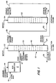
- a typical solvent extraction and purification system 10 such as the Purex process for the recovery of uranium, for example, comprises an acid dissolving vessel 12 provided with a source of waste material 14 containing uranium compounds and a supply of nitric acid (HNO 3 ) 16 in an aqueous medium.
- Uranium contents of the waste material, along with any other nitric acid soluble components, are dissolved with the nitric acid in vessel 12, converting the uranium compounds into water soluble uranyl nitrate.
- This aqueous phase of weak acid containing any nitric acid soluble components of the waste and the soluble components including the uranyl nitrate are fed through a feed inlet 18 into the upper portion of an extraction column 20.
- this aqueous phase from vessel 12 is filtered before feeding into extraction column 20.
- the aqueous phase containing any nitric acid soluble components including uranyl nitrate and soluble components, fed into the extraction column 20, through feed inlet 22, flows downward within the column while an organic phase is fed through a feed inlet 24 into the lower portion of the extraction column 20 and flows upward within the column counter-current to the down flowing aqueous phase.
- the organic solvent phase containing tri-butyl phosphate and an organic diluent, upon making counter-flowing contact with the extraction column with the aqueous phase, separates the uranium by means of the tri-butyl phosphate chemically combining with the uranium oxide ++ ions dissolved in the aqueous phase while excluding soluble impurities.
- the insoluble impurities are carried downward in the aqueous phase to an outlet 26 in the lower portion of the extraction column 20 for soluble raffinate.
- the organic phase of tri-butyl phosphate combined with uranium and the organic diluent flows upward to an extract outlet 28 in the upper portion of the extraction column 20.
- the organic phase containing the uranium combined with the tri-butyl phosphate and organic diluent is conveyed through a duct to an inlet 30 in the lower portion of a stripping column 32.
- Water is fed into the upper portion of the stripper column 32 through inlet 34 for flow downward through the column countercurrent to the upward flow of the organic phase entering in a lower portion.
- the water contacting the organic phase in counter flow within the stripping column 32 releases the water soluble uranium compounds from the tri-butyl phosphate and organic phase, and the water containing the separated uranyl nitrate product is discharged from the column through an outlet 36 in its lower portion.
- An organic phase outlet 38 for the organic solvent in the upper portion of stripping column 32 discharges the organic solvent into a duct which is in fluid communication with the organic phase inlet 24 for recycling the organic solvent comprising the tri-butyl phosphate and organic diluent for reuse.
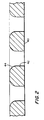
- the countercurrent flow solvent extraction systems utilize columns provided with a multiplicity of phase dispensing perforated plates 40 traversing the column intermediate the upper area and lower area fluid connections for the entry or discharge of the counter-current flowing liquids.
- Phase dispensing plates 40 are provided with a plurality of fluid passing orifices 42, or nozzles passing therethrough as shown enlarged in Figure 2.
- Plates 40 typically are of a thickness in the range of about 0.0508 cm (0.020 inch) up to about 0.635 cm (0.25 inch), and orifices 42 typically are of a diameter in the range of about 0.318 cm (0.125 inch) to about 0.635 cm (0.25 inch). For example, approximately 0.059 cm (0.022 inch) for stainless steel plates and approximately 0.635 cm (0.25 inch) for teflon plates.
- the function of a pulsed, solvent extraction column in countercurrent flow aqueous/organic phase solvent extraction processes is to disperse either the aqueous or the organic phase into small droplet sizes in the other phase as the continuous medium.
- Small droplet size of a phase increases the surface area per unit volume of the dispersed phase whereby the rate of mass transfer of the desired component for extraction from one of the phases to the other is in turn increased.
- the phenomenon of droplet coalescence within solvent extraction columns limits the overall mass transfer rate whereupon the separation efficiency along with the total throughput rate of the countercurrent aqueous and solvent flow streams is retarded.
- droplet diameters increase, the holdup of the dispersed phase or fractional volume of the dispersed phase increases. Large droplet diameters and increased holdup lead to flooding, the effect of the aqueous and organic solvent phases leaving the extraction column together through the organic solvent phase outlet.
- Droplets of the dispersed phase form in the extraction column as the dispersed liquid exits from the fluid passing orifices in the phase dispersing perforated plates. Without pulsation the continuous laminar flow through the orifices produces droplet sizes equal to or great than the diameter of the orifice or nozzle throat. In a pulsed column the dynamic forces due to turbulent eddies formed at the exit of the orifice or nozzle break up the drops in opposition to interfacial forces.
- the mechanical action of the pulsating flow produces turbulent eddies that reduce the diameter of the droplets formed at the exit of the fluid passing orifices, or nozzles in the phase dispersing plates.
- the dispersed droplets are a factor of 3 to 5 smaller than the orifice or nozzle diameter.
- the droplet diameter is equal to or greater than the orifice or nozzle diameter. Accordingly, the improved mass transfer rates an total throughput attained with the small droplet size have lead to the use of pulsed columns, where significant component separation is required.
- the droplets tend to coalesce within the continuous phase in the region where the streamlines converge or diverge from the solid boundary forming larger droplets, thereby limiting the total throughput and separating efficiency.
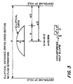
- the fluid passing orifices 42, or nozzles in the phase dispersing perforated plates 40 are provided with their upper peripheral edge 44 rounded in an elliptical contour as shown in Figure 2 of the drawing.
- Phase dispersing plates 40 as employed in this invention should be constructed of material depending upon whether or not the organic or aqueous phase is dispersed within the other. This is, when the aqueous phase is dispersed and this organic phase is continuous, the plates 40 and the column should be constructed from non-wetting materials or plastics such as teflon. This prevents the droplets of the aqueous phase from wetting the plates 40 or column surface on contact.
- the plates 40 and column materials can be either metal such as stainless steel or glass. Then the organic droplets will not wet the plates 40 or column surfaces.
Claims (7)
- Säule (20) zur Lösungsmittelextraktion mit entgegengesetzten Strömen aus einer wässerigen Phase und einer organischen Phase, einem Einlaß (22) für die wässerige Phase und einem Auslaß (28) für den Extrakt der organischen Phase, die in einem oberen Bereich der Säule angeordnet sind, einem Auslaß (26) für unlösliches Raffinat und einem Einlaß (24) für organische Phase, die in einem unteren Bereich davon angeordnet sind, sowie phasen-zerstreuenden, perforierten Platten (40), die die Säule zwischen dem Einlaß der wässerigen Phase im oberen Bereich und dem Einlaß der organischen Phase im unteren Bereich durchqueren und in eine Strömung dazwischen eingreifen, wobei die perforierten Platten eine Vielzahl von Strömungsmittel durchlassenden, durchgehenden Öffnungen (42) aufweisen, die dadurch charakterisiert sind, daß ihre obere, periphere Kante (44) in einer elliptischen Kontur abgerundet ist, um das Zusammenlaufen von passierenden Phasentröpfchen zu verringern.
- Vorrichtung nach Anspruch 1, worin die Mehrzahl der Strömungsmittel durchlassenden Öffnungen (42) in den phasen-zerstreuenden Platten (40) einen Durchmesser im Bereich von etwa 0,318 bis etwa 0,635 cm (0,125 bis etwa 0,25 inches) hat.
- Vorrichtung nach Anspruch 1, worin die phasen-zerstreuenden Platten (40) eine Dicke im Bereich von etwa 0,0508 bis etwa 0,635 cm (0,020 bis etwa 0,25 inches) aufweisen.
- Vorrichtung nach Anspruch 1, worin die phasen-zerstreuenden Platten (40) aus einem nicht benetzenden Kunststoffmaterial zusammengesetzt sind.
- Vorrichtung nach Anspruch 1, worin die phasen-zerstreuenden Platten (40) aus einem nicht benetzenden TEFLON-Polytetrafluorethylenharz zusammengesetzt sind.
- Vorrichtung nach Anspruch 1, worin die phasen-zerstreuenden Platten (40) aus korrosionsbeständigem Stahl zusammengesetzt sind.
- Vorrichtung nach Anspruch 1 mit einer Vielzahl phasen-zerstreuender, perforierter Platten (40) einer Dicke im Bereich von etwa 0,0508 bis etwa 0,635 cm (0,020 bis etwa 0,25 inches), durch die eine Vielzahl von Strömungsmittel durchlassenden Öffnungen (42) eines Durchmessers im Bereich von etwa 0,318 bis etwa 0,635 cm (0,125 bis etwa 0,25 inches) hindurchgeht, deren obere, periphere Kante (44) in einer elliptischen Kontur abgerundet ist, die definiert ist durch die Formel:

Applications Claiming Priority (2)
| Application Number | Priority Date | Filing Date | Title |
|---|---|---|---|
| US793926 | 1985-11-01 | ||
| US07/793,926 US5219533A (en) | 1991-11-18 | 1991-11-18 | Apparatus for solvent extraction process |
Publications (2)
| Publication Number | Publication Date |
|---|---|
| EP0543552A1 EP0543552A1 (de) | 1993-05-26 |
| EP0543552B1 true EP0543552B1 (de) | 1996-10-02 |
Family
ID=25161178
Family Applications (1)
| Application Number | Title | Priority Date | Filing Date |
|---|---|---|---|
| EP92310257A Expired - Lifetime EP0543552B1 (de) | 1991-11-18 | 1992-11-10 | Anlage zur Extraktion mit Lösungsmittel |
Country Status (5)
| Country | Link |
|---|---|
| US (1) | US5219533A (de) |
| EP (1) | EP0543552B1 (de) |
| JP (1) | JP3316007B2 (de) |
| DE (1) | DE69214253D1 (de) |
| TW (1) | TW216467B (de) |
Cited By (1)
| Publication number | Priority date | Publication date | Assignee | Title |
|---|---|---|---|---|
| EP2886175A1 (de) | 2013-12-18 | 2015-06-24 | Sulzer Chemtech AG | Statisches Internum, Verwendung eines oder mehrerer statischer Interna, erregter Flüssig-Flüssig-Extraktor und Verwendung eines erregten Flüssig-Flüssig-Extraktors |
Families Citing this family (11)
| Publication number | Priority date | Publication date | Assignee | Title |
|---|---|---|---|---|
| JP2515009B2 (ja) * | 1989-01-13 | 1996-07-10 | 株式会社東芝 | 不揮発性半導体メモリの製造方法 |
| US5419880A (en) * | 1993-10-08 | 1995-05-30 | Falconbridge, Ltd. | Controlled acid-strong acid strip process |
| AU6844396A (en) * | 1995-09-18 | 1997-04-09 | Koch (Cyprus) Limited | Agitated-packed extraction column |
| CZ290229B6 (cs) * | 1995-12-15 | 2002-06-12 | Bayer Aktiengesellschaft | Vícefázový extraktor |
| GB9722930D0 (en) * | 1997-10-31 | 1998-01-07 | British Nuclear Fuels Plc | Nuclear fuel reprocessing |
| FR2905283B1 (fr) * | 2006-08-31 | 2009-04-17 | Commissariat Energie Atomique | Procede et dispositif de precipitation d'un solute |
| FR2931815B1 (fr) * | 2008-05-30 | 2010-08-20 | Sarl Firmus | Procede ameliore de separation des composes presents dans une phase aqueuse continue d'un effluent a traiter, notamment petrochimique par inversion de phase. |
| WO2011045382A1 (en) * | 2009-10-16 | 2011-04-21 | Novartis Ag | Method and device for maintaining a concentration of a treatment bath |
| WO2011045380A1 (en) | 2009-10-16 | 2011-04-21 | Novartis Ag | Apparatus and method for transporting contact lenses through dipping baths |
| US9308470B2 (en) | 2013-03-12 | 2016-04-12 | The Chem-Pro Group Llc | Liquid-liquid extractor |
| CN111349789B (zh) * | 2020-04-24 | 2021-08-17 | 核工业北京化工冶金研究院 | 一种具有多出口设计的碱渣浸出液铀纯化方法 |
Family Cites Families (9)
| Publication number | Priority date | Publication date | Assignee | Title |
|---|---|---|---|---|
| US2191919A (en) * | 1936-01-21 | 1940-02-27 | Sinclair Refining Co | Art of refining |
| GB688837A (en) * | 1950-02-22 | 1953-03-18 | Nat Res Developmfnt Corp | Improvements in or relating to packings for vessels in which fluids are contacted |
| US2784953A (en) * | 1953-10-02 | 1957-03-12 | Exxon Research Engineering Co | Means for contacting fluids |
| US3632315A (en) * | 1968-10-23 | 1972-01-04 | Universal Oil Prod Co | Liquid-liquid contacting tray system |
| US3854176A (en) * | 1971-09-29 | 1974-12-17 | Atlantic Richfield Co | High capacity geometrically-favorable solvent extraction columns for processing fissile materials |
| US4429049A (en) * | 1982-02-22 | 1984-01-31 | Mead Corporation | Method for the analysis of organic pollutants |
| JPS59147296A (ja) * | 1983-02-14 | 1984-08-23 | 日本原子力研究所 | 核燃料・核原料球状粒子の製造方法および原料ゾルのゲル化装置 |
| GB2173417B (en) * | 1985-04-12 | 1989-01-11 | Atomic Energy Authority Uk | Liquid-liquid extraction columns |
| DE8529714U1 (de) * | 1985-10-19 | 1985-11-28 | Bayer Ag, 5090 Leverkusen | Verfahrenstechnische Packung mit Randabdichtung zur Flüssig-Flüssig-Extraktion |
-
1991
- 1991-11-18 US US07/793,926 patent/US5219533A/en not_active Expired - Fee Related
-
1992
- 1992-08-18 TW TW81106508A patent/TW216467B/zh active
- 1992-11-09 JP JP29849092A patent/JP3316007B2/ja not_active Expired - Fee Related
- 1992-11-10 EP EP92310257A patent/EP0543552B1/de not_active Expired - Lifetime
- 1992-11-10 DE DE69214253T patent/DE69214253D1/de not_active Expired - Lifetime
Cited By (1)
| Publication number | Priority date | Publication date | Assignee | Title |
|---|---|---|---|---|
| EP2886175A1 (de) | 2013-12-18 | 2015-06-24 | Sulzer Chemtech AG | Statisches Internum, Verwendung eines oder mehrerer statischer Interna, erregter Flüssig-Flüssig-Extraktor und Verwendung eines erregten Flüssig-Flüssig-Extraktors |
Also Published As
| Publication number | Publication date |
|---|---|
| DE69214253D1 (de) | 1996-11-07 |
| US5219533A (en) | 1993-06-15 |
| EP0543552A1 (de) | 1993-05-26 |
| JP3316007B2 (ja) | 2002-08-19 |
| JPH05212206A (ja) | 1993-08-24 |
| TW216467B (de) | 1993-11-21 |
Similar Documents
| Publication | Publication Date | Title |
|---|---|---|
| EP0543552B1 (de) | Anlage zur Extraktion mit Lösungsmittel | |
| US7507343B2 (en) | Mixing and settling method and device in solvent extraction processes to recover high-purity products | |
| US4221658A (en) | Effecting liquid-liquid contact | |
| Lee et al. | Continuous extraction of penicillin G by an emulsion liquid membrane in a countercurrent extraction column | |
| US20180282887A1 (en) | Solvent extraction and stripping system | |
| US5662861A (en) | Liquid extraction | |
| EP2906315B1 (de) | Flüssig-flüssig-extraktionssystem und verfahren zu dessen verwendung | |
| US4161439A (en) | Apparatus for application of electrostatic fields to mixing and separating fluids | |
| DE2518846A1 (de) | Verfahren und vorrichtung zur phasentrennung in solvent-extraktionsverfahren | |
| JPH0113896B2 (de) | ||
| US3293004A (en) | Process for solvent extraction stripping | |
| JP2001029703A (ja) | セトラー、湿式銅製錬装置用の抽出器及びストリッパ | |
| US4565672A (en) | Method for the manufacture of PuO2 -containing crystals | |
| US5132016A (en) | Solvent prestripping in a zr/hf separation liquid-liquid extraction (llx) circuit | |
| JPS61245801A (ja) | 向流抽出用の目皿塔 | |
| US5641462A (en) | Continuous solvent extraction with bottom gas injection | |
| CN112538570A (zh) | 一种基于浮游萃取系统分离稀贵金属的方法 | |
| US3718319A (en) | Apparatus and process for contacting immiscible liquids | |
| US3089750A (en) | Recovery of values from ores by use of electric fields | |
| Valsaraj et al. | Nonfoaming adsorptive bubble separation processes | |
| AU684101B2 (en) | Improvements in or relating to liquid extraction | |
| EP0277422A2 (de) | Chemische Behandlung von Likören | |
| Abdumannonovich et al. | Development Of High-Efficiency Extraction Equipment And Prospects For Industrial Application Of Extractors With Pneumatic Fluid Mixing | |
| GB2110868A (en) | Dissolution of solids such as solid nuclear reactor fuels | |
| US4288412A (en) | Post treatment method for the recovery of uranium from wet-process phosphoric acid |
Legal Events
| Date | Code | Title | Description |
|---|---|---|---|
| PUAI | Public reference made under article 153(3) epc to a published international application that has entered the european phase |
Free format text: ORIGINAL CODE: 0009012 |
|
| AK | Designated contracting states |
Kind code of ref document: A1 Designated state(s): DE ES FR GB IT |
|
| 17P | Request for examination filed |
Effective date: 19931102 |
|
| 17Q | First examination report despatched |
Effective date: 19950111 |
|
| GRAH | Despatch of communication of intention to grant a patent |
Free format text: ORIGINAL CODE: EPIDOS IGRA |
|
| GRAH | Despatch of communication of intention to grant a patent |
Free format text: ORIGINAL CODE: EPIDOS IGRA |
|
| GRAG | Despatch of communication of intention to grant |
Free format text: ORIGINAL CODE: EPIDOS AGRA |
|
| GRAA | (expected) grant |
Free format text: ORIGINAL CODE: 0009210 |
|
| AK | Designated contracting states |
Kind code of ref document: B1 Designated state(s): DE ES FR GB IT |
|
| PG25 | Lapsed in a contracting state [announced via postgrant information from national office to epo] |
Ref country code: IT Free format text: LAPSE BECAUSE OF FAILURE TO SUBMIT A TRANSLATION OF THE DESCRIPTION OR TO PAY THE FEE WITHIN THE PRESCRIBED TIME-LIMIT;WARNING: LAPSES OF ITALIAN PATENTS WITH EFFECTIVE DATE BEFORE 2007 MAY HAVE OCCURRED AT ANY TIME BEFORE 2007. THE CORRECT EFFECTIVE DATE MAY BE DIFFERENT FROM THE ONE RECORDED. Effective date: 19961002 Ref country code: FR Effective date: 19961002 Ref country code: ES Free format text: THE PATENT HAS BEEN ANNULLED BY A DECISION OF A NATIONAL AUTHORITY Effective date: 19961002 |
|
| REF | Corresponds to: |
Ref document number: 69214253 Country of ref document: DE Date of ref document: 19961107 |
|
| PG25 | Lapsed in a contracting state [announced via postgrant information from national office to epo] |
Ref country code: GB Effective date: 19970102 |
|
| PG25 | Lapsed in a contracting state [announced via postgrant information from national office to epo] |
Ref country code: DE Effective date: 19970103 |
|
| EN | Fr: translation not filed | ||
| PLBE | No opposition filed within time limit |
Free format text: ORIGINAL CODE: 0009261 |
|
| STAA | Information on the status of an ep patent application or granted ep patent |
Free format text: STATUS: NO OPPOSITION FILED WITHIN TIME LIMIT |
|
| GBPC | Gb: european patent ceased through non-payment of renewal fee |
Effective date: 19970102 |
|
| 26N | No opposition filed |