EP0543365B1 - Elektronischer Wattstundenzähler - Google Patents
Elektronischer Wattstundenzähler Download PDFInfo
- Publication number
- EP0543365B1 EP0543365B1 EP92119709A EP92119709A EP0543365B1 EP 0543365 B1 EP0543365 B1 EP 0543365B1 EP 92119709 A EP92119709 A EP 92119709A EP 92119709 A EP92119709 A EP 92119709A EP 0543365 B1 EP0543365 B1 EP 0543365B1
- Authority
- EP
- European Patent Office
- Prior art keywords
- voltage
- proportional
- current
- magneto
- load
- Prior art date
- Legal status (The legal status is an assumption and is not a legal conclusion. Google has not performed a legal analysis and makes no representation as to the accuracy of the status listed.)
- Expired - Lifetime
Links
- 238000006243 chemical reaction Methods 0.000 claims description 55
- 230000005355 Hall effect Effects 0.000 description 2
- 230000006866 deterioration Effects 0.000 description 2
- 239000004020 conductor Substances 0.000 description 1
- 238000001514 detection method Methods 0.000 description 1
- 238000010586 diagram Methods 0.000 description 1
- 239000007924 injection Substances 0.000 description 1
- 238000002347 injection Methods 0.000 description 1
- 230000000704 physical effect Effects 0.000 description 1
- 239000002887 superconductor Substances 0.000 description 1
Images

Classifications
-
- G—PHYSICS
- G01—MEASURING; TESTING
- G01R—MEASURING ELECTRIC VARIABLES; MEASURING MAGNETIC VARIABLES
- G01R21/00—Arrangements for measuring electric power or power factor
- G01R21/08—Arrangements for measuring electric power or power factor by using galvanomagnetic-effect devices, e.g. Hall-effect devices
Definitions
- the present invention relates to an electronic watthour meter comprising a first magneto-electric conversion element to which a current proportional to a load voltage and a magnetic field proportional to a load current are supplied for producing a voltage proportional to the load power given by the load voltage and the load current.
- Such a watthour meter is described in EP-A-0 322 802 and contains a multiplication-adding circuit with a current output, a current-frequency converter comprising a compensation circuit to compensate the ripple, offset and charge injections of electronic switches, and means that remove an offset voltage component contained in the output of the magneto-electric conversion element.
- the directions of current supplied to the respective Hall-elements of the multiplication adding circuit are reversed and then the outputs of the respective Hall-elements corresponding to the directions of current are added without reversing the direction of magnetic field, so that the output of the multiplication adding circuit is fed to the current frequency converter.
- the outputs of the current frequency converter are fed back through the compensation circuit and used for the compensation of an offset component.
- a further conventional electronic watthour meter is disclosed, for example, in Japanese Patent Publications Nos. 59-53508/1984 corresponding to JP-A-53 115 157 and 60-54704/1985 corresponding to JP-A-54 000 548.
- This electronic watthour meter comprises an auxiliary voltage transformer for producing a voltage output signal proportional to a load voltage of a distribution line, an auxiliary current transformer for producing a current output signal proportional to a consumed current, a power-voltage conversion circuit for multiplying the voltage output signal and the current output signal from the auxiliary voltage transformer and the auxiliary current transformer to produce an output voltage proportional to a load power, a voltage-frequency conversion circuit supplied from the power-voltage conversion circuit with the output voltage proportional to the load power for integrating the output voltage to produce a pulse signal, a frequency dividing circuit for weighting the pulse signal from the voltage-frequency conversion circuit to produce a divided pulse signal proportional to electric power, and a display circuit responsive to the divided pulse signal from the frequency dividing circuit for displaying
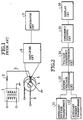
- Fig. 1 shows a structure of the power-voltage conversion circuit including a Hall element (Hall-effect element) as a magneto-electric conversion element.
- an auxiliary voltage transformer 1 produces a voltage output signal proportional to a load voltage.
- the voltage output signal from the auxiliary voltage transformer 1 is converted through a resistor 2 into a current i which is supplied to a Hall element 3.
- a consumed current supplied to an auxiliary current transformer flows through a primary conductor 5 wound around a core 4 to produce a magnetic field proportional to the consumed current.
- the magnetic field is applied to the Hall element 3.
- the voltage Vop produced by the Hall element 3 has a low level. As shown in Fig. 1, the voltage Vop is amplified by an amplifier circuit 6 and integrated by an integrator circuit 7 of the voltage-frequency conversion circuit to be produced as a voltage signal having an appropriate level proportional to the electric power.
- the Hall element 3 produces an offset voltage even when no input is supplied, namely, when no magnetic field is applied. This results in deterioration of a linear characteristic of the Hall element 3. In particular, considerable deterioration is observed in case of a small load.
- an object of this invention to provide an electronic watthour meter which is capable of removing an offset voltage produced by a magneto-electric conversion element such as a Hall element and which can therefore improve a characteristic of the magneto-electric conversion element as well as a stability.
- an electronic watthour meter of the type outlined above comprises a second magneto-electric conversion element having the same characteristic as that of the first magneto-electric conversion element is supplied with the current proportional to the load voltage and is not supplied with the magnetic field proportional to the load current.
- the outputs of the first and the second magneto-electric conversion elements are combined in a combining means to thereby compensate the offset voltage component contained in the output of the first magneto-electric conversion element.
- a Hall element is used as the magneto-electric conversion element.
- a magnetic reluctance element of a superconductor conversion element may be used as the magneto-electric conversion element.
- an electronic watthour meter comprises an auxiliary voltage transformer 11 for producing a voltage output signal proportional to a load voltage of a distribution line, an auxiliary current transformer 12 for producing a current output signal proportional to a consumed current, a power-voltage conversion circuit 13 for multiplying the voltage output signal and the current output signal from the auxiliary voltage transformer 11 and the auxiliary current transformer 12 to produce a voltage proportional to a load power, a voltage-frequency conversion circuit 14 supplied from the power-voltage conversion circuit 13 with the output voltage proportional to the load power for integrating the output voltage to produce a pulse signal, a frequency dividing circuit 15 for weighting the pulse signal from the voltage-frequency conversion circuit 14 to produce a divided pulse signal proportional to electric power, and a display circuit 16 responsive to the divided pulse signal from the frequency dividing circuit 15 for displaying the amount of the electric power consumption represented by the divided pulse signal.
- the power-voltage conversion circuit 13 comprises first and second power-voltage converting sections 13A and 13B arranged in parallel.
- the first power-voltage converting section 13A has a conversion element for conversion into electric energy by the use of a physical effect.
- a first magneto-electric conversion element 18, such as a Hall element is used as the conversion element.
- the power-voltage converting section 13A comprises a voltage-current conversion circuit 17 for converting an output voltage of the auxiliary voltage transformer 11 into an output current, the first magneto-electric conversion element 18 supplied with the output current of the voltage-current conversion circuit 17 and applied with a magnetic field produced by the auxiliary current transformer 12 for producing a voltage output proportional to electric power equivalent to a product of the current and a magnetic field intensity, and an amplifier circuit 19 supplied with the voltage output from the first magneto-electric conversion element 18 for amplifying the voltage output to an appropriate level.
- the second power-voltage converting section 13B comprises a voltage-current conversion circuit 20 for converting the output voltage of the auxiliary voltage transformer 11 into an output current, a second magneto-electric conversion element 21 supplied with the output current of the voltage-current conversion circuit 20, and an amplifier circuit 22.
- the second magneto-electric conversion element 21 has the same characteristic as that of the first magneto-electric conversion element 18.
- the second magneto-electric conversion element 21 is supplied with no magnetic field, and the second magneto-electric conversion element 21 produces an offset voltage alone.
- the first and the second power-voltage converting sections 13A and 13B are connected to a combining circuit 23.
- FIG. 3 a circuit operation will be described.
- an input voltage is represented by V while a consumed current is represented by I.
- the auxiliary voltage transformer 11 produces an output voltage depicted by v.
- Each of the voltage-current conversion circuits 17 and 20 produces an output current i which is proportional to the output voltage v.
- the consumed current I is converted by a magnetic field detection core of the auxiliary current transformer 12 into a magnetic field intensity B.
- the second magneto-electric conversion element 21 of the second power-voltage converting section 13B produces a second offset voltage ⁇ alone because the magnetic field produced by the auxiliary current transformer 12 is not supplied.
- V H G 1 x V H1 + G 2 x
- V H2 G 1 x kiB + G 1 x ⁇ + G 2 x ⁇ .
Landscapes
- Engineering & Computer Science (AREA)
- Power Engineering (AREA)
- Physics & Mathematics (AREA)
- General Physics & Mathematics (AREA)
- Measuring Magnetic Variables (AREA)
- Measurement Of Current Or Voltage (AREA)
Claims (4)
- Elektronischer Wattstundenzähler, enthaltend:
a) ein erstes magnetoelektrisches Umsetzelement (18), dem ein Strom (i) proportional zu einer Lastspannung (V) zugeführt wird, und an dem ein Magnetfeld (B) proportional zu einem Laststrom (I) anliegt, zum Erzeugen einer Spannung proportional zu der Lastenergie, bestimmt durch die Laststpannung (V) und den Laststrom (I),
dadurch gekennzeichnet, daß er ferner enthält:b) ein zweites magnetoelektrisches Umsetzelement (22) mit denselben Eigenschaften wie diejenigen des ersten magnetoelektrischen Umsetzelements (18), dem der Strom (i) proportional zu der Lastspannung (V) zugeführt wird, und an dem das Magnetfeld (B) proportional zu dem Laststrom (I) anliegt, undc) eine Kombiniervorrichtung (23), die die Ausgangsgrößen des ersten und zweiten magnetoelektrischen Umsetzelements (18, 22) kombiniert und hierdurch eine Versatzkomponente, enthalten in der Ausgangsgröße des ersten magnetoelektrischen Umsetzelementes (18) kompensiert. - Elektronischer Wattstundenzähler nach Anspruch 1, dadurch gekennzeichnet, daß er ferner enthält:a) einen Hilfsspannunstransformator (11) zum Erzeugen eines Spannungsausgangssignals (v) proportional zu der Lastspannung (V) einer Verteilerleitung,b) einen Hilfsstromtransformator (12) zum Erzeugen eines Magnetfelds (B) proportional zu dem Laststrom (I), undc) eine Spannungs/Frequenz-Umsetzschaltung (14) zum Integrieren der Ausgangsspannung proportional zu der Lastenergie, derart, daß die Spannung von der Kombiniervorrichtung (23) zugeführt wurde, und zwar zum Erzeugen eines Impulssignals.
- Elektronischer Wattstundenzähler nach Anspruch 2, dadurch gekennzeichnet, daß er ferner enthält:a) eine Frequenzteilerschaltung (15) zum Gewichten des Impulssignals von der Spannungs/Frequenz-Umsetzschaltung (14) zum Erzeugen eines geteilten Impulssignals proportional zu der Lastenergie, undb) eine Anzeigeschaltung (16), ansprechend auf das geteilte Impulssignals von der Frequenzteilerschaltung (15) zum Anzeigen des Umfangs des elektrischen Energieverbrauchs.
- Elektronischer Wattstundenzähler nach einem der Ansprüche 1 bis 3, dadurch gekennzeichnet, daß jedes der magnetoelektrischen Umsetzelemente ein Hall-Element (18, 22) enthält.
Priority Applications (1)
| Application Number | Priority Date | Filing Date | Title |
|---|---|---|---|
| EP96111317A EP0738895B1 (de) | 1991-11-21 | 1992-11-19 | Elektronischer Wattstundenzähler |
Applications Claiming Priority (2)
| Application Number | Priority Date | Filing Date | Title |
|---|---|---|---|
| JP305787/91 | 1991-11-21 | ||
| JP3305787A JP3002310B2 (ja) | 1991-11-21 | 1991-11-21 | 電力量計 |
Related Child Applications (2)
| Application Number | Title | Priority Date | Filing Date |
|---|---|---|---|
| EP96111317A Division EP0738895B1 (de) | 1991-11-21 | 1992-11-19 | Elektronischer Wattstundenzähler |
| EP96111317.2 Division-Into | 1996-07-12 |
Publications (2)
| Publication Number | Publication Date |
|---|---|
| EP0543365A1 EP0543365A1 (de) | 1993-05-26 |
| EP0543365B1 true EP0543365B1 (de) | 1997-08-06 |
Family
ID=17949350
Family Applications (2)
| Application Number | Title | Priority Date | Filing Date |
|---|---|---|---|
| EP96111317A Expired - Lifetime EP0738895B1 (de) | 1991-11-21 | 1992-11-19 | Elektronischer Wattstundenzähler |
| EP92119709A Expired - Lifetime EP0543365B1 (de) | 1991-11-21 | 1992-11-19 | Elektronischer Wattstundenzähler |
Family Applications Before (1)
| Application Number | Title | Priority Date | Filing Date |
|---|---|---|---|
| EP96111317A Expired - Lifetime EP0738895B1 (de) | 1991-11-21 | 1992-11-19 | Elektronischer Wattstundenzähler |
Country Status (5)
| Country | Link |
|---|---|
| US (2) | US5414349A (de) |
| EP (2) | EP0738895B1 (de) |
| JP (1) | JP3002310B2 (de) |
| KR (1) | KR960013751B1 (de) |
| DE (2) | DE69221436T2 (de) |
Families Citing this family (10)
| Publication number | Priority date | Publication date | Assignee | Title |
|---|---|---|---|---|
| JP3142994B2 (ja) * | 1993-07-21 | 2001-03-07 | 株式会社東芝 | 電力演算装置 |
| US6429639B1 (en) * | 1997-01-21 | 2002-08-06 | International Rectifier Corporation | Combined filter inductor and hall current sensor |
| US6392400B1 (en) * | 1998-10-08 | 2002-05-21 | Schlumberger Resource Management Services | High linearity, low offset interface for Hall effect devices |
| US6483291B1 (en) * | 2000-05-26 | 2002-11-19 | Chander P. Bhateja | Apparatus for measuring electrical power consumption |
| FR2854211B1 (fr) * | 2003-04-24 | 2005-07-01 | Black & Decker Inc | Cheville d'ancrage pour vis, et ensemble constitue d'une telle cheville d'ancrage et d'une vis |
| FR2860592B1 (fr) * | 2003-10-06 | 2006-01-21 | Michel Remy Jean Combier | Dispositif de mesure de courant sans contact, a grande dynamique, robuste et a bas cout. |
| TW200812575A (en) * | 2006-04-28 | 2008-03-16 | Alcon Inc | Formulations containing amide derivatives of carboxylic acid NSAIDs for topical administration to the eye |
| KR100877450B1 (ko) * | 2007-10-10 | 2009-01-07 | 김장수 | 관통구 개폐구조를 갖는 폐회로 전류변성기 |
| JP5793682B2 (ja) * | 2011-01-21 | 2015-10-14 | パナソニックIpマネジメント株式会社 | 電力計測装置 |
| US8907670B2 (en) * | 2011-09-26 | 2014-12-09 | Samsung Electro-Mechanics Co., Ltd. | Metering device and metering method |
Family Cites Families (15)
| Publication number | Priority date | Publication date | Assignee | Title |
|---|---|---|---|---|
| US4292582A (en) * | 1977-06-22 | 1981-09-29 | Nippon Klingage Kabushiki Kaisha | Residual voltage regulating circuit for hall element |
| JPS582084A (ja) * | 1981-06-26 | 1983-01-07 | Toshiba Corp | ホ−ル素子装置 |
| JPS58137774A (ja) * | 1982-02-10 | 1983-08-16 | Toshiba Corp | ホ−ル効果装置 |
| US4451633A (en) | 1982-08-19 | 1984-05-29 | Shell Oil Company | Olefin polymerization |
| FI67961C (fi) * | 1983-08-18 | 1985-06-10 | Valmet Oy | Pulsbredd-pulshoejd-multiplikator i en statisk kwh-maetare |
| US4555309A (en) | 1983-08-19 | 1985-11-26 | Phillips Petroleum Company | Control of a fractional distillation process |
| CH668146A5 (de) * | 1985-05-22 | 1988-11-30 | Landis & Gyr Ag | Einrichtung mit einem hallelement in integrierter halbleitertechnologie. |
| CH673160A5 (de) * | 1986-02-10 | 1990-02-15 | Landis & Gyr Ag | |
| YU46409B (sh) * | 1986-07-15 | 1993-10-20 | Iskra Kibernetika | Merilnik elektricne moci s hallovim senzorjem in z a/d pretvornikom |
| US4761605A (en) * | 1986-12-22 | 1988-08-02 | General Electric Company | Input switching in electronic watthour meter |
| CH677036A5 (de) * | 1987-08-06 | 1991-03-28 | Landis & Gyr Betriebs Ag | |
| YU238387A (en) * | 1987-12-24 | 1990-10-31 | Iskra | Gauge of electric power - energy with hall's sensor |
| YU55688A (en) * | 1988-03-18 | 1991-01-28 | Iskra | Circuit for supplying multiplier with hall's sensors |
| ES2040012T3 (es) * | 1989-12-14 | 1993-10-01 | Landis & Gyr Business Support Ag | Disposicion para la determinacion de valores de magnitudes electricas, que se pueden deducir de valores de medida de al menos dos magnitudes electricas de entrada de la disposicion. |
| DE9012839U1 (de) * | 1990-09-08 | 1991-08-08 | EMH Energie-Messtechnik GmbH, 2094 Brackel | Elektrizitätszähler |
-
1991
- 1991-11-21 JP JP3305787A patent/JP3002310B2/ja not_active Expired - Fee Related
-
1992
- 1992-11-19 DE DE69221436T patent/DE69221436T2/de not_active Expired - Fee Related
- 1992-11-19 EP EP96111317A patent/EP0738895B1/de not_active Expired - Lifetime
- 1992-11-19 DE DE69231257T patent/DE69231257T2/de not_active Expired - Fee Related
- 1992-11-19 EP EP92119709A patent/EP0543365B1/de not_active Expired - Lifetime
- 1992-11-20 US US07/979,214 patent/US5414349A/en not_active Expired - Lifetime
- 1992-11-21 KR KR1019920021956A patent/KR960013751B1/ko not_active Expired - Fee Related
-
1995
- 1995-01-06 US US08/369,398 patent/US5475303A/en not_active Expired - Lifetime
Also Published As
| Publication number | Publication date |
|---|---|
| KR960013751B1 (ko) | 1996-10-10 |
| DE69231257D1 (de) | 2000-08-17 |
| DE69231257T2 (de) | 2000-12-21 |
| DE69221436D1 (de) | 1997-09-11 |
| US5414349A (en) | 1995-05-09 |
| DE69221436T2 (de) | 1998-01-08 |
| US5475303A (en) | 1995-12-12 |
| EP0738895B1 (de) | 2000-07-12 |
| EP0738895A2 (de) | 1996-10-23 |
| EP0543365A1 (de) | 1993-05-26 |
| JPH05142272A (ja) | 1993-06-08 |
| EP0738895A3 (de) | 1997-06-11 |
| JP3002310B2 (ja) | 2000-01-24 |
Similar Documents
| Publication | Publication Date | Title |
|---|---|---|
| EP0543365B1 (de) | Elektronischer Wattstundenzähler | |
| US6417661B1 (en) | Self powered current sensor | |
| US5146156A (en) | Current intensity transformer device for measuring a variable electric current | |
| US4278940A (en) | Means for automatically compensating DC magnetization in a transformer | |
| CA1046584A (en) | Variable gain electronic current transformer | |
| EP0052981B1 (de) | Schaltung zur Elimination der In-Phasen-Spannung bei einem Hall-Element | |
| CA2032365A1 (en) | Current sensor circuit | |
| DE3574778D1 (de) | Elektronischer energieverbrauchszaehler. | |
| EP0366831B1 (de) | Temperaturkompensationsschaltung | |
| DE3879775T2 (de) | Dreieckswellenformgenerator und zugehoeriges verfahren fuer impulsbreitenamplituden-multiplikator. | |
| SU1446658A1 (ru) | Устройство дл компенсации погрешности измерительного трансформатора тока | |
| SU471589A1 (ru) | Устройство дл умножени напр жений | |
| JPH05187935A (ja) | 電圧昇圧回路を内蔵したロードセル | |
| GB1588053A (en) | Electric power to dc signal converter | |
| JPS5654363A (en) | Electronic type watthour meter | |
| SU1354330A1 (ru) | Способ релейной защиты электрических цепей | |
| Jansak et al. | An analogue digital double integration joulemeter for ac loss measurement in superconducting magnets | |
| JP3038276B2 (ja) | 電子式電力量計 | |
| KR950008664Y1 (ko) | 무부하 동작안정용 디지탈 멀티미터 | |
| SU864149A1 (ru) | Преобразователь тока в напр жение | |
| US3401257A (en) | Circuit arrangement for isolating voltage multiplier d. c. signal circuits | |
| JP2698489B2 (ja) | 電力量計 | |
| DE2527392A1 (de) | Elektronischer mehrphasenleistungsmesser | |
| JPS5495150A (en) | Multiplier using hall element | |
| JPS64665B2 (de) |
Legal Events
| Date | Code | Title | Description |
|---|---|---|---|
| PUAI | Public reference made under article 153(3) epc to a published international application that has entered the european phase |
Free format text: ORIGINAL CODE: 0009012 |
|
| 17P | Request for examination filed |
Effective date: 19921119 |
|
| AK | Designated contracting states |
Kind code of ref document: A1 Designated state(s): CH DE FR GB LI |
|
| 17Q | First examination report despatched |
Effective date: 19950307 |
|
| GRAG | Despatch of communication of intention to grant |
Free format text: ORIGINAL CODE: EPIDOS AGRA |
|
| GRAH | Despatch of communication of intention to grant a patent |
Free format text: ORIGINAL CODE: EPIDOS IGRA |
|
| GRAH | Despatch of communication of intention to grant a patent |
Free format text: ORIGINAL CODE: EPIDOS IGRA |
|
| GRAA | (expected) grant |
Free format text: ORIGINAL CODE: 0009210 |
|
| AK | Designated contracting states |
Kind code of ref document: B1 Designated state(s): CH DE FR GB LI |
|
| XX | Miscellaneous (additional remarks) |
Free format text: TEILANMELDUNG 96111317.2 EINGEREICHT AM 12/07/96. |
|
| REG | Reference to a national code |
Ref country code: CH Ref legal event code: NV Representative=s name: E. BLUM & CO. PATENTANWAELTE Ref country code: CH Ref legal event code: EP |
|
| REF | Corresponds to: |
Ref document number: 69221436 Country of ref document: DE Date of ref document: 19970911 |
|
| ET | Fr: translation filed | ||
| PLBE | No opposition filed within time limit |
Free format text: ORIGINAL CODE: 0009261 |
|
| STAA | Information on the status of an ep patent application or granted ep patent |
Free format text: STATUS: NO OPPOSITION FILED WITHIN TIME LIMIT |
|
| 26N | No opposition filed | ||
| REG | Reference to a national code |
Ref country code: GB Ref legal event code: 746 Effective date: 19980917 |
|
| REG | Reference to a national code |
Ref country code: FR Ref legal event code: D6 |
|
| REG | Reference to a national code |
Ref country code: GB Ref legal event code: IF02 |
|
| PGFP | Annual fee paid to national office [announced via postgrant information from national office to epo] |
Ref country code: GB Payment date: 20021113 Year of fee payment: 11 |
|
| PG25 | Lapsed in a contracting state [announced via postgrant information from national office to epo] |
Ref country code: GB Free format text: LAPSE BECAUSE OF NON-PAYMENT OF DUE FEES Effective date: 20031119 |
|
| GBPC | Gb: european patent ceased through non-payment of renewal fee |
Effective date: 20031119 |
|
| REG | Reference to a national code |
Ref country code: CH Ref legal event code: PFA Owner name: KABUSHIKI KAISHA TOSHIBA Free format text: KABUSHIKI KAISHA TOSHIBA#72, HORIKAWA-CHO, SAIWAI-KU#KAWASAKI-SHI, KANAGAWA-KEN 210 (JP) -TRANSFER TO- KABUSHIKI KAISHA TOSHIBA#72, HORIKAWA-CHO, SAIWAI-KU#KAWASAKI-SHI, KANAGAWA-KEN 210 (JP) |
|
| PGFP | Annual fee paid to national office [announced via postgrant information from national office to epo] |
Ref country code: DE Payment date: 20081114 Year of fee payment: 17 Ref country code: CH Payment date: 20081130 Year of fee payment: 17 |
|
| PGFP | Annual fee paid to national office [announced via postgrant information from national office to epo] |
Ref country code: FR Payment date: 20081112 Year of fee payment: 17 |
|
| REG | Reference to a national code |
Ref country code: CH Ref legal event code: PL |
|
| REG | Reference to a national code |
Ref country code: FR Ref legal event code: ST Effective date: 20100730 |
|
| PG25 | Lapsed in a contracting state [announced via postgrant information from national office to epo] |
Ref country code: LI Free format text: LAPSE BECAUSE OF NON-PAYMENT OF DUE FEES Effective date: 20091130 Ref country code: CH Free format text: LAPSE BECAUSE OF NON-PAYMENT OF DUE FEES Effective date: 20091130 Ref country code: FR Free format text: LAPSE BECAUSE OF NON-PAYMENT OF DUE FEES Effective date: 20091130 |
|
| PG25 | Lapsed in a contracting state [announced via postgrant information from national office to epo] |
Ref country code: DE Free format text: LAPSE BECAUSE OF NON-PAYMENT OF DUE FEES Effective date: 20100601 |