EP0738895B1 - Elektronischer Wattstundenzähler - Google Patents
Elektronischer Wattstundenzähler Download PDFInfo
- Publication number
- EP0738895B1 EP0738895B1 EP96111317A EP96111317A EP0738895B1 EP 0738895 B1 EP0738895 B1 EP 0738895B1 EP 96111317 A EP96111317 A EP 96111317A EP 96111317 A EP96111317 A EP 96111317A EP 0738895 B1 EP0738895 B1 EP 0738895B1
- Authority
- EP
- European Patent Office
- Prior art keywords
- voltage
- current
- proportional
- load
- magneto
- Prior art date
- Legal status (The legal status is an assumption and is not a legal conclusion. Google has not performed a legal analysis and makes no representation as to the accuracy of the status listed.)
- Expired - Lifetime
Links
- 238000006243 chemical reaction Methods 0.000 claims description 36
- 239000004020 conductor Substances 0.000 description 11
- 230000005355 Hall effect Effects 0.000 description 6
- 230000006866 deterioration Effects 0.000 description 2
- 238000010586 diagram Methods 0.000 description 1
- 239000002887 superconductor Substances 0.000 description 1
- 238000004804 winding Methods 0.000 description 1
Images


Classifications
-
- G—PHYSICS
- G01—MEASURING; TESTING
- G01R—MEASURING ELECTRIC VARIABLES; MEASURING MAGNETIC VARIABLES
- G01R21/00—Arrangements for measuring electric power or power factor
- G01R21/08—Arrangements for measuring electric power or power factor by using galvanomagnetic-effect devices, e.g. Hall-effect devices
Definitions
- This invention relates to an electronic watthour meter according to the preamble of claim 1, which is disclosed in, e.g., FR-A-2 594 230.
- a conventional electronic watthour meter is disclosed for example, in Japanese Patent Publications Nos. 53508/1984 being related to JP-A-63 115 157 and 54704 /1985 being related to JP-A-54 000 548.
- the conventional electronic watthour meter comprises an auxiliary voltage transformer for producing a voltage output signal proportional to a load voltage of a distribution line, an auxiliary current transformer for producing a current output signal proportional to a consumed current, a power-voltage conversion circuit for multiplying the voltage output signal and the current output signal from the auxiliary voltage transformer and the auxiliary current transformer to produce an output voltage proportional to a load power, a voltage-frequency conversion circuit supplied from the power-voltage conversion circuit with the output voltage proportional to the load power for integrating the output voltage to produce a pulse signal, a frequency dividing circuit for weighting the pulse signal from the voltage-frequency conversion circuit to produce a divided pulse signal proportional to electric power, and a display circuit responsive to the divided pulse signal from the frequency dividing circuit for displaying the amount of
- Fig. 1 shows a structure of the power-voltage conversion circuit including a Hall element (Hall-effect element) as a magneto-electric conversion element.
- an auxiliary voltage transformer 1 produces a voltage output signal proportional to a load voltage.
- the voltage output signal from the auxiliary voltage transformer 1 is converted through a resistor 2 into a current i which is supplied to a Hall element 3.
- a consumed current supplied to an auxiliary current transformer flows through a primary conductor 5 wound around a core 4 to produce a magnetic field proportional to the consumed current.
- the magnetic field is applied to the Hall element 3.
- the Hall element 3 Supplied with the current i and the magnetic field having a field intensity B, the Hall element 3 produces, by a Hall effect, a voltage Vop proportional to electric power corresponding to a product of the current i and the field intensity B, as represented by the following formula: Vop ⁇ kiB, where k represents a proportional constant.
- the voltage Vop produced by the Hall element 3 has a low level. As shown in Fig. 1, the voltage Vop is amplified by an amplifier circuit 6 and integrated by an integrator circuit 7 of the voltage-frequency conversion circuit to be produced as a voltage signal having an appropriate level proportional to the electric power.
- the Hall element 3 produces an offset voltage even when no input is supplied, namely, when no magnetic field is applied. This results in deterioration of a linear characteristic of the Hall element 3. In particular, considerable deterioration is observed in case of a small load.
- an object of this invention to provide an electronic watthour meter which is capable of removing an offset voltage produced by a magneto-electric conversion element such as a Hall element and which can therefore improve a characteristic of the magneto-electric conversion element as well as a stability.
- an electronic watthour meter as defined in claim 1 comprises: a magneto-electric conversion element supplied with a current proportional to a load voltage and applied with a magnetic field proportional to a load current for producing a voltage proportional to a load power given by the load voltage and the load current; a switching unit for periodically reversing in a predetermined cycle a direction of the current proportional to the load voltage and supplied to the magneto-electric conversion element and a direction of the magnetic field proportional to the load current and supplied to the magneto-electric conversion element; and an integrating unit for integrating the output voltage of the magneto-electric conversion element.
- the direction of the current proportional to the load voltage and supplied to the magneto-electric conversion element and the direction of the magnetic field proportional to the load current and applied to the magneto-electric conversion element are periodically reversed by the switching unit in a predetermined cycle.
- the output voltage of the magneto-electric conversion element is integrated by the integrating unit to remove an offset voltage component contained in the output voltage of the magneto-electric conversion element.
- an electronic watthour meter comprises an auxiliary voltage transformer 11 for producing a voltage output signal proportional to a load voltage of a distribution line, an auxiliary current transformer 12 for producing a current output signal proportional to aconsumed current, a power-voltage conversion circuit 13 for multiplying the voltage output signal and the current output signal from the auxiliary voltage transformer 11 and the auxiliary current transformer 12 to produce a voltage proportional to a load power, a voltage-frequency conversion circuit 14 supplied from the power-voltage conversion circuit 13 with the output voltage proportional to the load power for integrating the output voltage to produce a pulse signal, a frequency dividing circuit 15 for weighting the pulse signal from the voltage-frequency conversion circuit 14 to produce a divided pulse signal proportional to electric power, and a display circuit 16 responsive to the divided pulse signal from the frequency dividing circuit 15 for displaying the amount of the electric power consumption represented by the divided pulse signal.
- the auxiliary voltage transformer 11 produces an output signal proportional to a load voltage.
- the output signal is delivered through a switch 32a and a resistor 33 to be converted into a current which is supplied to a Hall element 34.
- a consumed current flowing through a load is supplied through a switch 32b cooperating with the switch 32a to a primary conductor 36 (shown in Fig. 4 in detail) wound around a core 35.
- the consumed current is converted by the core 35 into a magnetic field which is applied to the Hall element 34.
- a combination of the switches 32a and 32b serves as a switching unit.
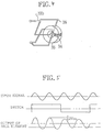
- Fig. 4 shows an arrangement of the core 35, the Hall-effect element 34, and the primary conductor 36 in detail.
- the Hall element 34 is arranged within a gap defined by the core 35.
- the primary conductor 36 is wound around the core 35 to provide a single turn and a reverse single turn which are selectively activated by the switch 32b one at a time. In other words, the primary conductor 36 effectively passes through the core 35 only once.
- the switch 32b is for selectively switching a winding direction of the primary conductor 36 with respect to the core 35, namely, a direction of the current flowing through the primary conductor 36.
- the switch 32a is connected to an output terminal of the auxiliary voltage transformer 11 so as to reverse a direction of the current flowing from the auxiliary voltage transformer 11 to the Hall element 34. Accordingly, by on-off control of the switches 32a and 32b, it is readily possible to change the direction of the current i supplied from the auxiliary voltage transformer 11 through the switch 32a to the Hall element 34 and the direction of the magnetic field B applied from the primary conductor 36 through the switch 32b to the Hall element 34.
- the offset voltage Vou is removed as follows.
- the switches 32a and 32b are controlled so that the directions of both the current i and the magnetic field B are positive during a particular cycle and negative during a next following cycle.
- the total output voltage produced by the Hall element 34 during these two cycles is integrated.
- a reference numeral 38 represents a control circuit for controlling the switches 32 and 32b.
- an input signal is depicted in a first or an uppermost row.
- the input signal is representative of the current supplied through the auxiliary voltage transformer 11 and the magnetic field supplied through the primary conductor 36.
- the switches 32a and 32b are switched in every two cycles of the input signal as depicted in a second row in the figure. Every time when the switches 32a and 32b are switched, the difference 2Vou between +Vou and -Vou is produced in the output voltage of the Hall element 34, as shown in a third or a lowermost row in the figure.
- the offset voltage is compensated by integrating the output voltage in the successive two cycles before and after switching of the switches 32a, 32b.
- the Hall element is used as the magneto-electric conversion element.
- a magnetic reluctance element or a superconductor conversion element may be used as the magneto-electric conversion element.
Landscapes
- Engineering & Computer Science (AREA)
- Power Engineering (AREA)
- Physics & Mathematics (AREA)
- General Physics & Mathematics (AREA)
- Measuring Magnetic Variables (AREA)
- Measurement Of Current Or Voltage (AREA)
Claims (4)
- Elektronischer Elektrizitätszähler, enthaltend:gekennzeichnet durcha) ein magneto-elektrisches Umsetzelement (34), dem ein Strom zugeführt wird, proportional zu einer Lastspannung, und an dem ein Magnetwert proportional zu einem Laststrom anliegt, zum Erzeugen einer Ausgangsspannung proportional zu einer Lastleistung, die durch die Lastspannung und den Laststrom vorgegeben ist,b) eine erste Schaltvorrichtung (32a) zum periodischen Umkehren - gemäß einem vorgegebenen Zyklus - der Richtung des Stroms proportional zu der Lastspannung, der dem magneto-elektrischen Umsetzelement (34) zugeführt wird, undc) eine Integriereinrichtung (37) zum Integrieren der Ausgangsspannung des magneto-elektrischen Umsetzelements (34),
d) eine zweite Schaltvorrichtung (32b) in Wechselwirkung zu der ersten Schaltvorrichtung (32a) zum periodischen Umkehren der Richtung des Magnetfelds proportional zu dem Laststrom, das an dem magneto-elektrischen Umsetzelement anliegt. - Elektronischer Elektrizitätszähler nach Anspruch 1, dadurch gekennzeichnet, dass es ferner enthält:a) einen Hilfsspannungstransformator (11) zum Speisen des magneto-elektrischen Umsetzelements zum Erzeugen eines Spannungsausgangssignals proportional zu der Lastspannung einer Verteilungsleitung,b) einen Hilfsstromtransformator (12) zum Speisen des magneto-elektrischen Umsetzelements (34) zum Erzeugen eines Stromausgangssignals proportional zu dem Verbrauchsstrom, wodurch das Stromausgangssignal in das Magnetfeld umgesetzt wird, undc) eine Spannungs/Frequenz-Umsetzschaltung (14), gespeist durch die Integriervorrichtung (37) mit der Ausgangsspannung proportional zu der Lastleistung zum Integrieren der Ausgangsspannung, zum Erzeugen eines Pulssignals.
- Elektronischer Elektrizitätszähler nach Anspruch 2, dadurch gekennzeichnet, dass es ferner enthält:a) eine Frequenzteilerschaltung (15) zum Gewichten des Pulssignals von der Spannungs/Frequenz-Umsetzschaltung (14) zum Erzeugen eines geteilten Pulssignals proportional zu der Lastleitung, undb) eine Anzeigeschaltung (16), die auf das geteilte Pulssignal von der Frequenz/Teiler-Schaltung (15) anspricht, zum Anzeigen der Menge des elektrischen Energieverbrauchs.
- Elektronischer Elektrizitätszähler nach einem der Ansprüche 1 bis 3, dadurch gekennzeichnet, dass das magneto-elektrische Umsetzelement (34) ein Hall-Element enthält.
Applications Claiming Priority (4)
| Application Number | Priority Date | Filing Date | Title |
|---|---|---|---|
| JP305787/91 | 1991-11-21 | ||
| JP3305787A JP3002310B2 (ja) | 1991-11-21 | 1991-11-21 | 電力量計 |
| JP30578791 | 1991-11-21 | ||
| EP92119709A EP0543365B1 (de) | 1991-11-21 | 1992-11-19 | Elektronischer Wattstundenzähler |
Related Parent Applications (2)
| Application Number | Title | Priority Date | Filing Date |
|---|---|---|---|
| EP92119709.1 Division | 1992-11-19 | ||
| EP92119709A Division EP0543365B1 (de) | 1991-11-21 | 1992-11-19 | Elektronischer Wattstundenzähler |
Publications (3)
| Publication Number | Publication Date |
|---|---|
| EP0738895A2 EP0738895A2 (de) | 1996-10-23 |
| EP0738895A3 EP0738895A3 (de) | 1997-06-11 |
| EP0738895B1 true EP0738895B1 (de) | 2000-07-12 |
Family
ID=17949350
Family Applications (2)
| Application Number | Title | Priority Date | Filing Date |
|---|---|---|---|
| EP96111317A Expired - Lifetime EP0738895B1 (de) | 1991-11-21 | 1992-11-19 | Elektronischer Wattstundenzähler |
| EP92119709A Expired - Lifetime EP0543365B1 (de) | 1991-11-21 | 1992-11-19 | Elektronischer Wattstundenzähler |
Family Applications After (1)
| Application Number | Title | Priority Date | Filing Date |
|---|---|---|---|
| EP92119709A Expired - Lifetime EP0543365B1 (de) | 1991-11-21 | 1992-11-19 | Elektronischer Wattstundenzähler |
Country Status (5)
| Country | Link |
|---|---|
| US (2) | US5414349A (de) |
| EP (2) | EP0738895B1 (de) |
| JP (1) | JP3002310B2 (de) |
| KR (1) | KR960013751B1 (de) |
| DE (2) | DE69221436T2 (de) |
Families Citing this family (10)
| Publication number | Priority date | Publication date | Assignee | Title |
|---|---|---|---|---|
| JP3142994B2 (ja) * | 1993-07-21 | 2001-03-07 | 株式会社東芝 | 電力演算装置 |
| US6429639B1 (en) * | 1997-01-21 | 2002-08-06 | International Rectifier Corporation | Combined filter inductor and hall current sensor |
| US6392400B1 (en) * | 1998-10-08 | 2002-05-21 | Schlumberger Resource Management Services | High linearity, low offset interface for Hall effect devices |
| US6483291B1 (en) * | 2000-05-26 | 2002-11-19 | Chander P. Bhateja | Apparatus for measuring electrical power consumption |
| FR2854211B1 (fr) * | 2003-04-24 | 2005-07-01 | Black & Decker Inc | Cheville d'ancrage pour vis, et ensemble constitue d'une telle cheville d'ancrage et d'une vis |
| FR2860592B1 (fr) * | 2003-10-06 | 2006-01-21 | Michel Remy Jean Combier | Dispositif de mesure de courant sans contact, a grande dynamique, robuste et a bas cout. |
| TW200812575A (en) * | 2006-04-28 | 2008-03-16 | Alcon Inc | Formulations containing amide derivatives of carboxylic acid NSAIDs for topical administration to the eye |
| KR100877450B1 (ko) * | 2007-10-10 | 2009-01-07 | 김장수 | 관통구 개폐구조를 갖는 폐회로 전류변성기 |
| JP5793682B2 (ja) * | 2011-01-21 | 2015-10-14 | パナソニックIpマネジメント株式会社 | 電力計測装置 |
| US8907670B2 (en) * | 2011-09-26 | 2014-12-09 | Samsung Electro-Mechanics Co., Ltd. | Metering device and metering method |
Family Cites Families (15)
| Publication number | Priority date | Publication date | Assignee | Title |
|---|---|---|---|---|
| US4292582A (en) * | 1977-06-22 | 1981-09-29 | Nippon Klingage Kabushiki Kaisha | Residual voltage regulating circuit for hall element |
| JPS582084A (ja) * | 1981-06-26 | 1983-01-07 | Toshiba Corp | ホ−ル素子装置 |
| JPS58137774A (ja) * | 1982-02-10 | 1983-08-16 | Toshiba Corp | ホ−ル効果装置 |
| US4451633A (en) | 1982-08-19 | 1984-05-29 | Shell Oil Company | Olefin polymerization |
| FI67961C (fi) * | 1983-08-18 | 1985-06-10 | Valmet Oy | Pulsbredd-pulshoejd-multiplikator i en statisk kwh-maetare |
| US4555309A (en) | 1983-08-19 | 1985-11-26 | Phillips Petroleum Company | Control of a fractional distillation process |
| CH668146A5 (de) * | 1985-05-22 | 1988-11-30 | Landis & Gyr Ag | Einrichtung mit einem hallelement in integrierter halbleitertechnologie. |
| CH673160A5 (de) * | 1986-02-10 | 1990-02-15 | Landis & Gyr Ag | |
| YU46409B (sh) * | 1986-07-15 | 1993-10-20 | Iskra Kibernetika | Merilnik elektricne moci s hallovim senzorjem in z a/d pretvornikom |
| US4761605A (en) * | 1986-12-22 | 1988-08-02 | General Electric Company | Input switching in electronic watthour meter |
| CH677036A5 (de) * | 1987-08-06 | 1991-03-28 | Landis & Gyr Betriebs Ag | |
| YU238387A (en) * | 1987-12-24 | 1990-10-31 | Iskra | Gauge of electric power - energy with hall's sensor |
| YU55688A (en) * | 1988-03-18 | 1991-01-28 | Iskra | Circuit for supplying multiplier with hall's sensors |
| ES2040012T3 (es) * | 1989-12-14 | 1993-10-01 | Landis & Gyr Business Support Ag | Disposicion para la determinacion de valores de magnitudes electricas, que se pueden deducir de valores de medida de al menos dos magnitudes electricas de entrada de la disposicion. |
| DE9012839U1 (de) * | 1990-09-08 | 1991-08-08 | EMH Energie-Messtechnik GmbH, 2094 Brackel | Elektrizitätszähler |
-
1991
- 1991-11-21 JP JP3305787A patent/JP3002310B2/ja not_active Expired - Fee Related
-
1992
- 1992-11-19 DE DE69221436T patent/DE69221436T2/de not_active Expired - Fee Related
- 1992-11-19 EP EP96111317A patent/EP0738895B1/de not_active Expired - Lifetime
- 1992-11-19 DE DE69231257T patent/DE69231257T2/de not_active Expired - Fee Related
- 1992-11-19 EP EP92119709A patent/EP0543365B1/de not_active Expired - Lifetime
- 1992-11-20 US US07/979,214 patent/US5414349A/en not_active Expired - Lifetime
- 1992-11-21 KR KR1019920021956A patent/KR960013751B1/ko not_active Expired - Fee Related
-
1995
- 1995-01-06 US US08/369,398 patent/US5475303A/en not_active Expired - Lifetime
Also Published As
| Publication number | Publication date |
|---|---|
| KR960013751B1 (ko) | 1996-10-10 |
| DE69231257D1 (de) | 2000-08-17 |
| DE69231257T2 (de) | 2000-12-21 |
| DE69221436D1 (de) | 1997-09-11 |
| US5414349A (en) | 1995-05-09 |
| DE69221436T2 (de) | 1998-01-08 |
| US5475303A (en) | 1995-12-12 |
| EP0543365B1 (de) | 1997-08-06 |
| EP0738895A2 (de) | 1996-10-23 |
| EP0543365A1 (de) | 1993-05-26 |
| JPH05142272A (ja) | 1993-06-08 |
| EP0738895A3 (de) | 1997-06-11 |
| JP3002310B2 (ja) | 2000-01-24 |
Similar Documents
| Publication | Publication Date | Title |
|---|---|---|
| US5565765A (en) | Current sensor operating according to the compensation theorem | |
| US5568047A (en) | Current sensor and method using differentially generated feedback | |
| US6433981B1 (en) | Modular current sensor and power source | |
| EP0738895B1 (de) | Elektronischer Wattstundenzähler | |
| US5146156A (en) | Current intensity transformer device for measuring a variable electric current | |
| US5345169A (en) | Current measuring device | |
| US4278940A (en) | Means for automatically compensating DC magnetization in a transformer | |
| EP0929139A3 (de) | Elektronische Auslöseeinheit mit vorrangigem Stromsensor | |
| JPS6450718A (en) | Method and circuit for controlling operation of parallel electric source and electric systems | |
| US7031131B2 (en) | Overload current protection apparatus | |
| CA2071592A1 (en) | Magnetic head driving circuit | |
| EP0225006B1 (de) | Stromfühleranordnung und Methode für die Steuerschaltung eines Leistungsschalters | |
| JPS5772069A (en) | Dc current detector | |
| JPS55131823A (en) | Voltage-regulated power supply | |
| JP2611635B2 (ja) | 直流電流計測器 | |
| JP3038276B2 (ja) | 電子式電力量計 | |
| US4377758A (en) | Magnetic amplifying apparatus | |
| US5446352A (en) | Series or compound motor control circuit having dual series windings | |
| EP1108260B1 (de) | Strommundlerschaltung mit zweistufigem strom | |
| RU1817178C (ru) | Устройство дл защиты от токовой перегрузки | |
| SU773608A1 (ru) | Источник питани посто нного тока | |
| SU1064403A1 (ru) | Преобразователь посто нного напр жени в переменное | |
| JPS56164962A (en) | Current detecting circuit | |
| SU1001447A1 (ru) | Генератор пр моугольных колебаний | |
| RU1810837C (ru) | Устройство дл измерени падени напр жени на контактах |
Legal Events
| Date | Code | Title | Description |
|---|---|---|---|
| PUAI | Public reference made under article 153(3) epc to a published international application that has entered the european phase |
Free format text: ORIGINAL CODE: 0009012 |
|
| 17P | Request for examination filed |
Effective date: 19960712 |
|
| AC | Divisional application: reference to earlier application |
Ref document number: 543365 Country of ref document: EP |
|
| AK | Designated contracting states |
Kind code of ref document: A2 Designated state(s): CH DE FR GB LI |
|
| PUAL | Search report despatched |
Free format text: ORIGINAL CODE: 0009013 |
|
| AK | Designated contracting states |
Kind code of ref document: A3 Designated state(s): CH DE FR GB LI |
|
| 17Q | First examination report despatched |
Effective date: 19980824 |
|
| GRAG | Despatch of communication of intention to grant |
Free format text: ORIGINAL CODE: EPIDOS AGRA |
|
| GRAG | Despatch of communication of intention to grant |
Free format text: ORIGINAL CODE: EPIDOS AGRA |
|
| GRAH | Despatch of communication of intention to grant a patent |
Free format text: ORIGINAL CODE: EPIDOS IGRA |
|
| GRAH | Despatch of communication of intention to grant a patent |
Free format text: ORIGINAL CODE: EPIDOS IGRA |
|
| GRAA | (expected) grant |
Free format text: ORIGINAL CODE: 0009210 |
|
| AC | Divisional application: reference to earlier application |
Ref document number: 543365 Country of ref document: EP |
|
| AK | Designated contracting states |
Kind code of ref document: B1 Designated state(s): CH DE FR GB LI |
|
| REG | Reference to a national code |
Ref country code: CH Ref legal event code: NV Representative=s name: E. BLUM & CO. PATENTANWAELTE Ref country code: CH Ref legal event code: EP |
|
| REF | Corresponds to: |
Ref document number: 69231257 Country of ref document: DE Date of ref document: 20000817 |
|
| ET | Fr: translation filed | ||
| PLBE | No opposition filed within time limit |
Free format text: ORIGINAL CODE: 0009261 |
|
| STAA | Information on the status of an ep patent application or granted ep patent |
Free format text: STATUS: NO OPPOSITION FILED WITHIN TIME LIMIT |
|
| 26N | No opposition filed | ||
| REG | Reference to a national code |
Ref country code: GB Ref legal event code: IF02 |
|
| REG | Reference to a national code |
Ref country code: GB Ref legal event code: 746 Effective date: 20070318 |
|
| REG | Reference to a national code |
Ref country code: CH Ref legal event code: PFA Owner name: KABUSHIKI KAISHA TOSHIBA Free format text: KABUSHIKI KAISHA TOSHIBA#72, HORIKAWA-CHO, SAIWAI-KU#KAWASAKI-SHI, KANAGAWA-KEN 210-8572 (JP) -TRANSFER TO- KABUSHIKI KAISHA TOSHIBA#72, HORIKAWA-CHO, SAIWAI-KU#KAWASAKI-SHI, KANAGAWA-KEN 210-8572 (JP) |
|
| PGFP | Annual fee paid to national office [announced via postgrant information from national office to epo] |
Ref country code: DE Payment date: 20071115 Year of fee payment: 16 |
|
| PGFP | Annual fee paid to national office [announced via postgrant information from national office to epo] |
Ref country code: CH Payment date: 20071114 Year of fee payment: 16 |
|
| PGFP | Annual fee paid to national office [announced via postgrant information from national office to epo] |
Ref country code: GB Payment date: 20071114 Year of fee payment: 16 Ref country code: FR Payment date: 20071108 Year of fee payment: 16 |
|
| REG | Reference to a national code |
Ref country code: CH Ref legal event code: PL |
|
| GBPC | Gb: european patent ceased through non-payment of renewal fee |
Effective date: 20081119 |
|
| REG | Reference to a national code |
Ref country code: FR Ref legal event code: ST Effective date: 20090731 |
|
| PG25 | Lapsed in a contracting state [announced via postgrant information from national office to epo] |
Ref country code: LI Free format text: LAPSE BECAUSE OF NON-PAYMENT OF DUE FEES Effective date: 20081130 Ref country code: DE Free format text: LAPSE BECAUSE OF NON-PAYMENT OF DUE FEES Effective date: 20090603 Ref country code: CH Free format text: LAPSE BECAUSE OF NON-PAYMENT OF DUE FEES Effective date: 20081130 |
|
| PG25 | Lapsed in a contracting state [announced via postgrant information from national office to epo] |
Ref country code: GB Free format text: LAPSE BECAUSE OF NON-PAYMENT OF DUE FEES Effective date: 20081119 |
|
| PG25 | Lapsed in a contracting state [announced via postgrant information from national office to epo] |
Ref country code: FR Free format text: LAPSE BECAUSE OF NON-PAYMENT OF DUE FEES Effective date: 20081130 |