EP0543341A2 - Einrichtung und Verfahren zum Zusammenstecken von optischen Steckverbindern - Google Patents
Einrichtung und Verfahren zum Zusammenstecken von optischen Steckverbindern Download PDFInfo
- Publication number
- EP0543341A2 EP0543341A2 EP92119632A EP92119632A EP0543341A2 EP 0543341 A2 EP0543341 A2 EP 0543341A2 EP 92119632 A EP92119632 A EP 92119632A EP 92119632 A EP92119632 A EP 92119632A EP 0543341 A2 EP0543341 A2 EP 0543341A2
- Authority
- EP
- European Patent Office
- Prior art keywords
- optical connector
- matching agent
- optical
- connection
- connectors
- Prior art date
- Legal status (The legal status is an assumption and is not a legal conclusion. Google has not performed a legal analysis and makes no representation as to the accuracy of the status listed.)
- Granted
Links
Images


Classifications
-
- G—PHYSICS
- G02—OPTICS
- G02B—OPTICAL ELEMENTS, SYSTEMS OR APPARATUS
- G02B6/00—Light guides; Structural details of arrangements comprising light guides and other optical elements, e.g. couplings
- G02B6/24—Coupling light guides
- G02B6/26—Optical coupling means
- G02B6/35—Optical coupling means having switching means
- G02B6/3564—Mechanical details of the actuation mechanism associated with the moving element or mounting mechanism details
- G02B6/3568—Mechanical details of the actuation mechanism associated with the moving element or mounting mechanism details characterised by the actuating force
-
- G—PHYSICS
- G02—OPTICS
- G02B—OPTICAL ELEMENTS, SYSTEMS OR APPARATUS
- G02B26/00—Optical devices or arrangements for the control of light using movable or deformable optical elements
- G02B26/02—Optical devices or arrangements for the control of light using movable or deformable optical elements for controlling the intensity of light
-
- G—PHYSICS
- G02—OPTICS
- G02B—OPTICAL ELEMENTS, SYSTEMS OR APPARATUS
- G02B6/00—Light guides; Structural details of arrangements comprising light guides and other optical elements, e.g. couplings
- G02B6/24—Coupling light guides
- G02B6/36—Mechanical coupling means
- G02B6/38—Mechanical coupling means having fibre to fibre mating means
- G02B6/3807—Dismountable connectors, i.e. comprising plugs
- G02B6/381—Dismountable connectors, i.e. comprising plugs of the ferrule type, e.g. fibre ends embedded in ferrules, connecting a pair of fibres
- G02B6/3818—Dismountable connectors, i.e. comprising plugs of the ferrule type, e.g. fibre ends embedded in ferrules, connecting a pair of fibres of a low-reflection-loss type
- G02B6/382—Dismountable connectors, i.e. comprising plugs of the ferrule type, e.g. fibre ends embedded in ferrules, connecting a pair of fibres of a low-reflection-loss type with index-matching medium between light guides
-
- G—PHYSICS
- G02—OPTICS
- G02B—OPTICAL ELEMENTS, SYSTEMS OR APPARATUS
- G02B6/00—Light guides; Structural details of arrangements comprising light guides and other optical elements, e.g. couplings
- G02B6/24—Coupling light guides
- G02B6/36—Mechanical coupling means
- G02B6/38—Mechanical coupling means having fibre to fibre mating means
- G02B6/3807—Dismountable connectors, i.e. comprising plugs
- G02B6/3873—Connectors using guide surfaces for aligning ferrule ends, e.g. tubes, sleeves, V-grooves, rods, pins, balls
- G02B6/3885—Multicore or multichannel optical connectors, i.e. one single ferrule containing more than one fibre, e.g. ribbon type
-
- G—PHYSICS
- G02—OPTICS
- G02B—OPTICAL ELEMENTS, SYSTEMS OR APPARATUS
- G02B6/00—Light guides; Structural details of arrangements comprising light guides and other optical elements, e.g. couplings
- G02B6/24—Coupling light guides
- G02B6/36—Mechanical coupling means
- G02B6/38—Mechanical coupling means having fibre to fibre mating means
- G02B6/3807—Dismountable connectors, i.e. comprising plugs
- G02B6/3897—Connectors fixed to housings, casing, frames or circuit boards
-
- G—PHYSICS
- G02—OPTICS
- G02B—OPTICAL ELEMENTS, SYSTEMS OR APPARATUS
- G02B6/00—Light guides; Structural details of arrangements comprising light guides and other optical elements, e.g. couplings
- G02B6/24—Coupling light guides
- G02B6/26—Optical coupling means
- G02B6/35—Optical coupling means having switching means
- G02B6/3502—Optical coupling means having switching means involving direct waveguide displacement, e.g. cantilever type waveguide displacement involving waveguide bending, or displacing an interposed waveguide between stationary waveguides
- G02B6/3508—Lateral or transverse displacement of the whole waveguides, e.g. by varying the distance between opposed waveguide ends, or by mutual lateral displacement of opposed waveguide ends
-
- G—PHYSICS
- G02—OPTICS
- G02B—OPTICAL ELEMENTS, SYSTEMS OR APPARATUS
- G02B6/00—Light guides; Structural details of arrangements comprising light guides and other optical elements, e.g. couplings
- G02B6/24—Coupling light guides
- G02B6/26—Optical coupling means
- G02B6/35—Optical coupling means having switching means
- G02B6/354—Switching arrangements, i.e. number of input/output ports and interconnection types
- G02B6/3554—3D constellations, i.e. with switching elements and switched beams located in a volume
- G02B6/3556—NxM switch, i.e. regular arrays of switches elements of matrix type constellation
Definitions
- the present invention relates to an optical connector connecting apparatus which is excellent in reproducibility of a connection loss to be measured, and is used for the connection of a multi-core optical connector having guide pins. Also, the invention relates to an optical connector connecting apparatus and an optical connector connecting method in which an optical path switching excellent in reproducibility is effected.
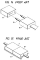
- a pair of optical connectors 61 and 62 are guided through guide pins 64 as shown in Fig. 14, and are connected together, and then as shown in Fig. 15, these connectors 61 and 62 thus connected are fixed together by a resilient clip 63.
- the fixing by the clip 63 must be done manually, so that much labor and time have been required, and another drawback is that the reproducibility of the measured value has been poor.
- connection apparatuses using a general-purposed robot or an X-Y-Z stage movable in three axes directions.
- the above-mentioned connecting apparatuses using the robot or the X-Y-Z stage are of such a construction that optical connectors are connected by guide pins or a ferrule, and therefore the positioning of the guide pins must be done with a high precision on the order of not more than a micron. Therefore, much labor and time have been required for the positioning, and besides the positioning control mechanism has become bulky, which has disadvantageously resulted in high costs.
- the connecting surfaces of the optical connectors have fine depressions and projections, and it is possible that when these connectors are connected together, a gap on the order of 0.1 ⁇ m to several tens of ⁇ m will be formed between optical fiber cores of the connectors. Therefore, in order to prevent a connection loss and a deterioration of reflection characteristics which are caused by this gap, it is a common practice to fill this gap with a matching agent which matches the refractive index with the optical fiber core.
- the matching agent is manually applied to connecting surfaces, using an applicator 65 as shown in Fig. 16 or a toothpick. However, much labor and time have been required for such a manual application of the matching agent.
- connection surfaces of a pair of opposed fixed and movable optical connectors to be connected together can be positively brought into intimate contact with each other using guide pins or a ferrule.
- connection surfaces are disposed perpendicular to the guide pins or the ferrule, there are two kinds of deviations of the guide pin or the ferrule from its mating fitting hole, that is, the deviation due to a parallel movement and the deviation due to the rotation or the bending.
- the present invention provides an optical connector connecting apparatus including a first optical connector fixedly supported on a body of the apparatus; a second optical connector movably supported on the apparatus body, the second optical connector being moved to be connected to the first optical connector; and an elastic member for mediating between one of the optical connectors and the apparatus body, wherein a connection loss or reflection produced by a connection of the optical connectors is measured.
- FIG. 1 to 4 A first embodiment of an optical connector connecting apparatus of the present invention is shown in Figs. 1 to 4, and this embodiment will now be described with reference to these Figures.
- Fig. 1 shows a basic construction of the first embodiment.
- a plurality of fixed optical connectors (first optical connectors) 1 are mounted on fixed members 3 in a lined-up manner.
- a movable optical connector (second optical connector) 2 is mounted on an optical connector containing member 4 in opposed relation to the fixed optical connectors 1.
- the optical connector containing member 4 is fixedly secured through a small-diameter beam (elastic member) 6 (1.5 mm in diameter in this embodiment) to a support member 7 on an apparatus body 10.
- a support bed 12 is supported on a base 11 through a ball thread 13 and guide shafts 14 so as to move in an X-axis direction, the base 11 constituting part of the apparatus body 10.
- An X-axis motor 15 mounted on the base 11 rotates the ball thread 13 to move the support bed 12 in the X-axis direction.
- a moving plate 22 is supported on the support bed 12 through a ball thread 23 and guide shafts 24 so as to move in a Y-axis direction perpendicular to the X-axis direction.
- a Y-axis motor 25 mounted on the support bed 12 rotates the ball thread 23 to move the moving plate 22 in the Y-axis direction.
- the above-mentioned support member 7 is supported on the moving plate 22 through a ball thread 33 and guide shafts 34 so as to move in a Z-axis direction perpendicular to the X-axis direction and the Y-axis direction.
- a Z-axis motor 35 mounted on the moving plate 22 rotates the ball thread 33 to move the support member 7 in the Z-axis direction.
- the apparatus is constituted by the support member 7, the base 11, the ball threads 13, 23 and 33, the guide shafts 14, 24 and 34, the motors 15, 25 and 35 and so on, and the apparatus body 10 serving as the X-Y-Z stage movably supports the movable optical connector 2 through the small-diameter beam 6.
- the motors 15, 25 and 35 on the apparatus body 10 are driven under a servo control to move the support member 7 to a prescribed address in the sequence of the X-axis, the Y-axis and the Z-axis.
- the movable optical connector 2 supported through the small-diameter beam 6 is positioned, and is connected to the fixed optical connector 1 to measure the amount of the optical attenuation.
- the movable optical connector 2 is mounted on the support member 7 through the small-diameter beam 6, and therefore when the above connection is to be effected, the connector 2 is sufficiently displaced with a small force, following the opposed fixed optical connector 1, so that the good connection can be achieved.
- the connection is to be released by returning the support member 7 toward the movable plate 22, the restraint by the fixed optical connector 1 is released, and the support member is returned to the neutral position by the elasticity of the small-diameter beam 6.
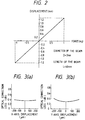
- the relation between the force and the displacement is generally linear as shown in Fig. 2, and there are provided the characteristics without normal and reverse hysteresis, and a displacement of 0.4 mm or more is produced with a force of 1 kg.
- Figs. 3(a) and 3(b) show the dependency of the connection loss on the displacement amount in this embodiment.
- Fig. 3(a) shows the relation between the connection loss and the displacement in the X-axis direction
- Fig. 3(b) shows the relation between the connection loss and the displacement in the Y-axis direction.
- Figs. 4(a) and 4(b) show a similar relation in connection with a comparative example, and show the relation between the displacement and the optical connection loss in the case where a movable optical connector is mounted within a box-like container with a gap.
- Figs. 3(a) and 3(b) show the dependency of the connection loss on the displacement amount in this embodiment.
- Fig. 3(a) shows the relation between the connection loss and the displacement in the X-axis direction
- Fig. 3(b) shows the relation between the connection loss and the displacement in the Y-axis direction.
- Figs. 4(a) and 4(b) show a similar relation
- connection loss greatly varies, and therefore the position dependency in the X-axis and Y-axis directions can not be read, and from the view point of the reproducibility the effect achieved by the construction of the embodiment of the present invention has become clear from these Figures.
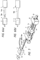
- FIGs. 5(a) and 5(b) An apparatus body used here is the same as that used in the first embodiment, and explanation thereof will be omitted.
- Fig. 5(a) two small-diameter beams 46a of a cylindrical shape are disposed parallel to each other, and are interposed between a support member 7 and an optical connector containing member 4, and a movable optical connector 2 is supported through the two small-diameter beams 46a.
- Fig. 5(b) four small-diameter beams 46b are disposed parallel to one another, and are interposed similarly. Therefore, the movable optical connector 2 properly corrects a position deviation through the flexing of the small-diameter beams 46a or 46b.
- FIGS. 6(a) and 6(b) show a third embodiment of the present invention, and this embodiment will now be described with reference to this Figure. Explanation of an apparatus body will be omitted as in the above embodiment.
- a movable optical connector 2 properly corrects a position deviation through the flexing of the small-diameter beam 56a or 56b of such a shape.
- FIG. 7 shows a fourth embodiment of the present invention, and this embodiment will now be described with reference to this Figure. Explanation of a lower portion of an apparatus body 10 will be omitted as in the foregoing.
- a support member 7 is supported on a moving plate 22 through a ball thread 33 and guide shafts 34 so as to move in a Z-axis direction, and the ball thread 33 is rotated by a Z-axis motor 35 mounted on the moving plate 22.
- a support block 9 is mounted on the support member 7 through a coil spring (spring member) 8, and an optical connector containing member 4 is mounted on the support block 9 through a small-diameter beam 6. Therefore, a spring force can be produced in the Z-axis direction which is the connection axis direction.
- a movable connector 2 is fixedly mounted on the optical connector containing member 4.
- the optical attenuation amount is measured using the movable optical connector as the measurement-side optical connector whereas the fixed optical connector is used as the light source-side connector, this may be reversed, that is, the movable optical connector may be the light source-side one whereas the fixed optical connector may be the measurement-side one.
- the optical connector is mounted on the apparatus body through the flexible member such as the elastic member, and as a result when the optical connectors are to be connected together, such opposed optical connectors are suitably brought into agreement with each other to be connected together. Therefore, the reproducibility of the connection loss amount is excellent, and besides the need for a fine positioning mechanism which would make the apparatus complicated is obviated. Therefore, the automatic measurement apparatus can be easily produced.
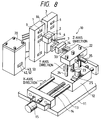
- FIG. 8 to 11 a fifth embodiment of an optical connector connecting apparatus of the present invention is shown in Figs. 8 to 11, and this embodiment will now be described with reference to these Figures.
- the optical connector connecting apparatus in this embodiment is the same in construction as that in the first embodiment shown in Fig. 1, except for the provision of a matching agent coating mechanism 20. Therefore, explanation of the same portions as those in the first embodiment will be omitted.
- the matching agent coating mechanism 20 is mounted on a base 11 in parallel relation to fixed members 3, and therefore the matching agent coating mechanism 20 faces the connecting surface of a movable optical connector 2.
- a pair of insertion holes 42 for respectively receiving guide pins 64 are formed in a lower portion of a case 40 which has at its upper portion a tank 41 for holding the matching agent.
- An outlet 43 is also formed in this lower portion, and is disposed between the insertion holes 42.
- the outlet 43 is connected to the tank 41 by an introduction passage 44, part of the introduction passage 44 intersects the insertion holes 42.
- a pair of plunger-like pins 45 are provided in registry respectively with the insertion holes 42.
- a spring 46 wound around the pin 45 normally urges a generally conically-shaped head of the pin 45 toward the outlet 43 to close the introduction passage 44. Therefore, the pins 45 and the springs 46 constitute the opening and closing means.
- the movable optical connector 2 approaches the case 40, and the guide pins 64 are inserted respectively into the insertion holes 42, so that the movable optical connector is abutted against the case 40. As a result, the pins 45 are retracted to open the introduction passage 44, and the matching agent is applied from the outlet 43 to be coated to the connecting surface 2a of the movable optical connector 2.
- the apparatus body 10 is driven under a servo control of the motors 15, 25 and 35 to move the support member 7 in the sequence of the X-axis, the Y-axis and the Z-axis.
- the movable optical connector 2 supported through the small-diameter beam 6 is positioned, and is connected to the fixed optical connector 1, thereby switching the optical path.
- the movable optical connector 2 instructed to be connected to a selected one of the fixed optical connectors 1, is first abutted against the matching agent coating mechanism 20 disposed in opposed relation to the movable optical connector 2, and the matching agent is coated to the end face of the movable optical connector 2.
- the movable optical connector 2 is abutted against the matching agent coating mechanism 20 either each time the instruction to connect the movable optical connector 2 to the fixed optical connector 1 is produced, or each time per they are connected a predetermined number (N) of times.
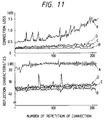
- Fig. 10 shows one example of operation program with respect to an optical connector connecting method of the present invention, and the operation will be described with reference to this Figure.
- Step S1 a required number of connections is recalled from the memory whenever the power switch is turned on.
- Step S3 the X-, Y- and Z-direction addresses of the fixed optical connector 1 to be connected are called, and the target position is confirmed.
- Step S4 the present connection number is judged, and if the connection number is not 0 or an integral multiple of N, the program shifts to Step S6. If the connection number is 0 or an integral multiple of N, the program shifts to Step S5.
- Step S5 a matching agent coating instruction is produced, and the movable optical connector 2 is moved in the sequence of the X-axis, the Y-axis and the Z-axis, and the guide pins 64 are inserted into the insertion holes 42 in the matching agent coating mechanism 20, so that the matching agent is coated onto the connecting surface 2a of the movable optical connector 2. Then, the movable optical connector 2 is withdrawn, and is returned to the initial position.
- Step S6 an instruction for the connection to the fixed optical connector 1 is produced, the movable optical connector 2 is moved in the sequence of the X-axis, the Y-axis and the Z-axis relative to the fixed optical connector to be connected, and is connected thereto. Then, in this condition, signals are sent to effect various measurements.
- a parallel motion of X and Y can be employed for the purpose of time-saving. In the latter case, Z motion should be independent to avoid the damage of guide pins and the connectors.
- Step S7 the count of a connection number counter is incremented one, and in Step S8, it is judged whether or not this connection number reaches the predetermined number. If this result is "NO”, the program returns to Step S1, and if this result is "YES", the program is finished.
- the case where the matching agent is not applied at all is a condition A.
- the case where the matching agent is applied each time the connection is effected is a condition B.
- the case where the matching agent is applied each time the connection is effected 10 times is a condition C.
- the case where the matching agent is applied each time the connection is effected 50 times is a condition D.
- the connection loss of the optical connector, as well as reflection characteristics thereof, was measured. As a result, as shown in Fig. 11, it has been confirmed that the characteristics in the conditions B and C are excellent.
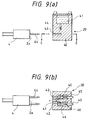
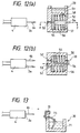
- FIG. 8 a sixth embodiment of an optical connector connecting apparatus of the present invention is shown in Figs. 8, 10, 11, 12(a) and 12(b), and this embodiment will now be described with reference to these Figures.
- Those portions identical to those of the fifth embodiment will be designated by identical reference numerals, respectively, and a repetition of the explanation is omitted.
- a cylinder 57 having a piston 55 urged left by a spring 56, is formed in a lower portion of a case 50 of a matching agent coating mechanism 20 which has at its upper portion a tank 51 for holding a matching agent.
- the tank 51 is communicated via a valve 58 with the space in the cylinder 57, and the valve 58 is opened and closed by the reciprocal movement of the piston 55 in right and left directions.
- an introduction passage 54 extending from the space of the cylinder 57 to an opening 53 disposed midway between insertion holes 52, and the matching agent is forced from the space of the cylinder 57 into the introduction passage 54 by the reciprocal movement of the piston 55, so that the matching agent is discharged from the opening 53.
- the movable optical connector 2 approaches the case 50, and the guide pins 64 are inserted respectively into the insertion holes 52, so that the movable optical connector 2 is abutted against the case 50.
- the piston 55 is moved right, so that the matching agent flows out of the case 50 to deposit on the connecting surface 2a of the movable optical connector 2.
- the spring 56 is urged left, and therefore the piston 55 is moved, and at the same time the valve 58 is opened to replenish the cylinder 57 with the matching agent.
- FIG. 8 a seventh embodiment of an optical connector connecting apparatus of the present invention is shown in Figs. 8, 10, 11 and 13, and this embodiment will now be described with reference to these Figures. Those portions identical to those of the fifth embodiment will be designated by identical reference numerals, respectively, and a repetition of the explanation is omitted.
- a swelling cloth 73 is supported on an outer peripheral surface of a tank 71 of a matching agent coating mechanism 20 which holds a matching agent.
- the lower end portion of the swelling cloth 73 is dipped in the matching agent.
- a pair of insertion holes 72 for respectively receiving the guide pins 64 are formed in the upper portion of the tank 71 in such a manner that the swelling cloth 73 is disposed between these insertion holes 72. Therefore, when the movable optical connector 2 is abutted against the swelling cloth 73 with the guide pins 64 inserted in the insertion holes 72, the matching agent impregnated in the swelling cloth 73 by a surface tension is applied to the connecting surface of the movable optical connector 2.
- the guide pins 64 of the movable optical connector 2 push the plunger-like pins 45 or the piston 55
- the part for pushing these pins 45 and piston 55 are not limited to the guide pins 64, and any part connected to the movable optical connector 2 may be used for this purpose.
- the matching agent is provided between the connecting surfaces when the optical connectors are connected together, and therefore the connection loss amount is reduced, and the fine positioning mechanism which makes the apparatus construction complicated becomes unnecessary.
Priority Applications (1)
| Application Number | Priority Date | Filing Date | Title |
|---|---|---|---|
| EP95104862A EP0677763B1 (de) | 1991-11-18 | 1992-11-17 | Einrichtung zum Zusammenstecken von optischen Steckverbindern mit Applikator für Flüssigkeit zur Indexanpassung |
Applications Claiming Priority (6)
| Application Number | Priority Date | Filing Date | Title |
|---|---|---|---|
| JP301710/91 | 1991-11-18 | ||
| JP30171091 | 1991-11-18 | ||
| JP30171091A JP3131256B2 (ja) | 1991-11-18 | 1991-11-18 | 光コネクタ測定用結合装置 |
| JP30514/92 | 1992-02-18 | ||
| JP3051492A JP3274485B2 (ja) | 1992-02-18 | 1992-02-18 | 光コネクタ結合装置 |
| JP3051492 | 1992-02-18 |
Related Child Applications (2)
| Application Number | Title | Priority Date | Filing Date |
|---|---|---|---|
| EP95104862.8 Division-Into | 1992-11-17 | ||
| EP95104862A Division EP0677763B1 (de) | 1991-11-18 | 1992-11-17 | Einrichtung zum Zusammenstecken von optischen Steckverbindern mit Applikator für Flüssigkeit zur Indexanpassung |
Publications (3)
| Publication Number | Publication Date |
|---|---|
| EP0543341A2 true EP0543341A2 (de) | 1993-05-26 |
| EP0543341A3 EP0543341A3 (en) | 1993-09-08 |
| EP0543341B1 EP0543341B1 (de) | 2001-09-26 |
Family
ID=26368897
Family Applications (2)
| Application Number | Title | Priority Date | Filing Date |
|---|---|---|---|
| EP92119632A Expired - Lifetime EP0543341B1 (de) | 1991-11-18 | 1992-11-17 | Einrichtung zum Zusammenstecken von optischen Steckverbindern |
| EP95104862A Expired - Lifetime EP0677763B1 (de) | 1991-11-18 | 1992-11-17 | Einrichtung zum Zusammenstecken von optischen Steckverbindern mit Applikator für Flüssigkeit zur Indexanpassung |
Family Applications After (1)
| Application Number | Title | Priority Date | Filing Date |
|---|---|---|---|
| EP95104862A Expired - Lifetime EP0677763B1 (de) | 1991-11-18 | 1992-11-17 | Einrichtung zum Zusammenstecken von optischen Steckverbindern mit Applikator für Flüssigkeit zur Indexanpassung |
Country Status (7)
| Country | Link |
|---|---|
| US (2) | US5418872A (de) |
| EP (2) | EP0543341B1 (de) |
| KR (1) | KR970004472B1 (de) |
| AU (1) | AU652299B2 (de) |
| CA (1) | CA2083193C (de) |
| DE (2) | DE69232082T2 (de) |
| TW (1) | TW229277B (de) |
Cited By (1)
| Publication number | Priority date | Publication date | Assignee | Title |
|---|---|---|---|---|
| WO2003009034A2 (en) * | 2001-07-17 | 2003-01-30 | 3M Innovative Properties Company | Protective packaging for optical fibres |
Families Citing this family (27)
| Publication number | Priority date | Publication date | Assignee | Title |
|---|---|---|---|---|
| EP0844506B1 (de) * | 1996-11-21 | 2003-08-13 | Sumitomo Electric Industries, Ltd. | Optischer Schalter und Schaltverfahren |
| US5937123A (en) * | 1998-04-22 | 1999-08-10 | Eastman Kodak Company | Fiber optical laser collimating device |
| US6236787B1 (en) | 1998-07-08 | 2001-05-22 | Optical Switch Corporation | Method and apparatus for aligning optical fibers using an alignment spacer |
| US6137930A (en) * | 1998-07-08 | 2000-10-24 | Optical Switch Corporation | Method and apparatus for aligning optical fibers |
| US6253007B1 (en) | 1998-07-08 | 2001-06-26 | Optical Switch Corporation | Method and apparatus for connecting optical fibers |
| US6236778B1 (en) | 1998-12-16 | 2001-05-22 | Optical Switch Corporation | Frustrated total internal reflection bus and method of operation |
| US6243511B1 (en) | 1999-02-04 | 2001-06-05 | Optical Switch Corporation | System and method for determining the condition of an optical signal |
| US6454469B1 (en) | 1999-06-29 | 2002-09-24 | International Business Machines Corporation | Actively aligned optical coupling assembly |
| US6453084B1 (en) | 2000-01-17 | 2002-09-17 | Optical Switch Corporation | System and method for beam-steering using a reference signal feedback |
| US6778729B1 (en) | 2000-04-17 | 2004-08-17 | The Boeing Company | Device and method for optical signal switching |
| US8527046B2 (en) | 2000-04-20 | 2013-09-03 | Medtronic, Inc. | MRI-compatible implantable device |
| US6925328B2 (en) | 2000-04-20 | 2005-08-02 | Biophan Technologies, Inc. | MRI-compatible implantable device |
| US6424758B1 (en) * | 2000-09-21 | 2002-07-23 | Yu-Feng Cheng | Optical fiber socket with an integral switch |
| US6829509B1 (en) | 2001-02-20 | 2004-12-07 | Biophan Technologies, Inc. | Electromagnetic interference immune tissue invasive system |
| US20020116028A1 (en) | 2001-02-20 | 2002-08-22 | Wilson Greatbatch | MRI-compatible pacemaker with pulse carrying photonic catheter providing VOO functionality |
| US6731979B2 (en) | 2001-08-30 | 2004-05-04 | Biophan Technologies Inc. | Pulse width cardiac pacing apparatus |
| US7054686B2 (en) | 2001-08-30 | 2006-05-30 | Biophan Technologies, Inc. | Pulsewidth electrical stimulation |
| WO2003037399A2 (en) | 2001-10-31 | 2003-05-08 | Biophan Technologies, Inc. | Hermetic component housing for photonic catheter |
| US6968236B2 (en) | 2002-01-28 | 2005-11-22 | Biophan Technologies, Inc. | Ceramic cardiac electrodes |
| US6711440B2 (en) | 2002-04-11 | 2004-03-23 | Biophan Technologies, Inc. | MRI-compatible medical device with passive generation of optical sensing signals |
| US6725092B2 (en) | 2002-04-25 | 2004-04-20 | Biophan Technologies, Inc. | Electromagnetic radiation immune medical assist device adapter |
| US6925322B2 (en) | 2002-07-25 | 2005-08-02 | Biophan Technologies, Inc. | Optical MRI catheter system |
| US7813600B1 (en) * | 2007-11-25 | 2010-10-12 | Teliswitch Solutions, Ltd. | Mechanical optical switch |
| US9631482B2 (en) | 2013-10-24 | 2017-04-25 | Saudi Arabian Oil Company | Method and apparatus for down-hole alignment of optic fibers |
| US9417395B2 (en) | 2014-12-29 | 2016-08-16 | Verizon Patent And Licensing Inc. | Optical interface with traffic protection using multi-optical path photonic switch |
| CN105945841B (zh) * | 2016-06-28 | 2017-12-26 | 深圳睿晟自动化技术有限公司 | 三自由度中心摆动平台 |
| CN111443438B (zh) * | 2020-04-13 | 2021-03-16 | 中南大学 | 基于音圈电机驱动的透镜耦合设备 |
Citations (7)
| Publication number | Priority date | Publication date | Assignee | Title |
|---|---|---|---|---|
| FR2521735A1 (fr) * | 1982-02-12 | 1983-08-19 | Thomson Csf Mat Tel | Commutateur optique a commande mecanique et dispositif optoelectronique de selection de programme comportant un tel commutateur |
| EP0098205A1 (de) * | 1982-06-25 | 1984-01-11 | SOURIAU & Cie (S.A.) | Fiberoptische Verbindung für einen Schiebeträger in einem Regalschrank |
| JPS6353503A (ja) * | 1986-08-25 | 1988-03-07 | Fujitsu Ltd | 光フアイバの終端構造 |
| EP0274446A2 (de) * | 1987-01-09 | 1988-07-13 | The Furukawa Electric Co., Ltd. | Methode und Gerät zum Schalten von optischen Steckern |
| EP0286337A1 (de) * | 1987-04-02 | 1988-10-12 | BRITISH TELECOMMUNICATIONS public limited company | Strahlungsablenkungsvorrichtung |
| EP0323920A2 (de) * | 1988-01-07 | 1989-07-12 | The Furukawa Electric Co., Ltd. | Optisches Schaltersystem |
| DE8910422U1 (de) * | 1989-08-31 | 1989-10-19 | Siemens Ag, 1000 Berlin Und 8000 Muenchen, De |
Family Cites Families (11)
| Publication number | Priority date | Publication date | Assignee | Title |
|---|---|---|---|---|
| US4223978A (en) * | 1979-03-09 | 1980-09-23 | Bell Telephone Laboratories, Incorporated | Mechanical optical fiber switching device |
| US4239332A (en) * | 1979-04-13 | 1980-12-16 | Trw Inc. | Self-aligning fiber optic relay |
| US4303302A (en) * | 1979-10-30 | 1981-12-01 | Gte Laboratories Incorporated | Piezoelectric optical switch |
| DE3206919A1 (de) * | 1982-02-26 | 1983-09-15 | Philips Patentverwaltung Gmbh, 2000 Hamburg | Vorrichtung zum optischen trennen und verbinden von lichtleitern |
| SE454546B (sv) * | 1982-07-01 | 1988-05-09 | Ericsson Telefon Ab L M | Fiberoptiskt kopplingsorgan for att omkoppla en optisk signalveg utford med atminstone en fast anordnad fiberende och minst en rorligt anordnad fiberende |
| FR2556849B1 (fr) * | 1983-12-16 | 1986-03-28 | Cit Alcatel | Attenuateur optique variable pour couplage de fibres optiques |
| US4896935A (en) * | 1985-10-07 | 1990-01-30 | Lee Ho Shang | Fiber optic switch |
| JP2591745B2 (ja) * | 1987-04-30 | 1997-03-19 | 住友電気工業株式会社 | 光コネクタの切替え装置及び切替え方法 |
| JPH0194307A (ja) * | 1987-10-07 | 1989-04-13 | Fujikura Ltd | 光ファイバコネクタの接続切替方法およびその装置 |
| JPH0199016A (ja) * | 1987-10-13 | 1989-04-17 | Nippon Telegr & Teleph Corp <Ntt> | 光ファイバスイッチ |
| US5113787A (en) * | 1988-05-20 | 1992-05-19 | Raychem Corp. | Optical fiber termination coating dispenser |
-
1992
- 1992-11-17 DE DE69232082T patent/DE69232082T2/de not_active Expired - Fee Related
- 1992-11-17 EP EP92119632A patent/EP0543341B1/de not_active Expired - Lifetime
- 1992-11-17 TW TW081109191A patent/TW229277B/zh active
- 1992-11-17 AU AU28473/92A patent/AU652299B2/en not_active Ceased
- 1992-11-17 DE DE69230153T patent/DE69230153T2/de not_active Expired - Fee Related
- 1992-11-17 KR KR1019920021549A patent/KR970004472B1/ko not_active IP Right Cessation
- 1992-11-17 EP EP95104862A patent/EP0677763B1/de not_active Expired - Lifetime
- 1992-11-18 CA CA002083193A patent/CA2083193C/en not_active Expired - Fee Related
-
1994
- 1994-04-04 US US08/222,007 patent/US5418872A/en not_active Expired - Fee Related
- 1994-08-31 US US08/298,833 patent/US5590227A/en not_active Expired - Fee Related
Patent Citations (7)
| Publication number | Priority date | Publication date | Assignee | Title |
|---|---|---|---|---|
| FR2521735A1 (fr) * | 1982-02-12 | 1983-08-19 | Thomson Csf Mat Tel | Commutateur optique a commande mecanique et dispositif optoelectronique de selection de programme comportant un tel commutateur |
| EP0098205A1 (de) * | 1982-06-25 | 1984-01-11 | SOURIAU & Cie (S.A.) | Fiberoptische Verbindung für einen Schiebeträger in einem Regalschrank |
| JPS6353503A (ja) * | 1986-08-25 | 1988-03-07 | Fujitsu Ltd | 光フアイバの終端構造 |
| EP0274446A2 (de) * | 1987-01-09 | 1988-07-13 | The Furukawa Electric Co., Ltd. | Methode und Gerät zum Schalten von optischen Steckern |
| EP0286337A1 (de) * | 1987-04-02 | 1988-10-12 | BRITISH TELECOMMUNICATIONS public limited company | Strahlungsablenkungsvorrichtung |
| EP0323920A2 (de) * | 1988-01-07 | 1989-07-12 | The Furukawa Electric Co., Ltd. | Optisches Schaltersystem |
| DE8910422U1 (de) * | 1989-08-31 | 1989-10-19 | Siemens Ag, 1000 Berlin Und 8000 Muenchen, De |
Non-Patent Citations (3)
| Title |
|---|
| IEICE TRANSACTIONS vol. E70, no. 10, October 1987, TOKYO JP pages 890 - 892 TATEDA ET AL. * |
| IEICE TRANSACTIONS vol. E70, no. 7, July 1987, TOKYO JP pages 623 - 624 SATAKE ET AL. * |
| PATENT ABSTRACTS OF JAPAN vol. 12, no. 271 (P-736)1988 & JP-A-63 053 503 ( FUJITSU LTD ) * |
Cited By (2)
| Publication number | Priority date | Publication date | Assignee | Title |
|---|---|---|---|---|
| WO2003009034A2 (en) * | 2001-07-17 | 2003-01-30 | 3M Innovative Properties Company | Protective packaging for optical fibres |
| WO2003009034A3 (en) * | 2001-07-17 | 2004-02-19 | 3M Innovative Properties Co | Protective packaging for optical fibres |
Also Published As
| Publication number | Publication date |
|---|---|
| DE69232082D1 (de) | 2001-10-31 |
| KR970004472B1 (ko) | 1997-03-28 |
| AU2847392A (en) | 1993-05-20 |
| KR930010571A (ko) | 1993-06-22 |
| TW229277B (de) | 1994-09-01 |
| DE69232082T2 (de) | 2002-03-07 |
| EP0543341A3 (en) | 1993-09-08 |
| US5590227A (en) | 1996-12-31 |
| CA2083193C (en) | 1998-01-06 |
| AU652299B2 (en) | 1994-08-18 |
| DE69230153T2 (de) | 2000-03-09 |
| EP0677763A1 (de) | 1995-10-18 |
| US5418872A (en) | 1995-05-23 |
| EP0677763B1 (de) | 1999-10-13 |
| EP0543341B1 (de) | 2001-09-26 |
| CA2083193A1 (en) | 1993-05-19 |
| DE69230153D1 (de) | 1999-11-18 |
Similar Documents
| Publication | Publication Date | Title |
|---|---|---|
| US5590227A (en) | Optical connector apparatus | |
| US6671108B2 (en) | Optical apparatus including lens | |
| US4832438A (en) | Installation for the alignment of an optical waveguide for splicing purposes | |
| US4759599A (en) | Optical connector | |
| CN105607161A (zh) | Grin透镜阵列、装有透镜的连接器和装有透镜的连接器系统 | |
| US6088503A (en) | Optical fiber precision handling tool | |
| US5469522A (en) | Optical fiber splice interconnection and usage method | |
| CA2172646C (en) | Optical attenuation fiber assembly | |
| CA2022245A1 (en) | High-precision adjustable injection molding of single-mode fiber optic connectors | |
| US4946247A (en) | Fiber optic bypass switch | |
| US6360032B1 (en) | Two beam optical switch and attenuator and method of use | |
| JP3274485B2 (ja) | 光コネクタ結合装置 | |
| DE4307974C1 (de) | Vorrichtung zur hochgenauen Drehung rotationssymmetrischer Bauteile, insbesondere von Lichtwellenleitern | |
| EP0187418A2 (de) | Vorrichtung zum Positionieren eines optischen Wellenleiters | |
| JP3131256B2 (ja) | 光コネクタ測定用結合装置 | |
| US20020081088A1 (en) | Housing for packaging optical device, method for receiving optical device, and optical device | |
| JP2595630Y2 (ja) | 光学関連部材駆動装置 | |
| US20060077559A1 (en) | Optical actuator sleeve assembly | |
| EP1460464A1 (de) | Optischer Steckverbinder mit einem beschichteten Faserstück als Koppelglied | |
| KR100236224B1 (ko) | 광섬유 융착접속용 리본 홀더 | |
| JPH0436715A (ja) | 光ファイバ用顕微鏡 | |
| CA1213424A (en) | Mirror mechanism for fusion-splicing apparatus | |
| JP3973927B2 (ja) | 光ファイバ接続器 | |
| JPS63294511A (ja) | 光フアイバ用多心一括切替スイツチ | |
| JPH07234367A (ja) | 光ファイバ配線切替装置 |
Legal Events
| Date | Code | Title | Description |
|---|---|---|---|
| PUAI | Public reference made under article 153(3) epc to a published international application that has entered the european phase |
Free format text: ORIGINAL CODE: 0009012 |
|
| AK | Designated contracting states |
Kind code of ref document: A2 Designated state(s): DE FR GB |
|
| PUAL | Search report despatched |
Free format text: ORIGINAL CODE: 0009013 |
|
| AK | Designated contracting states |
Kind code of ref document: A3 Designated state(s): DE FR GB |
|
| 17P | Request for examination filed |
Effective date: 19931104 |
|
| 17Q | First examination report despatched |
Effective date: 19941125 |
|
| RTI1 | Title (correction) |
Free format text: OPTICAL CONNECTOR CONNECTING APPARATUS |
|
| GRAG | Despatch of communication of intention to grant |
Free format text: ORIGINAL CODE: EPIDOS AGRA |
|
| RTI1 | Title (correction) |
Free format text: OPTICAL CONNECTOR CONNECTING APPARATUS |
|
| GRAG | Despatch of communication of intention to grant |
Free format text: ORIGINAL CODE: EPIDOS AGRA |
|
| GRAH | Despatch of communication of intention to grant a patent |
Free format text: ORIGINAL CODE: EPIDOS IGRA |
|
| GRAH | Despatch of communication of intention to grant a patent |
Free format text: ORIGINAL CODE: EPIDOS IGRA |
|
| GRAA | (expected) grant |
Free format text: ORIGINAL CODE: 0009210 |
|
| AK | Designated contracting states |
Kind code of ref document: B1 Designated state(s): DE FR GB |
|
| XX | Miscellaneous (additional remarks) |
Free format text: TEILANMELDUNG 95104862.8 EINGEREICHT AM 17/11/92. |
|
| REF | Corresponds to: |
Ref document number: 69232082 Country of ref document: DE Date of ref document: 20011031 |
|
| REG | Reference to a national code |
Ref country code: GB Ref legal event code: IF02 |
|
| ET | Fr: translation filed | ||
| PLBE | No opposition filed within time limit |
Free format text: ORIGINAL CODE: 0009261 |
|
| STAA | Information on the status of an ep patent application or granted ep patent |
Free format text: STATUS: NO OPPOSITION FILED WITHIN TIME LIMIT |
|
| 26N | No opposition filed | ||
| PGFP | Annual fee paid to national office [announced via postgrant information from national office to epo] |
Ref country code: FR Payment date: 20021108 Year of fee payment: 11 |
|
| PGFP | Annual fee paid to national office [announced via postgrant information from national office to epo] |
Ref country code: GB Payment date: 20021113 Year of fee payment: 11 |
|
| PGFP | Annual fee paid to national office [announced via postgrant information from national office to epo] |
Ref country code: DE Payment date: 20021121 Year of fee payment: 11 |
|
| PG25 | Lapsed in a contracting state [announced via postgrant information from national office to epo] |
Ref country code: GB Free format text: LAPSE BECAUSE OF NON-PAYMENT OF DUE FEES Effective date: 20031117 |
|
| PG25 | Lapsed in a contracting state [announced via postgrant information from national office to epo] |
Ref country code: DE Free format text: LAPSE BECAUSE OF NON-PAYMENT OF DUE FEES Effective date: 20040602 |
|
| GBPC | Gb: european patent ceased through non-payment of renewal fee |
Effective date: 20031117 |
|
| PG25 | Lapsed in a contracting state [announced via postgrant information from national office to epo] |
Ref country code: FR Free format text: LAPSE BECAUSE OF NON-PAYMENT OF DUE FEES Effective date: 20040730 |
|
| REG | Reference to a national code |
Ref country code: FR Ref legal event code: ST |