EP0542386B1 - Verfahren und Einrichtung zum Dämpfen der Schwingungen eines Schienenfahrzeuges - Google Patents
Verfahren und Einrichtung zum Dämpfen der Schwingungen eines Schienenfahrzeuges Download PDFInfo
- Publication number
- EP0542386B1 EP0542386B1 EP92250327A EP92250327A EP0542386B1 EP 0542386 B1 EP0542386 B1 EP 0542386B1 EP 92250327 A EP92250327 A EP 92250327A EP 92250327 A EP92250327 A EP 92250327A EP 0542386 B1 EP0542386 B1 EP 0542386B1
- Authority
- EP
- European Patent Office
- Prior art keywords
- rail vehicle
- cylinder
- piston
- rail
- pressure
- Prior art date
- Legal status (The legal status is an assumption and is not a legal conclusion. Google has not performed a legal analysis and makes no representation as to the accuracy of the status listed.)
- Expired - Lifetime
Links
Images

Classifications
-
- B—PERFORMING OPERATIONS; TRANSPORTING
- B61—RAILWAYS
- B61F—RAIL VEHICLE SUSPENSIONS, e.g. UNDERFRAMES, BOGIES OR ARRANGEMENTS OF WHEEL AXLES; RAIL VEHICLES FOR USE ON TRACKS OF DIFFERENT WIDTH; PREVENTING DERAILING OF RAIL VEHICLES; WHEEL GUARDS, OBSTRUCTION REMOVERS OR THE LIKE FOR RAIL VEHICLES
- B61F5/00—Constructional details of bogies; Connections between bogies and vehicle underframes; Arrangements or devices for adjusting or allowing self-adjustment of wheel axles or bogies when rounding curves
- B61F5/02—Arrangements permitting limited transverse relative movements between vehicle underframe or bolster and bogie; Connections between underframes and bogies
- B61F5/22—Guiding of the vehicle underframes with respect to the bogies
- B61F5/24—Means for damping or minimising the canting, skewing, pitching, or plunging movements of the underframes
- B61F5/245—Means for damping or minimising the canting, skewing, pitching, or plunging movements of the underframes by active damping, i.e. with means to vary the damping characteristics in accordance with track or vehicle induced reactions, especially in high speed mode
Definitions
- Such a device is also known from FR-A-2 593 455.
- the known solution aims at the goal in the field of railways Connection occurring with ever higher vehicle speeds To counteract rolling movements.
- a contemplated stake previous damper which are designed so that they the would dampen the vibration range of the roll movement, according to the expressed an excessive increase in the hardness of the Lead vehicle suspension. This would have a negative impact on the Shock and Vibration movements of the vehicle exercised.
- the invention specified in claim 1 is based on the problem the spring stiffness of a wheel / rail system at low frequencies to increase the damping system and at high frequencies To reduce spring stiffness, i.e. the cheapest damping adjust. At the same time, the system of passive Leave lateral force control and through a system of active Shear force control to be replaced.
- Another measure is that the pressure in the cylinder is on a setpoint calculated on the basis of a path signal is regulated and that when vibrations occur over the cylinder or over the piston Energy is fed back into a store. This can significantly increase Energy is saved and the print media source does not need more become.
- a program-controlled device a decision is made as to which of the valves formed circuit branch, the regulation of the actual pressure takes place. This can advantageously result in an energy and flow technology favorable pressure medium presence in the cylinder can be achieved.
- Another improvement is that the program-controlled Established an increase or decrease in the pressure level to influence the passive spring stiffness.
- the device for damping vibrations between one Rail vehicle body and a rail chassis is based on one acting between the rail vehicle body and the rail chassis Piston-cylinder drive unit that can be acted on from both sides.
- Such a device consists of a pneumatic or hydraulic piston-cylinder system with connected control device a displacement measuring device assigned to the piston and a System of control and non-return valves associated with pressure rooms.
- a such a device per vehicle is not of great weight connected or a large space for accommodation is required.
- the facility is further developed so that the system of Control and check valves in each pressure chamber in the cylinder allocated memory is connected. So both sides of the piston connectable to a memory.
- brackets 5 and 6 stabilizers 7 and 8 articulated, which consist of hydraulic dampers.
- These mechanical, hydraulic or pneumatic spring assemblies consisting of the coil springs 3 and 4, the stabilizers 7 and 8, catch in the transverse direction to the direction of travel 9 only partially arising vibrations.
- These vibrations also lie different passive forces with different dynamics.
- the Passive forces are vibrations generated by the rail vehicle itself, that cause the vehicle with its wheels or Wheel groups 10 and 11 back and forth between the rails of a track heart pendulums.
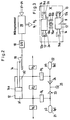
- each rail chassis 2 In order to match active forces to the passive forces that occur, is between the rail vehicle body 1 and a rail chassis 2 each have at least one pneumatic or hydraulic cylinder 12 arranged and with its end 12a on a hinge 13 on the Rail chassis 2 attached via a bearing 2a. His piston rod 14 is accordingly with a joint 14a on the Rail vehicle body 1 attached or stored. On the Rail chassis 2 are also supports 15a and 15b elastic stops 16a and 16b for one between the two arranged guide rod 17, which on the rail vehicle body 1 is attached.
- the piston 14a is double-sided in the cylinder 12 actable, the pressures p1 and p2 depending on Driving conditions are regulated by lower driving stiffness according to the dynamics and the level of active forces between Rail vehicle body and rail chassis are set.
- a length measuring device 18 with a path converter 19 provided, the signals input into a microprocessor 20 in which the signals of pressures p1 and p2 as well as others Press p3 and p4 of a first pressure accumulator 21 and a second one, respectively Pressure accumulator 22 can be entered.
- the microprocessor 20 outputs the calculated values in the form of signals to control or continuous valves V1, V2, V3 and V4 or V5 further, which are connected as shown.
- the pressure accumulators 21 and 22 are here via check valves 23 and 24 and this connected to a pressure source 25.
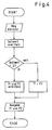
- the mode of operation of the device results from the flow master plan according to FIG. 4:
- a path "s" from the length measuring device 18 and the path converter 19 is read into the microprocessor 20 from the pressures p1 and p2.
- the setpoint is calculated, which is made available as a signal ramp. Accordingly, it is determined whether the target value is zero or greater than zero (cf. flow chart according to FIG. 4).
- the pressures p1 and p2 are then calculated from the setpoints and actual values as paths in the corresponding pressure spaces and as signals to the valves V1 to V5 in a system with the pressure accumulators 21 and 22.
- FIG. 3 a doubled arrangement is swapped with sides for Attachment of two cylinders 12 shown.
- cylinder 12 In the drawing above lying cylinder 12 is the piston rod 14 and the joint 14a on the right, however in the case of the lower cylinder 12 on the left side.
- the cylinder end 12a and the top cylinder 12 are located there Joint 13 on the left, however, in the lower cylinder 12 on the right side.
- the invention can both with a piston-cylinder system or with several according to FIG. 3 and also with more than two Piston-cylinder systems depending on the masses to be damped be realized.
Landscapes
- Engineering & Computer Science (AREA)
- Mechanical Engineering (AREA)
- Vehicle Body Suspensions (AREA)
- Fluid-Damping Devices (AREA)
- Vibration Prevention Devices (AREA)
Applications Claiming Priority (2)
| Application Number | Priority Date | Filing Date | Title |
|---|---|---|---|
| DE4137869A DE4137869C1 (enExample) | 1991-11-11 | 1991-11-11 | |
| DE4137869 | 1991-11-11 |
Publications (2)
| Publication Number | Publication Date |
|---|---|
| EP0542386A1 EP0542386A1 (de) | 1993-05-19 |
| EP0542386B1 true EP0542386B1 (de) | 1999-01-13 |
Family
ID=6445032
Family Applications (1)
| Application Number | Title | Priority Date | Filing Date |
|---|---|---|---|
| EP92250327A Expired - Lifetime EP0542386B1 (de) | 1991-11-11 | 1992-11-09 | Verfahren und Einrichtung zum Dämpfen der Schwingungen eines Schienenfahrzeuges |
Country Status (3)
| Country | Link |
|---|---|
| EP (1) | EP0542386B1 (enExample) |
| AT (1) | ATE175635T1 (enExample) |
| DE (1) | DE4137869C1 (enExample) |
Families Citing this family (6)
| Publication number | Priority date | Publication date | Assignee | Title |
|---|---|---|---|---|
| DE4420367C1 (de) * | 1994-06-10 | 1995-08-17 | Talbot Waggonfab | Querfederung für ein Schienenfahrzeug und Verfahren zu deren Steuerung |
| DE4436137A1 (de) * | 1994-10-10 | 1996-04-11 | Talbot Waggonfab | Verfahren zum Steuern der Querverschiebung eines Schienenfahrzeugs gegenüber seinem Fahrwerk |
| DE19501136C2 (de) * | 1995-01-05 | 2001-08-02 | Knorr Bremse Mrp Systeme Fuer | Verfahren und Einrichtung zur Dämpfung von Fahrschwingungen bei Fahrzeugen |
| DE19512437A1 (de) * | 1995-04-03 | 1996-10-10 | Rexroth Mannesmann Gmbh | Einrichtung zur Kompensation der auf ein Schienenfahrzeug wirkenden Querkraft |
| DE19606364C2 (de) * | 1995-05-06 | 1998-01-29 | Deutsche Bahn Ag | Modale Abstützung der Fahrwerke und/oder Transportgefäße von Verkehrsfahrzeugen,vorzugsweise Schienenfahrzeugen |
| DE19806347C1 (de) * | 1998-02-12 | 1999-07-15 | Mannesmann Ag | Vorrichtung zur aktiven Querzentrierung und Schwingungsdämpfung bei Schienenfahrzeugen (AQZ-Zylinder) |
Family Cites Families (9)
| Publication number | Priority date | Publication date | Assignee | Title |
|---|---|---|---|---|
| IT7470428A1 (it) * | 1974-11-25 | 1976-05-25 | Fabbriche Riunite Way Assauto S P A | Ammortizzatore antirollio per veicoli |
| JPS61275053A (ja) * | 1985-05-31 | 1986-12-05 | 財団法人鉄道総合技術研究所 | 車両の振動制御装置 |
| DE3537325A1 (de) * | 1985-10-19 | 1987-04-23 | Messerschmitt Boelkow Blohm | Aktives federungselement, insbesondere fuer schienengebundene hochgeschwindigkeitsfahrzeuge |
| JPH06104450B2 (ja) * | 1986-01-29 | 1994-12-21 | 財団法人鉄道総合技術研究所 | 車両の振動制御装置 |
| IT1216147B (it) * | 1988-03-18 | 1990-02-22 | Socimi | Dispositivo per il controllo delle sollecitazioni dinamiche trasmesse dalla superficie di rotolamento alla cassa di un veicolo, in particolare un veicolo ferrotramviario. |
| DE3818179A1 (de) * | 1988-05-28 | 1989-12-07 | Messerschmitt Boelkow Blohm | Aufhaengung fuer fahrzeuge |
| FR2632260B1 (fr) * | 1988-06-03 | 1990-08-31 | Durand Charles | Procede et systeme d'amortissement des mouvements oscillatoires des vehicules ferroviaires |
| EP0390546B1 (en) * | 1989-03-31 | 1996-12-27 | Hitachi, Ltd. | Railway rolling stock |
| GB9015109D0 (en) * | 1990-07-09 | 1990-08-29 | Gec Alsthom Ltd | Damping arrangements |
-
1991
- 1991-11-11 DE DE4137869A patent/DE4137869C1/de not_active Expired - Fee Related
-
1992
- 1992-11-09 EP EP92250327A patent/EP0542386B1/de not_active Expired - Lifetime
- 1992-11-09 AT AT92250327T patent/ATE175635T1/de not_active IP Right Cessation
Also Published As
| Publication number | Publication date |
|---|---|
| ATE175635T1 (de) | 1999-01-15 |
| EP0542386A1 (de) | 1993-05-19 |
| DE4137869C1 (enExample) | 1993-04-01 |
Similar Documents
| Publication | Publication Date | Title |
|---|---|---|
| EP0819078B1 (de) | Einrichtung zur kompensation von auf ein schienenfahrzeug wirkenden querkräften | |
| EP1075407B1 (de) | Wankstützeinrichtung für den rahmen des laufwerks eines schienenfahrzeugs | |
| DE2923357C2 (de) | Sich regelnde Aufhängungen für die Zelle eines Kraftfahrzeugs | |
| EP0619212B1 (de) | Wankstütze für Schienenfahrzeuge | |
| DE4136262C2 (de) | Fahrwerk eines Kraftfahrzeuges | |
| WO1990003906A1 (de) | Neigungskompensator für schnellfahrende fahrzeuge, insbesondere schienenfahrzeuge | |
| EP1610995B1 (de) | Fahrwerk für ein schienenfahrzeug mit verbesserter querfederung | |
| DE202009015735U1 (de) | Schienenfahrzeug mit querweicher Anbindung des Wagenkastens am Fahrwerk | |
| DE69312259T2 (de) | Fliehkräfte aktiv-ausgleichende Aufhängung für Schienenfahrzeuge | |
| EP0512089B1 (de) | Schienenfahrzeug | |
| DE1123926B (de) | Stossdaempfungs- und Stabilisierungsvorrichtung fuer Fahrzeuge | |
| EP0542386B1 (de) | Verfahren und Einrichtung zum Dämpfen der Schwingungen eines Schienenfahrzeuges | |
| EP1572516B1 (de) | Fahrwerk mit neigungssystem für schienenfahrzeuge | |
| DE4343608A1 (de) | Anordnung zur Übertragung von Bewegungen und Kräften zwischen Bauteilen insbesondere von Schienenfahrzeugen | |
| EP0764104B1 (de) | Querfederung für ein schienenfahrzeug und verfahren zum steuern der stellung eines schienenfahrzeug-wagenkastens | |
| DE102019002659A1 (de) | Vorrichtung zur Wankstabilisierung eines Fahrzeugs | |
| EP1136425B1 (de) | Bedienerplatz für mobile Arbeitsmaschinen | |
| WO2008101903A1 (de) | Fahrzeug mit einem jakobs-drehgestell und einer wankstütze | |
| WO1999039930A1 (de) | Federungssystem für ein fahrzeug | |
| DE69108122T2 (de) | Dämpfungsvorrichtungen. | |
| DE4142028C2 (de) | Laufwerk für Schienenfahrzeuge | |
| DE19606364A1 (de) | Abstützung der Fahrwerke und/oder Transportgefäße von Verkehrsfahrzeugen, vorzugsweise von Schienenfahrzeugen | |
| DE3537325C2 (enExample) | ||
| DE2313887B2 (de) | Reibungsarme, gefederte und wiegenlose fuehrung und abstuetzung zwischen dem wagenkasten und den drehgestellen von schienenfahrzeugen | |
| DE69205826T2 (de) | Vorrichtung zur regelung der seitlichen bewegung von wagenaufbauten. |
Legal Events
| Date | Code | Title | Description |
|---|---|---|---|
| PUAI | Public reference made under article 153(3) epc to a published international application that has entered the european phase |
Free format text: ORIGINAL CODE: 0009012 |
|
| AK | Designated contracting states |
Kind code of ref document: A1 Designated state(s): AT BE FR IT |
|
| 17P | Request for examination filed |
Effective date: 19930510 |
|
| 17Q | First examination report despatched |
Effective date: 19940308 |
|
| GRAG | Despatch of communication of intention to grant |
Free format text: ORIGINAL CODE: EPIDOS AGRA |
|
| GRAG | Despatch of communication of intention to grant |
Free format text: ORIGINAL CODE: EPIDOS AGRA |
|
| GRAH | Despatch of communication of intention to grant a patent |
Free format text: ORIGINAL CODE: EPIDOS IGRA |
|
| GRAH | Despatch of communication of intention to grant a patent |
Free format text: ORIGINAL CODE: EPIDOS IGRA |
|
| GRAA | (expected) grant |
Free format text: ORIGINAL CODE: 0009210 |
|
| AK | Designated contracting states |
Kind code of ref document: B1 Designated state(s): AT BE FR IT |
|
| REF | Corresponds to: |
Ref document number: 175635 Country of ref document: AT Date of ref document: 19990115 Kind code of ref document: T |
|
| ET | Fr: translation filed | ||
| ITF | It: translation for a ep patent filed | ||
| PLBE | No opposition filed within time limit |
Free format text: ORIGINAL CODE: 0009261 |
|
| 26N | No opposition filed | ||
| REG | Reference to a national code |
Ref country code: FR Ref legal event code: TP |
|
| PGFP | Annual fee paid to national office [announced via postgrant information from national office to epo] |
Ref country code: BE Payment date: 20011122 Year of fee payment: 10 |
|
| PG25 | Lapsed in a contracting state [announced via postgrant information from national office to epo] |
Ref country code: BE Free format text: LAPSE BECAUSE OF NON-PAYMENT OF DUE FEES Effective date: 20021130 |
|
| BERE | Be: lapsed |
Owner name: *MANNESMANN A.G. Effective date: 20021130 |
|
| PGFP | Annual fee paid to national office [announced via postgrant information from national office to epo] |
Ref country code: FR Payment date: 20061117 Year of fee payment: 15 |
|
| PGFP | Annual fee paid to national office [announced via postgrant information from national office to epo] |
Ref country code: AT Payment date: 20061122 Year of fee payment: 15 |
|
| PGFP | Annual fee paid to national office [announced via postgrant information from national office to epo] |
Ref country code: IT Payment date: 20061130 Year of fee payment: 15 |
|
| PG25 | Lapsed in a contracting state [announced via postgrant information from national office to epo] |
Ref country code: AT Free format text: LAPSE BECAUSE OF NON-PAYMENT OF DUE FEES Effective date: 20071109 |
|
| REG | Reference to a national code |
Ref country code: FR Ref legal event code: ST Effective date: 20080930 |
|
| PG25 | Lapsed in a contracting state [announced via postgrant information from national office to epo] |
Ref country code: FR Free format text: LAPSE BECAUSE OF NON-PAYMENT OF DUE FEES Effective date: 20071130 |
|
| PG25 | Lapsed in a contracting state [announced via postgrant information from national office to epo] |
Ref country code: IT Free format text: LAPSE BECAUSE OF NON-PAYMENT OF DUE FEES Effective date: 20071109 |