EP0541005B1 - Flüssig-flüssig-Kontaktapparat - Google Patents
Flüssig-flüssig-Kontaktapparat Download PDFInfo
- Publication number
- EP0541005B1 EP0541005B1 EP92118498A EP92118498A EP0541005B1 EP 0541005 B1 EP0541005 B1 EP 0541005B1 EP 92118498 A EP92118498 A EP 92118498A EP 92118498 A EP92118498 A EP 92118498A EP 0541005 B1 EP0541005 B1 EP 0541005B1
- Authority
- EP
- European Patent Office
- Prior art keywords
- liquid
- contactor
- splitter
- liquids
- splitter plate
- Prior art date
- Legal status (The legal status is an assumption and is not a legal conclusion. Google has not performed a legal analysis and makes no representation as to the accuracy of the status listed.)
- Expired - Lifetime
Links
- 239000007788 liquid Substances 0.000 title claims description 118
- QTBSBXVTEAMEQO-UHFFFAOYSA-N Acetic acid Chemical compound CC(O)=O QTBSBXVTEAMEQO-UHFFFAOYSA-N 0.000 claims description 42
- CERQOIWHTDAKMF-UHFFFAOYSA-N Methacrylic acid Chemical compound CC(=C)C(O)=O CERQOIWHTDAKMF-UHFFFAOYSA-N 0.000 claims description 13
- XLYOFNOQVPJJNP-UHFFFAOYSA-N water Substances O XLYOFNOQVPJJNP-UHFFFAOYSA-N 0.000 claims description 10
- 238000000034 method Methods 0.000 claims description 7
- SMZOUWXMTYCWNB-UHFFFAOYSA-N 2-(2-methoxy-5-methylphenyl)ethanamine Chemical compound COC1=CC=C(C)C=C1CCN SMZOUWXMTYCWNB-UHFFFAOYSA-N 0.000 claims description 6
- NIXOWILDQLNWCW-UHFFFAOYSA-N 2-Propenoic acid Natural products OC(=O)C=C NIXOWILDQLNWCW-UHFFFAOYSA-N 0.000 claims description 6
- 150000002148 esters Chemical class 0.000 claims description 6
- 241000736911 Turritella communis Species 0.000 claims description 5
- 239000007864 aqueous solution Substances 0.000 claims description 4
- 239000002253 acid Substances 0.000 claims description 2
- 125000005396 acrylic acid ester group Chemical group 0.000 claims description 2
- 239000012670 alkaline solution Substances 0.000 claims description 2
- 150000002168 ethanoic acid esters Chemical class 0.000 claims description 2
- 125000005397 methacrylic acid ester group Chemical group 0.000 claims description 2
- 150000007513 acids Chemical class 0.000 claims 1
- 238000000605 extraction Methods 0.000 description 32
- 239000012071 phase Substances 0.000 description 25
- 239000002904 solvent Substances 0.000 description 18
- 230000000052 comparative effect Effects 0.000 description 9
- LRHPLDYGYMQRHN-UHFFFAOYSA-N N-Butanol Chemical compound CCCCO LRHPLDYGYMQRHN-UHFFFAOYSA-N 0.000 description 7
- SOGAXMICEFXMKE-UHFFFAOYSA-N Butylmethacrylate Chemical compound CCCCOC(=O)C(C)=C SOGAXMICEFXMKE-UHFFFAOYSA-N 0.000 description 6
- XEKOWRVHYACXOJ-UHFFFAOYSA-N Ethyl acetate Chemical compound CCOC(C)=O XEKOWRVHYACXOJ-UHFFFAOYSA-N 0.000 description 6
- 230000015572 biosynthetic process Effects 0.000 description 6
- 238000006243 chemical reaction Methods 0.000 description 5
- 238000004581 coalescence Methods 0.000 description 5
- JOXIMZWYDAKGHI-UHFFFAOYSA-N toluene-4-sulfonic acid Chemical compound CC1=CC=C(S(O)(=O)=O)C=C1 JOXIMZWYDAKGHI-UHFFFAOYSA-N 0.000 description 5
- 238000005886 esterification reaction Methods 0.000 description 4
- 238000012423 maintenance Methods 0.000 description 4
- 239000000203 mixture Substances 0.000 description 4
- HEMHJVSKTPXQMS-UHFFFAOYSA-M Sodium hydroxide Chemical compound [OH-].[Na+] HEMHJVSKTPXQMS-UHFFFAOYSA-M 0.000 description 3
- 238000009825 accumulation Methods 0.000 description 3
- 239000003054 catalyst Substances 0.000 description 3
- 235000012489 doughnuts Nutrition 0.000 description 3
- 230000032050 esterification Effects 0.000 description 3
- 239000000047 product Substances 0.000 description 3
- 238000000638 solvent extraction Methods 0.000 description 3
- AFVFQIVMOAPDHO-UHFFFAOYSA-N Methanesulfonic acid Chemical compound CS(O)(=O)=O AFVFQIVMOAPDHO-UHFFFAOYSA-N 0.000 description 2
- BAPJBEWLBFYGME-UHFFFAOYSA-N Methyl acrylate Chemical compound COC(=O)C=C BAPJBEWLBFYGME-UHFFFAOYSA-N 0.000 description 2
- QAOWNCQODCNURD-UHFFFAOYSA-N Sulfuric acid Chemical compound OS(O)(=O)=O QAOWNCQODCNURD-UHFFFAOYSA-N 0.000 description 2
- 238000004364 calculation method Methods 0.000 description 2
- 238000000622 liquid--liquid extraction Methods 0.000 description 2
- 239000003960 organic solvent Substances 0.000 description 2
- 238000012856 packing Methods 0.000 description 2
- 238000012545 processing Methods 0.000 description 2
- 230000000630 rising effect Effects 0.000 description 2
- 238000000926 separation method Methods 0.000 description 2
- GOXQRTZXKQZDDN-UHFFFAOYSA-N 2-Ethylhexyl acrylate Chemical compound CCCCC(CC)COC(=O)C=C GOXQRTZXKQZDDN-UHFFFAOYSA-N 0.000 description 1
- WDQMWEYDKDCEHT-UHFFFAOYSA-N 2-ethylhexyl 2-methylprop-2-enoate Chemical compound CCCCC(CC)COC(=O)C(C)=C WDQMWEYDKDCEHT-UHFFFAOYSA-N 0.000 description 1
- DKPFZGUDAPQIHT-UHFFFAOYSA-N Butyl acetate Natural products CCCCOC(C)=O DKPFZGUDAPQIHT-UHFFFAOYSA-N 0.000 description 1
- 244000025254 Cannabis sativa Species 0.000 description 1
- LFQSCWFLJHTTHZ-UHFFFAOYSA-N Ethanol Chemical compound CCO LFQSCWFLJHTTHZ-UHFFFAOYSA-N 0.000 description 1
- JIGUQPWFLRLWPJ-UHFFFAOYSA-N Ethyl acrylate Chemical compound CCOC(=O)C=C JIGUQPWFLRLWPJ-UHFFFAOYSA-N 0.000 description 1
- 150000001242 acetic acid derivatives Chemical class 0.000 description 1
- 150000001252 acrylic acid derivatives Chemical class 0.000 description 1
- 150000001298 alcohols Chemical class 0.000 description 1
- 125000005233 alkylalcohol group Chemical group 0.000 description 1
- 229940072049 amyl acetate Drugs 0.000 description 1
- 238000004458 analytical method Methods 0.000 description 1
- PGMYKACGEOXYJE-UHFFFAOYSA-N anhydrous amyl acetate Natural products CCCCCOC(C)=O PGMYKACGEOXYJE-UHFFFAOYSA-N 0.000 description 1
- 239000008346 aqueous phase Substances 0.000 description 1
- CQEYYJKEWSMYFG-UHFFFAOYSA-N butyl acrylate Chemical compound CCCCOC(=O)C=C CQEYYJKEWSMYFG-UHFFFAOYSA-N 0.000 description 1
- 239000006227 byproduct Substances 0.000 description 1
- 125000004432 carbon atom Chemical group C* 0.000 description 1
- 239000007795 chemical reaction product Substances 0.000 description 1
- 239000003245 coal Substances 0.000 description 1
- 230000001419 dependent effect Effects 0.000 description 1
- 238000011161 development Methods 0.000 description 1
- 230000018109 developmental process Effects 0.000 description 1
- 238000004817 gas chromatography Methods 0.000 description 1
- 239000011521 glass Substances 0.000 description 1
- 238000010438 heat treatment Methods 0.000 description 1
- MNWFXJYAOYHMED-UHFFFAOYSA-M heptanoate Chemical compound CCCCCCC([O-])=O MNWFXJYAOYHMED-UHFFFAOYSA-M 0.000 description 1
- FUZZWVXGSFPDMH-UHFFFAOYSA-N hexanoic acid Chemical compound CCCCCC(O)=O FUZZWVXGSFPDMH-UHFFFAOYSA-N 0.000 description 1
- GJRQTCIYDGXPES-UHFFFAOYSA-N iso-butyl acetate Natural products CC(C)COC(C)=O GJRQTCIYDGXPES-UHFFFAOYSA-N 0.000 description 1
- FGKJLKRYENPLQH-UHFFFAOYSA-M isocaproate Chemical compound CC(C)CCC([O-])=O FGKJLKRYENPLQH-UHFFFAOYSA-M 0.000 description 1
- OQAGVSWESNCJJT-UHFFFAOYSA-N isovaleric acid methyl ester Natural products COC(=O)CC(C)C OQAGVSWESNCJJT-UHFFFAOYSA-N 0.000 description 1
- 238000004811 liquid chromatography Methods 0.000 description 1
- 239000007791 liquid phase Substances 0.000 description 1
- 238000004519 manufacturing process Methods 0.000 description 1
- 150000002734 metacrylic acid derivatives Chemical class 0.000 description 1
- 229940098779 methanesulfonic acid Drugs 0.000 description 1
- MDYPDLBFDATSCF-UHFFFAOYSA-N nonyl prop-2-enoate Chemical compound CCCCCCCCCOC(=O)C=C MDYPDLBFDATSCF-UHFFFAOYSA-N 0.000 description 1
- 229940065472 octyl acrylate Drugs 0.000 description 1
- ANISOHQJBAQUQP-UHFFFAOYSA-N octyl prop-2-enoate Chemical compound CCCCCCCCOC(=O)C=C ANISOHQJBAQUQP-UHFFFAOYSA-N 0.000 description 1
- PNJWIWWMYCMZRO-UHFFFAOYSA-N pent‐4‐en‐2‐one Natural products CC(=O)CC=C PNJWIWWMYCMZRO-UHFFFAOYSA-N 0.000 description 1
- 239000003208 petroleum Substances 0.000 description 1
- 239000011295 pitch Substances 0.000 description 1
- 239000002994 raw material Substances 0.000 description 1
- 230000000717 retained effect Effects 0.000 description 1
- 238000013341 scale-up Methods 0.000 description 1
- 235000011121 sodium hydroxide Nutrition 0.000 description 1
- 238000003786 synthesis reaction Methods 0.000 description 1
- 239000002699 waste material Substances 0.000 description 1
Images

Classifications
-
- B—PERFORMING OPERATIONS; TRANSPORTING
- B01—PHYSICAL OR CHEMICAL PROCESSES OR APPARATUS IN GENERAL
- B01D—SEPARATION
- B01D11/00—Solvent extraction
- B01D11/04—Solvent extraction of solutions which are liquid
- B01D11/0426—Counter-current multistage extraction towers in a vertical or sloping position
- B01D11/043—Counter-current multistage extraction towers in a vertical or sloping position with stationary contacting elements, sieve plates or loose contacting elements
-
- Y—GENERAL TAGGING OF NEW TECHNOLOGICAL DEVELOPMENTS; GENERAL TAGGING OF CROSS-SECTIONAL TECHNOLOGIES SPANNING OVER SEVERAL SECTIONS OF THE IPC; TECHNICAL SUBJECTS COVERED BY FORMER USPC CROSS-REFERENCE ART COLLECTIONS [XRACs] AND DIGESTS
- Y10—TECHNICAL SUBJECTS COVERED BY FORMER USPC
- Y10S—TECHNICAL SUBJECTS COVERED BY FORMER USPC CROSS-REFERENCE ART COLLECTIONS [XRACs] AND DIGESTS
- Y10S210/00—Liquid purification or separation
- Y10S210/05—Coalescer
Definitions
- the present invention relates to a non-agitated type liquid-liquid contactor, i.e. to an improvement in a liquid-liquid contactor in which two liquids are continuously contacted in counter current flow due to the density difference between the two liquids.
- a liquid-liquid contacting operation is one of important separation operations, and is widely used for liquid-liquid extraction, indispensable in the petroleum refinery, petrochemistry, coal chemistry, nuclear energy processing, and many other processing industries.
- US-A-2 153 507 discloses a liquid-liquid contactor of the non-agitated type wherein in an example the heavy liquid is the continuous phase and the light liquid is the dispersed phase.
- the light liquid (dispersed phase) flows through openings of pipes fitted to plates and goes from one plate roundabout a baffle to another plate of the next upper stage.
- the heavy liquid (continuous phase) flows down through these pipes fitted to the plates and goes from one plate roundabout a baffle to another plate of the next lower stage.
- the non-dispersed light liquid which is to be distinguished from the dispersed light liquid, i.e. the droplets of the light liquid, flows another way than the heavy liquid (continuous phase).
- the contactor according to US-A-2 153 507 is based on the same principle as the above explained prior art perforated-plate tower.
- the non-dispersed light liquid moves horizontally through the serrations or jags of serrated or jagged ends of the pipes or through lateral openings in the pipes and only upon flowing into a pipe is subdivided into drops, whereas the heavy liquid (continuous phase) flows vertically through the pipes together with the already dispersed light liquid, i.e.
- BE-A-779 267 discloses a process for accelerating the velocity of the separation between a phase consisting of an organic solvent and an aqueous phase in the extraction of an aqueous solution of acrylic acid or methacrylic acid by an organic solvent.
- the object of the present invention is to provide a non-agitated type liquid-liquid contactor with lower investment and easy maintenance, which exhibits high extraction efficiency, and prevents scum accumulation.
- a non-agitated type liquid-liquid contactor where a heavy liquid is fed from the top of the contactor, and a light liquid is fed from the bottom of the contactor so as to continuously contact both liquids; one of two liquids forms a dispersed phase, and the other forms a continuous phase in countercurrent flow in the contactor,
- the contactor comprises a tower shell with splitter plates and baffles mounted alternately in axial direction at appropriate intervals inside the shell; each splitter plate has apertures of plural slits and/or holes through which both heavy and light liquids flow simultaneously; each baffles are non-perforated; the area between the baffle and the tower shell is larger than the area of apertures of the splitter plate underlying the baffle; the apertures in the splitter plates are in a limited area of the splitter plate; the baffles extend in a manner of covering the limited area of apertures of the splitter plate, and provide flow channels for the liquids flowing through the splitter plate so that the residence time of the dis
- the invention provides a method of liquid-liquid contacting by using the liquid-liquid contactor according to the invention, which method is characterized in that liquid-liquid contacting operation is carried out under the condition that the total superficial velocity defined by the sum of the superficial velocities of heavy and light liquids ranges from 0.2 cm/sec to 2 cm/sec.
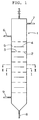
- Fig.1 shows the vertical cross-sectional view of the major portion of the invented contactor.
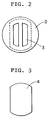
- Fig.2 shows the cross-sectional view of the invented contactor in I - I direction of Fig.1.
- Fig.3 shows the cross-sectional view of the invented contactor in II - II direction of Fig.1.
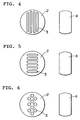
- Fig.4 shows the plan view of an example of a splitter plate and a baffle used in the invented contactor.
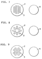
- Figs.5 to 9 are figures similar to Fig.4.
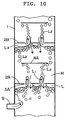
- Fig.10 shows the enlarged vertical sectional view of the major part of the invented contactor aiming at explaining flow droplets.
- Fig.11 shows the mechanism of formation of coalesced droplet layers in the invented contactor.
- the apparatus of the present invention is a liquid-liquid contactor shown in Figs. 1 to 3 in which a heavy liquid is fed from the top of the contactor(1) and a light liquid is fed from the bottom of the contactor so as to contact in continuous counter flow.
- One of the two liquids forms a dispersed phase and the other forms a continuous phase.
- the contactor comprises of a tower shell with splitter plates(2) and baffles (4).
- the splitter plates extending horizontally in the shell have plural slits and/or holes(3) through which the dispersed and continuous phases flow.
- the baffles inserted between splitter plates extend horizontally over the splitter plates to cover the liquid flow paths in the splitter plates, and provide the liquid flow paths(5).
- the aperture ratio of the baffles is larger than that of a splitter plate.
- the important fuction of the splitter plates is that the residence time of the droplets of the dispersed phase is long enough to form coalesced layers under the splitter plates.
- (6) denotes the inlet of a heavy liquid
- (7) denotes the outlet of a light liquid
- (8) denotes the outlet of a heavy liquid
- (9) denotes the inlet of a light liquid.
- splitter plates and baffles Many other different shapes of splitter plates and baffles besides the examples shown in Figs.2 and 3, are possible. Some of those examples are shown in Figs. 4 to 9 where splitter plates and baffles are shown in the left-hand sides, and right-hand sides, respectively.
- the sizes of the aperture for liquid flow depend on the total capacity of the tower, the density difference between the liquids, and liquid viscosities, etc.
- the appropriate width ranges from 10 mm to 30 mm.
- appropriate diameters are 10 mm to 150 mm, especially desirable diameters are 15 to 30 mm.
- the ratio of the cross-sectional area of the open channels of a splitter plate to that of the total tower cross-sectional area ranges from 10 to 40 %.
- the desirable percentages are 20% - 35%.
- the figure illustrated by broken lines shown in Fig. 2 indicates a projection of the baffle (Fig.3) located just over the splitter plate.
- the distance between the splitter plates and the baffles is, determined depending on tower sizes, and properties of the liquids to be contacted to reduce the extent of axial mixing.
- the desirable distance ranges from 30 mm to 500 mm, and the preferable range is 50 mm to 200 mm.
- total superficial velocity of a feed sum of the velocities of the light and heavy liquids, ranges from 0.2 cm/sec to 2 cm/sec.
- Light and heavy liquids to be contacted in the present liquid-liquid contactor may be any combination of two liquids which have low mutual solubilities, and are readily separable.
- Preferable examples of light and heavy liquids are given below:
- a suitable light liquid is selected among acetic acid esters, acrylic acid esters, and methacrylic acid esters.
- these esters are produced from esterification reactions, or ester-exchange reactions of alkyl alcohols of 1 - 10 carbon atoms and one of acetic acid, acrylic acid, and methacrylic acid.
- esters are ethyl acetate, butyl acetate, isobutyl acetate, amyl acetate, methyl acrylate, ethyl acrylate, butyl acrylate, 2-ethylhexyl acrylate, octyl acrylate, nonyl acrylate, butyl methacrylate, 2-ethylhexyl methacrylate, and so on.
- esters such as acetates, acrylates, and methacrylates is carried out by reacting a corresponding acid like acetic acid, acrylic acid, and methacrylic acid with an alcohol by using sulfuric acid, or para-toluene sulfonic acid, or methane sulfonic acid as a catalyst.
- Suitable light liquids to be used in the present invention are mainly esters as noted above, and might include (1) raw materials used during a course of ester production: alcohols, acetic acid, acrylic acid, and methacrylic acid; (2) catalyst, and (3) by-products of esterification. Furthermore, product mixtures coming out of an esterification reactor could be treated as light liquids.
- a sutable heavy liquid is chosen from an aqueous solution containing at least one of acetic acid, acrylic acid and methacrylic acid; an aqueous alkaline solution containing, for instance, caustic soda; and water itself.
- a light liquid(L) contacts a heavy liquid(H) in this liquid-liquid contactor in a manner illustrted in Fig. 10.
- the light liquid(L) introduced into the tower(1) through the light liquid inlet(9) is splitted into many streams by the apertures for liquid flow(3A) in the lower splitter plate(2A), and rises through the heavy liquid(H) as liquid jets.
- the liquid jets of light liquid are broken up into small spherical droplets(L2).
- the droplets reach the baffle plate(4A), and flow radially along the lower surface of the baffle, then rise upward through the open channels of the baffle as droplets(L2).
- the droplets coalesce while moving slowly along the under surface of the second splitter plate(2B) to form coalesced layers(L3).
- Fig. 11 schematically illustrates a manner of formation of coalesced layers(L3) from the droplets(L2) under the splitter plate(2B).
- Droplets(L2) gather and accumulate to form layers of droplets accelerated by mutual contacting of droplets, and form coalesced layers(L3).
- the liquid-liquid contactor of the present invention provides a high liquid-liquid contacting efficiency because of frequent coalescence and breakup of dispersed phase droplets. Since droplets passing through the apertures of the splitter plate become larger than those by the conventional contactors, high liquid flow rates can be attained, thus the present apparatus can produce higher throughputs.
- a heavy liquid is a dispersed phase
- the characteristics of the present invention is also retained except that the dispersed phase flows downward.
- a perforated plate tower made of glass of inner diameter of 100 mm was used as the apparatus for extraction. Each five perforated plates having four holes of 6 mm diameter, is mounted inside the tower at intervals of 150 mm.
- the feedstock is a heavy liquid and the solvent is a light liquid.
- the latter was fed as the dispersed phase, and was contacted with the former at a solvent ratio (solvent/feedstock) of 1.8/1.0 by weight, at 30 °C under atmospheric pressure.
- the flow rate of the raffinate was 33.8 kg/Hr, with acetic acid concentration of 17.5 % and water concentration of 72.9 %.
- the flow rate of the feedstock was increased to 56 kg/Hr,and 101 kg/Hr for the solvent, flooding occurred.
- the number of holes (diameter 6 mm) of the perforated plates was increased from four to eight, and the extraction was repeated.
- the flow rate of the raffinate was 34.6 kg/Hr, with acetic acid concentration of 19.5 % and water concentration 71.0 %.
- the flow rate of the feedstock was increased to 56 kg/Hr, and 101 kg/Hr for the solvent, flooding also occurred.
- a disk-and-doughnut type baffle tower was used as an extraction apparatus.
- the inner diameter of the tower is 100 mm.
- Outer diameter of the disk is 80 mm and inner diameter of the doughnut is 70 mm.
- the intervals between the disks and doughnuts are 75 mm, and the pitches of the disks are 150 mm.
- the number of stages is five: one stage consists of a pair of a disk and a doughnut. Even at the flooding flow rates for the perforated-plate towers mentioned above: 56 kg/Hr feedstock, and 101 kg/Hr solvent, extraction could be carried our in this apparatus.
- the raffinate flow rate was 45.4 kg/Hr with acetic acid concentration of 21.3 %, and water concentration 68.7 %, and the extraction factor and the stage efficiencies were lower than those of the perforated-plate tower as shown in TABLE 2.
- the flow rates of the feedstock and the solvent were increased to 81 kg/Hr and 146 kg/Hr, respectively, flooding occurred.
- TABLE 2 Flow Rates; kg/Hr (space velocity; cm/sec.) Extraction Rate (%) Stage Efficiency (%) Feedstock Solvent 56 (0.20) 101 (0.40) 49 10 81 (0.29) 146 (0.57) flooding occurred
- An extraction apparatus having splitter plates and baffles of the shapes shown in Fig.2 and Fig.3, was used.
- the opening area for passage of the liquids in the splitter plates is 30 %, and that of the baffles is 40 %.
- the intervals between splitter plates and adjacent baffles are 75 mm, and the number of stages (a pair of a splitter plate and a baffle forms one stage) is five.
- the raffinate flow rate was 39.8 kg/Hr with concentrations of acetic acid and water of 14.2 % and 76.6 %, respectively.
- the raffinate contained acetic acid of 12.1 % and water of 79.1 %.
- the stage efficiencies and extraction factors are listed in TABLE 3.
- coalescence and breakup of droplets can not be achieved repeatedly.
- the liquid droplets coalesced under the splitter plates ascend fast through the apertures in the form of large droplets resulting in jets breakup, and then small droplets are generated, and after colliding with the next baffle the droplets coalesce under the next splitter plate.
- the coalesced liquid droplet layers break up to form small droplets again, and such mechanism of coalescence and breakup mentioned above are repeated. It is considered that although large droplets are unfavorable from the view point of contact efficiency, repetition of coalescence and breakup improves the total extraction efficiency. This is the reason why the present invention is superior to the conventional extraction tower of disk-and-doughnut type described in the Comparative Example 2.
- the large droplets give higher superficial velocities of both dispersed and continuous phase. Coalesced layers are formed due to coalescence of the droplets under the splitter plates, and in addition, both the dispersed and the continuous phases flow in plug flow. Therfore, even at a larger scale tower, it is possible to reduce axial mixing, and thereby, the contact efficiency can be maintained high. In other words, performance dependency on scale is weak concerning the present apparatus.
- Butyl methacrylate was prepared by reacting methacrylic acid and n-butyl alcohol. Butyl alcohol and methacrylic acid were mixed at the ratio of 1.2 (mole), and para-toluene sulfonic acid was added to be 0.75 % (by weight) to the mixture as esterification catalyst. The mixture was charged into the reactor, and heated by steam. The reaction temperature was kept at 100 °C by adjusting the pressure in the reactor. Heating was continued until the reaction was completed by distilling all the water formed by the reaction.
- compositions(by weight) of the product were: butyl methacrylate 89.5 %, butyl alcohol 9.9 %, and methacrylic acid 0.5 %.
- the conversion of the methacrylic acid was 99 %.
- Analysis by a liquid chromatography gave the content of para-toluene sulfonic acid of 0.82 %.
- Extraction of para-toluene sulfonic acid was conducted by liquid-liquid contacting using the reaction product as the light liquid(feedstock), and water as the heavy liquid (solvent).
- the flow rates were 183kg/Hr for the light liquid, and 54kg/Hr for water.
- Example 2 183 (0.74) 54 (0.19) 82 23 Comparative Example 3 100 (0.41) 23 (0.08) 71 20* Comparative Example 4 98 (0.40) 29 (0.10) 61 17 164 (0.67) 49 (0.17) flooding occurred * After a continuous operation for 31 hours scum accumulated, and continuous operation became difficult.
Landscapes
- Chemical & Material Sciences (AREA)
- Chemical Kinetics & Catalysis (AREA)
- Extraction Or Liquid Replacement (AREA)
- Physical Or Chemical Processes And Apparatus (AREA)
- Organic Low-Molecular-Weight Compounds And Preparation Thereof (AREA)
Claims (6)
- Flüssigkeits-Flüssigkeits-Kontakteinrichtung vom nichtgerührten Typ, worin eine schwere Flüssigkeit (H) von der Oberseite der Kontakteinrichtung (1) zugeführt wird, und eine leichte Flüssigkeit (L) von der Unterseite der Kontakteinrichtung (1) zugeführt wird, so daß sich beide Flüssigkeiten (H, L) kontinuierlich kontaktieren; wobei eine der beiden Flüssigkeiten (H, L) eine dispergierte Phase bildet und die andere eine kontinuierliche Phase im Gegenstromfluß in der Kontakteinrichtung (1) bildet, worin die Kontakteinrichtung ein Turmgehäuse mit Verteilerplatten (2, 2A, 2B) und Ablenkplatten bzw. Baffles (4, 4A), die abwechselnd in der Axialrichtung in angemessenen Intervallen innerhalb des Gehäuses angebracht sind, umfaßt; wobei jede Verteilerplatte (2, 2A, 2B) Öffnungen (3, 3A) von mehreren Schlitzen und/oder Löchern hat, durch welche sowohl schwere (H) als auch leichte (L) Flüssigkeit gleichzeitig strömt; wobei jede Ablenkplatte bzw. jedes Baffle nichtperforiert ist; wobei der Bereich zwischen der Ablenkplatte bzw. dem Baffle (4, 4A) und dem Turmgehäuse größer als die Fläche der Öffnungen der Verteilerplatte (2, 2A, 2B) ist, die unter der Ablenkplatte bzw. dem Baffle (4, 4A) liegt; wobei die Öffnungen in den Verteilerplatten in einem begrenzten Bereich der Verteilerplatten sind; wobei sich die Ablenkplatten bzw. Baffles in einer Art und Weise des Bedeckens des begrenzten Bereichs der Öffnungen (3, 3A) der Verteilerplatte (2, 2A, 2B) erstrecken und Strömungskanäle (5) für die Flüssigkeiten (H, L), welche durch die Verteilerplatte (2, 2A, 2B) fließen, so vorsehen, daß die Verweilzeit der dispergiertphasigen Flüssigkeit, die sich unter der Verteilerplatte bewegt, lang genug ist, um die koaleszierten Schichten (L3) von Tropfen (L2) zu bilden.
- Flüssigkeits-Flüssigkeits-Kontakteinrichtung nach Anspruch 1, dadurch gekennzeichnet, daß die Schlitze der Verteilerplatten (2, 2A, 2B) die Breite von 5 mm bis 150 mm haben, wobei bevorzugte Breiten 10 mm bis 30 mm sind; und im Falle von Lochöffnungen die wünschbaren Durchmesser 10 mm bis 150 mm, und vorzugsweise 15 mm bis 30 mm, sind.
- Flüssigkeits-Flüssigkeits-Kontakteinrichtung nach Anspruch 1, dadurch gekennzeichnet, daß die Verhältnisse der Öffnungsfläche einer Verteilerplatte (2, 2A, 2B) zu der gesamten Turmquerschnittsfläche 10 % bis 40 % sind, und vorzugsweise 20 % bis 35 % sind.
- Flüssigkeits-Flüssigkeits-Kontakteinrichtung nach Anspruch 1, dadurch gekennzeichnet, daß die Abstände zwischen der Verteilerplatte (2, 2A, 2B) und den Ablenkplatten bzw. Baffles (4, 4A) 30 mm bis 500 mm sind, und vorzugsweise 50 mm bis 200 mm sind.
- Verfahren der Flüssigkeits-Flüssigkeits-Kontaktierung unter Verwendung der Flüssigkeits-Flüssigkeits-Kontakteinrichtung gemäß irgendeinem der Ansprüche 1 bis 4, dadurch gekennzeichnet, daß der Flüssigkeits-Flüssigkeits-Kontaktierungsvorgang unter der Bedingung ausgeführt wird, daß die Gesamtoberflächengeschwindigkeit, die durch die Summe der Oberflächengeschwindigkeiten von schwerer und leichter Flüssigkeit definiert ist, im Bereich von 0,2 cm/s bis 2 cm/s liegt.
- Verfahren der Flüssigkeits-Flüssigkeits-Kontaktierung gemäß Anspruch 5, dadurch gekennzeichnet, daß eine leichte Flüssigkeit esterbasierend ist, ausgewählt unter Essigsäureestern, Acrylsäureestern und Methacrylsäureestern; eine schwere Flüssigkeit ausgewählt ist unter einer wäßrigen Lösung, enthaltend wenigstens eine solcher Säuren wie Essigsäure, Acrylsäure und Methacrylsäure, wäßrige Alkalilösung und Wasser.
Applications Claiming Priority (4)
| Application Number | Priority Date | Filing Date | Title |
|---|---|---|---|
| JP288554/91 | 1991-11-05 | ||
| JP28855491 | 1991-11-05 | ||
| JP253036/92 | 1992-09-22 | ||
| JP4253036A JP2576744B2 (ja) | 1991-11-05 | 1992-09-22 | 液液接触塔 |
Publications (3)
| Publication Number | Publication Date |
|---|---|
| EP0541005A2 EP0541005A2 (de) | 1993-05-12 |
| EP0541005A3 EP0541005A3 (en) | 1993-11-18 |
| EP0541005B1 true EP0541005B1 (de) | 1996-09-04 |
Family
ID=26541008
Family Applications (1)
| Application Number | Title | Priority Date | Filing Date |
|---|---|---|---|
| EP92118498A Expired - Lifetime EP0541005B1 (de) | 1991-11-05 | 1992-10-29 | Flüssig-flüssig-Kontaktapparat |
Country Status (6)
| Country | Link |
|---|---|
| US (1) | US5393429A (de) |
| EP (1) | EP0541005B1 (de) |
| JP (1) | JP2576744B2 (de) |
| BR (1) | BR9204297A (de) |
| DE (1) | DE69213388T2 (de) |
| ES (1) | ES2091992T3 (de) |
Cited By (1)
| Publication number | Priority date | Publication date | Assignee | Title |
|---|---|---|---|---|
| US20070149772A1 (en) * | 2005-12-27 | 2007-06-28 | Shin-Etsu Chemical Co., Ltd. | Methods for preparing alkali cellulose and cellulose ether |
Families Citing this family (41)
| Publication number | Priority date | Publication date | Assignee | Title |
|---|---|---|---|---|
| US5500116A (en) * | 1993-07-19 | 1996-03-19 | Jgc Corporation | Liquid-liquid contactor |
| JP3568953B2 (ja) | 1993-07-30 | 2004-09-22 | アルバ・インターナショナル・プロプライアタリ・リミテッド | 血漿脱脂肪システム |
| AUPN030794A0 (en) | 1994-12-22 | 1995-01-27 | Aruba International Pty Ltd | Discontinuous plasma or serum delipidation |
| US5641462A (en) * | 1995-07-12 | 1997-06-24 | University Of Utah | Continuous solvent extraction with bottom gas injection |
| DE69717504T2 (de) * | 1997-04-07 | 2004-02-26 | Claude Charzat | Verfahren und apparat zur auflösung einer mischung |
| US6056128A (en) * | 1998-08-04 | 2000-05-02 | Glasgow; James A. | Coalescer with removable cartridge |
| US7407663B2 (en) | 2000-06-29 | 2008-08-05 | Lipid Sciences, Inc. | Modified immunodeficiency virus particles |
| US7407662B2 (en) * | 2000-06-29 | 2008-08-05 | Lipid Sciences, Inc. | Modified viral particles with immunogenic properties and reduced lipid content |
| AUPQ846900A0 (en) * | 2000-06-29 | 2000-07-27 | Aruba International Pty Ltd | A vaccine |
| US20090017069A1 (en) * | 2000-06-29 | 2009-01-15 | Lipid Sciences, Inc. | SARS Vaccine Compositions and Methods of Making and Using Them |
| US7439052B2 (en) * | 2000-06-29 | 2008-10-21 | Lipid Sciences | Method of making modified immunodeficiency virus particles |
| US6471865B1 (en) * | 2000-10-25 | 2002-10-29 | Fina Technology, Inc. | Solvent exchange column and a method of use therefor |
| US6991727B2 (en) | 2001-06-25 | 2006-01-31 | Lipid Sciences, Inc. | Hollow fiber contactor systems for removal of lipids from fluids |
| US20060060520A1 (en) * | 2001-06-25 | 2006-03-23 | Bomberger David C | Systems and methods using a solvent for the removal of lipids from fluids |
| EP1412045A4 (de) * | 2001-06-25 | 2007-05-02 | Lipid Sciences Inc | Ein lösungsmittel zur entfernung von lipiden aus fluiden verwendende systeme und verfahren |
| US20030127386A1 (en) * | 2001-06-25 | 2003-07-10 | Bomberger David C. | Hollow fiber contactor systems for removal of lipids from fluids |
| WO2003000372A2 (en) * | 2001-06-25 | 2003-01-03 | Lipid Sciences, Inc. | Systems and methods using multiple solvents for the removal of lipids from fluids |
| WO2004017946A1 (en) * | 2002-08-26 | 2004-03-04 | Lipid Sciences, Inc. | Treating alzheimers using delipidated protein particles |
| JP2007527387A (ja) * | 2003-07-03 | 2007-09-27 | リピッド サイエンシーズ,インコーポレイテッド | 脂質含量の低下したhdlの粒子誘導体を製造するための方法及び装置 |
| US7393826B2 (en) * | 2003-07-03 | 2008-07-01 | Lipid Sciences, Inc. | Methods and apparatus for creating particle derivatives of HDL with reduced lipid content |
| US6960803B2 (en) * | 2003-10-23 | 2005-11-01 | Silicon Storage Technology, Inc. | Landing pad for use as a contact to a conductive spacer |
| EP1685852A1 (de) * | 2005-02-01 | 2006-08-02 | Fondation pour la Recherche Diagnostique | Set von Einwegbeuteln zur Virusinaktivierung von biologischen Fluids |
| JP5410044B2 (ja) * | 2007-08-16 | 2014-02-05 | 日揮株式会社 | 接触塔及び処理方法 |
| RU2446872C2 (ru) * | 2007-08-16 | 2012-04-10 | ДжейДжиСи КОРПОРЕЙШН | Контактор |
| NO330928B1 (no) * | 2009-01-13 | 2011-08-22 | Elkem Solar As | Apparat og fremgangsmate for behandling av ublandbare vaesker |
| CN102276470A (zh) * | 2010-06-08 | 2011-12-14 | 中国石油化工集团公司 | 连续逆流硝化芳烃化合物的方法 |
| FR2998190B1 (fr) * | 2012-11-20 | 2015-10-16 | Ifp Energies Now | Colonne d'extraction liquide liquide comportant deux types de plateaux distincts |
| US9308470B2 (en) | 2013-03-12 | 2016-04-12 | The Chem-Pro Group Llc | Liquid-liquid extractor |
| GB2517157B (en) * | 2013-08-12 | 2016-05-25 | Bateman Advanced Tech Ltd | Contacting Arrangement |
| FR3010998B1 (fr) * | 2013-09-23 | 2016-11-25 | Arkema France | Procede d'extraction liquide - liquide pour la production d'esters acryliques |
| CN103599740B (zh) * | 2013-11-28 | 2015-07-29 | 临沂远博化工有限公司 | 一种硝基甲烷合成反应塔 |
| US20160031770A1 (en) * | 2014-07-29 | 2016-02-04 | Honeywell International Inc. | Reactor with baffle configuration |
| CN105903228B (zh) * | 2016-06-03 | 2017-11-14 | 浙江大学 | 一种隔壁双层板式环流萃取塔和萃取的方法 |
| US11358878B2 (en) | 2016-11-14 | 2022-06-14 | William H. Mitchell, JR. | Systems and methods for separating soluble solutions |
| US11813581B2 (en) | 2017-07-14 | 2023-11-14 | 3M Innovative Properties Company | Method and adapter for conveying plural liquid streams |
| AU2018372198A1 (en) | 2017-11-22 | 2020-06-11 | Hdl Therapeutics, Inc. | Systems and methods for priming fluid circuits of a plasma processing system |
| CN112040932A (zh) | 2017-12-28 | 2020-12-04 | Hdl治疗公司 | 一种保存和给药自人类血浆提取的前-β高密度脂蛋白的方法 |
| US20200147543A1 (en) | 2018-11-08 | 2020-05-14 | Exxonmobil Research And Engineering Company | Porous liquid, self-replenishing porous liquid and methods of making and using the same |
| US11439927B2 (en) | 2018-11-08 | 2022-09-13 | ExxonMobil Technology and Engineering Company | Species extraction |
| CN112156497B (zh) * | 2020-09-28 | 2021-10-12 | 南方医科大学 | 一种用于富集痕量分析物的非水互溶两相的液-液电萃取装置及其应用 |
| FR3153539B1 (fr) * | 2023-09-29 | 2025-10-24 | Commissariat Energie Atomique | Colonne pulsée pour l’extraction liquide-liquide avec garnissage |
Family Cites Families (13)
| Publication number | Priority date | Publication date | Assignee | Title |
|---|---|---|---|---|
| US2153507A (en) * | 1932-02-26 | 1939-04-04 | Standard Oil Dev Co | Immiscible liquid countercurrent method and apparatus |
| US2794711A (en) * | 1955-11-17 | 1957-06-04 | Exxon Research Engineering Co | Liquid-liquid countercurrent contacting device |
| US3521756A (en) * | 1968-06-17 | 1970-07-28 | Cities Service Athabasca Inc | Coalescing vessel |
| US3658484A (en) * | 1969-10-24 | 1972-04-25 | Arthur W Bright | Countercurrent contact apparatus |
| BE779267A (fr) * | 1969-11-17 | 1972-08-11 | Rohm & Haas | Procede pour accelerer la separation de deux phases liquides dans l'extraction d'acide acrylique aqueux |
| JPS538663B2 (de) * | 1971-11-30 | 1978-03-30 | ||
| US3826740A (en) * | 1972-05-30 | 1974-07-30 | W Jewett | Method and apparatus for treating multi-phase systems |
| US3878094A (en) * | 1972-11-27 | 1975-04-15 | Fram Corp | System for separating hydrocarbons from water |
| US4305907A (en) * | 1978-12-18 | 1981-12-15 | Artisan Industries, Inc. | Liquid-liquid extraction apparatus |
| US4275032A (en) * | 1979-07-12 | 1981-06-23 | Uop Inc. | Alkylation combined settler-soaker apparatus |
| US4588563A (en) * | 1984-01-13 | 1986-05-13 | Exxon Research And Engineering Co. | Cascade sieve tray for extraction and deasphalting |
| US4982653A (en) * | 1987-07-10 | 1991-01-08 | Saddle Vent, Inc. | Method and apparatus for ventilating an enclosure accessed by a manhole |
| HU209706B (en) * | 1989-07-20 | 1994-10-28 | Richter Gedeon Vegyeszet | Equipment for the contacting of fluids of different density |
-
1992
- 1992-09-22 JP JP4253036A patent/JP2576744B2/ja not_active Expired - Lifetime
- 1992-10-29 ES ES92118498T patent/ES2091992T3/es not_active Expired - Lifetime
- 1992-10-29 EP EP92118498A patent/EP0541005B1/de not_active Expired - Lifetime
- 1992-10-29 DE DE69213388T patent/DE69213388T2/de not_active Expired - Lifetime
- 1992-11-02 US US07/970,132 patent/US5393429A/en not_active Expired - Lifetime
- 1992-11-05 BR BR929204297A patent/BR9204297A/pt not_active IP Right Cessation
Cited By (2)
| Publication number | Priority date | Publication date | Assignee | Title |
|---|---|---|---|---|
| US20070149772A1 (en) * | 2005-12-27 | 2007-06-28 | Shin-Etsu Chemical Co., Ltd. | Methods for preparing alkali cellulose and cellulose ether |
| US8853388B2 (en) * | 2005-12-27 | 2014-10-07 | Shin-Etsu Chemical Co., Ltd. | Methods for preparing alkali cellulose and cellulose ether |
Also Published As
| Publication number | Publication date |
|---|---|
| US5393429A (en) | 1995-02-28 |
| EP0541005A2 (de) | 1993-05-12 |
| JPH0655063A (ja) | 1994-03-01 |
| BR9204297A (pt) | 1993-05-11 |
| ES2091992T3 (es) | 1996-11-16 |
| JP2576744B2 (ja) | 1997-01-29 |
| EP0541005A3 (en) | 1993-11-18 |
| DE69213388T2 (de) | 1997-01-23 |
| DE69213388D1 (de) | 1996-10-10 |
Similar Documents
| Publication | Publication Date | Title |
|---|---|---|
| EP0541005B1 (de) | Flüssig-flüssig-Kontaktapparat | |
| EP0635293B1 (de) | Flüssig-flüssig-Kontaktvorrichtung | |
| RU95121590A (ru) | Многостадийный способ суспензионной реакционной отпарки и устройство для его осуществления | |
| EP1057509A1 (de) | Vorrichtung und Verfahren zur Reinigung von leicht blockierende Substanzen enthaltenden organischen Stoffen | |
| CN101618304B (zh) | 一种酯化反应器 | |
| EP1387720B1 (de) | Reaktor für gas/flüssig- oder gas/flüssig/fest-reaktionen | |
| US6029956A (en) | Predominantly liquid filled vapor-liquid chemical reactor | |
| US4588563A (en) | Cascade sieve tray for extraction and deasphalting | |
| RU2147922C1 (ru) | Реактор для жидкофазных процессов окисления углеводородов | |
| US4200525A (en) | Liquid extraction process and apparatus for accomplishing the same | |
| US5421972A (en) | Process and apparatus for removing soluble contaminants from hydrocarbon streams | |
| CA1070879A (en) | Continuous latex stripping method | |
| KR100897078B1 (ko) | 말레산 무수물의 흡수를 위해 사용된 유기 용매를정제하는 방법 | |
| US6075169A (en) | Process for preparing oxidation products from cyclohexane in counterflow | |
| JP2679630B2 (ja) | 堰板型液液接触塔 | |
| EP0058074B1 (de) | Verfahren zur Flüssig-Flüssig-Extraktion | |
| JPS598281B2 (ja) | 塩化ビニルポリマ−含有スラリ−から塩化ビニルモノマ−を除去する適当な気液接触塔 | |
| CN222342012U (zh) | 一种连续化生产用汽提塔 | |
| US4865697A (en) | Flashing feed inlet in a vapor/liquid contacting tower and method | |
| US3246026A (en) | Manufacturing of sulphated and sulphonated prouducts | |
| CN102908956B (zh) | 一种酯化反应器及马来酸二甲酯的生产方法 | |
| JPS59122452A (ja) | 尿素合成管 | |
| KR100538191B1 (ko) | 역류접촉에 의한 시클로헥산 산화 생성물의 제조 방법 | |
| SU893242A1 (ru) | Пр моточный реактор | |
| SU1017360A1 (ru) | Вибрационный массообменный колонный аппарат |
Legal Events
| Date | Code | Title | Description |
|---|---|---|---|
| PUAI | Public reference made under article 153(3) epc to a published international application that has entered the european phase |
Free format text: ORIGINAL CODE: 0009012 |
|
| AK | Designated contracting states |
Kind code of ref document: A2 Designated state(s): BE DE ES FR GB IT NL |
|
| PUAL | Search report despatched |
Free format text: ORIGINAL CODE: 0009013 |
|
| AK | Designated contracting states |
Kind code of ref document: A3 Designated state(s): BE DE ES FR GB IT NL |
|
| 17P | Request for examination filed |
Effective date: 19940210 |
|
| 17Q | First examination report despatched |
Effective date: 19941122 |
|
| RAP1 | Party data changed (applicant data changed or rights of an application transferred) |
Owner name: MITSUBISHI CHEMICAL CORPORATION Owner name: JGC CORPORATION |
|
| GRAH | Despatch of communication of intention to grant a patent |
Free format text: ORIGINAL CODE: EPIDOS IGRA |
|
| GRAA | (expected) grant |
Free format text: ORIGINAL CODE: 0009210 |
|
| GRAH | Despatch of communication of intention to grant a patent |
Free format text: ORIGINAL CODE: EPIDOS IGRA |
|
| AK | Designated contracting states |
Kind code of ref document: B1 Designated state(s): BE DE ES FR GB IT NL |
|
| ITF | It: translation for a ep patent filed | ||
| ET | Fr: translation filed | ||
| REF | Corresponds to: |
Ref document number: 69213388 Country of ref document: DE Date of ref document: 19961010 |
|
| REG | Reference to a national code |
Ref country code: ES Ref legal event code: FG2A Ref document number: 2091992 Country of ref document: ES Kind code of ref document: T3 |
|
| PLBE | No opposition filed within time limit |
Free format text: ORIGINAL CODE: 0009261 |
|
| STAA | Information on the status of an ep patent application or granted ep patent |
Free format text: STATUS: NO OPPOSITION FILED WITHIN TIME LIMIT |
|
| 26N | No opposition filed | ||
| REG | Reference to a national code |
Ref country code: GB Ref legal event code: IF02 |
|
| PGFP | Annual fee paid to national office [announced via postgrant information from national office to epo] |
Ref country code: DE Payment date: 20101027 Year of fee payment: 19 |
|
| PGFP | Annual fee paid to national office [announced via postgrant information from national office to epo] |
Ref country code: IT Payment date: 20101022 Year of fee payment: 19 Ref country code: GB Payment date: 20101027 Year of fee payment: 19 |
|
| PGFP | Annual fee paid to national office [announced via postgrant information from national office to epo] |
Ref country code: BE Payment date: 20111012 Year of fee payment: 20 Ref country code: FR Payment date: 20111103 Year of fee payment: 20 Ref country code: ES Payment date: 20111021 Year of fee payment: 20 Ref country code: NL Payment date: 20111020 Year of fee payment: 20 |
|
| REG | Reference to a national code |
Ref country code: DE Ref legal event code: R071 Ref document number: 69213388 Country of ref document: DE |
|
| REG | Reference to a national code |
Ref country code: DE Ref legal event code: R071 Ref document number: 69213388 Country of ref document: DE |
|
| BE20 | Be: patent expired |
Owner name: *JGC CORP. Effective date: 20121029 Owner name: *MITSUBISHI CHEMICAL CORP. Effective date: 20121029 |
|
| REG | Reference to a national code |
Ref country code: NL Ref legal event code: V4 Effective date: 20121029 |
|
| REG | Reference to a national code |
Ref country code: GB Ref legal event code: PE20 Expiry date: 20121028 |
|
| PG25 | Lapsed in a contracting state [announced via postgrant information from national office to epo] |
Ref country code: GB Free format text: LAPSE BECAUSE OF EXPIRATION OF PROTECTION Effective date: 20121028 |
|
| REG | Reference to a national code |
Ref country code: ES Ref legal event code: FD2A Effective date: 20130718 |
|
| PG25 | Lapsed in a contracting state [announced via postgrant information from national office to epo] |
Ref country code: ES Free format text: LAPSE BECAUSE OF EXPIRATION OF PROTECTION Effective date: 20121030 |