EP0540830A1 - Verfahren und Vorrichtung zur Entfernung von Partikeln aus Behältern - Google Patents
Verfahren und Vorrichtung zur Entfernung von Partikeln aus Behältern Download PDFInfo
- Publication number
- EP0540830A1 EP0540830A1 EP92113432A EP92113432A EP0540830A1 EP 0540830 A1 EP0540830 A1 EP 0540830A1 EP 92113432 A EP92113432 A EP 92113432A EP 92113432 A EP92113432 A EP 92113432A EP 0540830 A1 EP0540830 A1 EP 0540830A1
- Authority
- EP
- European Patent Office
- Prior art keywords
- containers
- particles
- air
- low pressure
- cap
- Prior art date
- Legal status (The legal status is an assumption and is not a legal conclusion. Google has not performed a legal analysis and makes no representation as to the accuracy of the status listed.)
- Withdrawn
Links
Images


Classifications
-
- B—PERFORMING OPERATIONS; TRANSPORTING
- B07—SEPARATING SOLIDS FROM SOLIDS; SORTING
- B07B—SEPARATING SOLIDS FROM SOLIDS BY SIEVING, SCREENING, SIFTING OR BY USING GAS CURRENTS; SEPARATING BY OTHER DRY METHODS APPLICABLE TO BULK MATERIAL, e.g. LOOSE ARTICLES FIT TO BE HANDLED LIKE BULK MATERIAL
- B07B7/00—Selective separation of solid materials carried by, or dispersed in, gas currents
-
- B—PERFORMING OPERATIONS; TRANSPORTING
- B08—CLEANING
- B08B—CLEANING IN GENERAL; PREVENTION OF FOULING IN GENERAL
- B08B5/00—Cleaning by methods involving the use of air flow or gas flow
- B08B5/02—Cleaning by the force of jets, e.g. blowing-out cavities
Definitions
- This invention generally relates to methods and apparatus for extracting particles from containers; and more specifically, to such methods and apparatus that are particularly well suited for extracting particles from breakable food containers.
- the present invention relates to a method and apparatus for extracting particles from containers.
- the method comprises the steps of conducting high pressure air from a source thereof and into the containers to free any particles from the container walls, and connecting the containers to a low pressure source to withdraw air and the now loose particles from the containers.
- the apparatus comprises a source of pressurized air and a high pressure line connected to that source to conduct the pressurized air to the containers to loosen the particles from the containers.
- the apparatus further comprises a low pressure source, and a low pressure line to connect the containers to the low pressure source to withdraw air and the particles from the containers.
- the containers are moved beneath one or more caps that are used to generally close the tops of the containers, and each cap is connected to both the high and low pressure sources.
- Figure 1 is a flow diagram illustrating a preferred particle extraction method and apparatus of this invention.
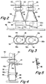
- Figure 2 is a side elevation view of two container caps of the system shown in Figure 1.
- Figure 3 is a bottom view of the caps shown in Figure 2.
- Figure 4 is a side cross-section view through one of the container caps illustrated in Figure 2.
- Figure 5 is an enlarged view of a portion of Figure 4.
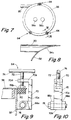
- Figure 6 is a side elevation view of the particle separator used in the system of Figure 1.
- Figure 7 is a top plan view of the particle separator.
- Figure 8 is an enlarged cross-sectional view of a portion of the particle separator, taken along Line VIII-VIII of Figure 6.
- Figure 9 shows one of the connecting assemblies of the particle separator and is taken along Line IX-IX of Figure 7.
- Figure 10 is a side view of the connecting assembly shown in Figure 9.
- Figure 1 illustrates particle extraction system 10 generally comprising a source 12 of high pressure air, high pressure lines 14 and 16, low pressure lines 20, 22, 24, and 26, and a low-pressure source 30, and preferably system 10 further comprises a pair of caps 32 and 34 and particle separator 36.
- Figure 1 also schematically shows a multitude of containers 40 mounted on conveyor belt 42 that carries the containers past extraction system 10, specifically caps 32 and 34.
- System 10 is particularly well suited for use in conjunction with a food processing or handling system in which, among other things, containers 40 are filled with a food product or material.
- containers 40 are filled with a food product or material.
- the related food processing or handling system is not shown in the drawings.
- system 10 is provided to remove those broken fragments or pieces from the container 40.
- containers are moved past the extraction system, specifically caps 32 and 34.
- high pressure lines 14 and 16 are used to conduct pressurized air from source 12 into containers 40 to loosen any particles that might be in the container, and then low pressure lines 20, 22, 24, and 26 are is used to connect the containers to low pressure source 30 to withdraw from the containers 40 air and any particle fragments that might be in the containers.
- each cap 32, 34 is connected to one of the low pressure lines and one of the high pressure lines; and as containers 40 move along conveyor 42, each container comes directly beneath one or both of the caps 32, 34, with the top, open end of each container coming immediately below the bottom open end of one or both of the caps.
- each time one of the containers is located directly below one of the caps first, high pressure air is conducted through a high pressure line, through that one cap, and into the container below that cap, and second, one of the low pressure lines is used to draw any particles out from that container.
- each container 40 is moved beneath both caps 32 and 34 in series, and both caps are used to extract particles from each of the containers.
- system 10 may be provided with only one cap, with a single high pressure line connecting that cap to high pressure source 12, and with a single low pressure line connecting that cap to low pressure source 30.
- the containers 40 move continuously past the caps 32 and 34, although this also is not necessary; and, if desired, each container may be temporarily stopped for a short period of time directly below one or both of the caps. If the containers are stopped below caps 32 and 34, then it may be desirable to mount the caps directly on, or to connect the caps releasably to, the containers.
- each cap 32, 34 preferably includes a side wall and, in addition, a pair of baffles 44 and 46 are connected to opposite, lateral sides of the caps.
- the side wall of each cap has the general shape of a truncated cone, although, as particularly shown in Figure 3, the horizontal cross sections of the caps have an approximately elongated elliptical shape.
- Each cap includes top and bottom openings; and the top and bottom openings of cap 32 are referenced at 32a and 32b, respectively, while the top and bottom openings of cap 34 are referenced at 34a and 34b, respectively.
- a respective one of the low pressure lines is connected to the top opening of each cap, around that top opening; and in particular, line 20 is connected to cap 32 around opening 32a, and line 22 is connected to cap 34 around opening 34a.
- each cap is located at a level slightly above the tops of containers 40 as those containers move past the caps.
- a respective one of the high pressure lines 14, 16 extends through the side wall of each of the caps 32, 34 and into the interior thereof, and each of the high pressure lines includes a downwardly extending forward outlet portion 14a, 16a to direct the high pressure air downward into a container moving beneath the cap.
- the outlet of each high pressure line is centered inside each cap at a position that is, relative to the direction in which containers 40 move past caps 32 and 34, rearward of the center of the cap; and the inlet of each low pressure line is centered at a position that is, again relative to the direction in which containers 40 move past caps 32 and 34, slightly forward of the center of the cap.
- Baffles 44 and 46 are connected to lower portions of caps 32 and 34 and extend downward therefrom, on both sides of the path of travel of containers 40 past the caps, to help enclose those containers as they move beneath the caps. In this way, Baffles 44 and 46 help to increase, first, the efficiency with which the high pressure air loosens any particles in containers 40, and second, the efficiency with which low pressure lines 20 and 22 draw any such particles from the containers.
- a plate 50 is preferably connected to lower portions of low pressure lines 20 and 22, at a location slightly above the inlets thereof. Plate 50 may be connected to an adjacent support member to hold the lower portions of lines 20 and 22 and caps 32 and 34 in place relative to conveyor 42, or plate 50 may be used to move the lower portions of lines 20 and 22 and caps 32 and 34.
- separator 36 is located between containers 40 and low pressure source 30 to receive air and any withdraw particle fragments from containers 40, and to separate those particles from that received air; and, generally, separator 36 includes upper section 52, lower section 54, top cover 56, particle outlet 60, and a plurality of legs 62.
- Upper separator section has the shape of a hollow cylinder
- lower separator section 54 has the shape of a hollow, truncated cone.
- the lower edge 52a of section 52 and the upper edge 54a of section 54 are coterminus and are connected together, and the lower separator section extends downward from the upper separator section coaxial therewith.
- Bottom edge 54b of lower section 54 defines an outlet to discharge particles from the lower separator section, and discharge tube 60 is connected to lower separator section, around that outlet, to conduct particles therefrom.
- Legs 62 are connected to and are spaced around lower separator section 54 and extend downward therefrom to the ground, floor, or another surface to support the particle separator 36 thereon.
- An adjusting bolt may be provided at the bottom end of each leg 62 to allow the height of each leg to be adjusted to help insure that separator 36 is maintained in the preferred orientation --preferably, with the axis of the separator substantially vertical.
- Upper separator section 52 forms two inlets 52c and 52d and each of the low pressure lines 20 and 22 is connected to the upper separator section, around a respective one of those inlets 52c and 52d, to conduct particles and air into the particle separator from containers 40.
- each of the low pressure lines 20 and 22 is connected to upper separator section 52 substantially tangential thereto, so that the low pressure line conducts air and particles into the upper separator section in a direction substantially tangential thereto.
- Cover plate 56 is provided to substantially close the top of upper separator section 52, and this cover plate also forms outlets 56a and 56b for discharging air from the particle separator. More specifically, cover plate 56 has a substantially flat disc-shape and is mounted and supported on top edge 52b of upper separator section 52, and the cover plate extends across that edge, substantially perpendicular to the axis of particle separator 36. Low pressure lines 24 and 26 are connected to cover plate 56, around outlets 56a and 56b, respectively.
- Plate 56 is releasably connected to upper separator section 52, and any suitable means may be employed to do this.
- a plurality of connecting assemblies 64 may be connected to upper separator section 52, adjacent and spaced around upper edge 52b thereof, to releasably hold cover plate 56 thereon.
- each assembly 64 includes a pair of connecting arms 66a and 66b, a hook member 70, clamping bolt 72, and handle 74.
- Arms 66a and 66b are rigidly connected to upper separator section 52, adjacent and spaced below top edge 52b thereof, and arms 66a and 66b extend outward from separator section 52, parallel to each other.
- a bolt 76 is connected to and extends across arms 66a and 66b, and hook member 70 is mounted on bolt 76 for pivotal movement toward and away from top edge 52b of separator section 52.
- Hook member 70 has the shape of a backwards "C", and includes top and bottom leg portions 70a and 70b and base portion 70c. More specifically, top and bottom leg portions 70a and 70b are connected to and extend outward from top and bottom ends, respectively, of base portion 70c. Bottom leg portion 70b forms a through opening and is pivotally mounted on bolt 76, which extends through that through opening. Top leg portion 70a forms a threaded through opening 70d, and clamping bolt 72 extends through that opening and engages the threads thereof. Handle 74 is connected to bolt 72 to rotate the bolt and thereby to move the bolt through opening 70d.
- Hook member 70 is pivotally supported by bolt 76 for pivotal movement between a position, shown in Figure 9, in which upper leg portion 70a and bolt 72 extend over plate 56, and a position in which the upper leg portion 70a and bolt 72 do not project over cover plate 56 or over top edge 52b of upper separator section 52.
- the hooks 70 of the clamping assemblies 64 are pivoted away from edge 52b, and then the cover plate is simply placed on that top edge.
- a resilient seal 80 may extend around section 52, at or immediately inside top edge 52b thereof to help develop an airtight seal between upper separator section 52 and cover plate 56 and to facilitate mounting and securing the cover plate on upper separator section.
- the low pressure in the particle separator forces air and any foreign particles in containers 40 to pass through lines 20 and 22 and into the particle separator, and these particles and air enter the separator 36 along a direction tangential to separator section 52; and then particles and air tend to move around the interior of separator, against section 52. Because of their relatively heavy weight, the particles also tend to move downward in the particle separator 36 and eventually pass outward therefrom through outlet 60; while because of its relatively lighter weight, the air conducted into the particle separator tends to move upward and pass outward therefrom through air outlets 56a and 56b.
- any suitable means 12 may be employed to produce or to supply the desired high pressure air and, likewise, any suitable means 30 may be used to provide the desired low pressure source.
- means 12 may comprise a pump or simply a container holding a supply of air at an elevated pressure
- means 30 may comprise a pair of vacuum pumps connected to particle separator 36 via lines 24 and 26.
- high pressure air may be continuously conducted through lines 14 and 16, and air may be continuously drawn from caps 32 and 34 via lines 20 and 22.
- high pressure air may be supplied through lines 14 and 16 and air may be drawn through lines 20 and 22 at discrete intervals.
- air may be conducted through lines 14 and 16 at intervals coinciding with the movement of containers 40 beneath caps 32 and 34.
Landscapes
- Basic Packing Technique (AREA)
- Sealing Of Jars (AREA)
- Air Transport Of Granular Materials (AREA)
- Cleaning In General (AREA)
- Combined Means For Separation Of Solids (AREA)
Applications Claiming Priority (2)
| Application Number | Priority Date | Filing Date | Title |
|---|---|---|---|
| US07/745,644 US5279017A (en) | 1991-08-15 | 1991-08-15 | Method and apparatus for extracting particles from containers |
| US745644 | 1991-08-15 |
Publications (1)
| Publication Number | Publication Date |
|---|---|
| EP0540830A1 true EP0540830A1 (de) | 1993-05-12 |
Family
ID=24997608
Family Applications (1)
| Application Number | Title | Priority Date | Filing Date |
|---|---|---|---|
| EP92113432A Withdrawn EP0540830A1 (de) | 1991-08-15 | 1992-08-06 | Verfahren und Vorrichtung zur Entfernung von Partikeln aus Behältern |
Country Status (8)
| Country | Link |
|---|---|
| US (1) | US5279017A (de) |
| EP (1) | EP0540830A1 (de) |
| JP (1) | JPH05245459A (de) |
| KR (1) | KR930003975A (de) |
| CN (1) | CN1069462A (de) |
| AU (1) | AU649862B2 (de) |
| CA (1) | CA2074795C (de) |
| NZ (1) | NZ243776A (de) |
Cited By (1)
| Publication number | Priority date | Publication date | Assignee | Title |
|---|---|---|---|---|
| ES2554560R1 (es) * | 2013-04-22 | 2016-02-11 | Hermann Linder | Disposición y procedimiento de limpieza de un recipiente de almacenamiento de material para la técnica de transporte |
Families Citing this family (15)
| Publication number | Priority date | Publication date | Assignee | Title |
|---|---|---|---|---|
| JP2567191Y2 (ja) * | 1992-04-13 | 1998-03-30 | 株式会社伸興 | パネル体の除塵装置 |
| US5487200A (en) * | 1994-01-24 | 1996-01-30 | Herzog; Kenneth J. | Bottle cleaner |
| US5546631A (en) * | 1994-10-31 | 1996-08-20 | Chambon; Michael D. | Waterless container cleaner monitoring system |
| US5711821A (en) * | 1995-04-13 | 1998-01-27 | Texas Instruments Incorporated | Cleansing process for wafer handling implements |
| US5839455A (en) * | 1995-04-13 | 1998-11-24 | Texas Instruments Incorporated | Enhanced high pressure cleansing system for wafer handling implements |
| US5881429A (en) * | 1996-11-06 | 1999-03-16 | Kalish Canada Inc. | Portable container cleaning station |
| US6497000B1 (en) * | 1999-09-30 | 2002-12-24 | Novartis Ag | Apparatus for cleaning ophthalmic components |
| US7520020B1 (en) * | 2004-07-15 | 2009-04-21 | Hutchens Jack L | Apparatus for cleaning a beverage can's top |
| US7937799B2 (en) * | 2006-09-19 | 2011-05-10 | Mark Aaron Riggs | Container cleaning machine |
| US8147616B2 (en) * | 2007-10-22 | 2012-04-03 | Stokely-Van Camp, Inc. | Container rinsing system and method |
| US9168569B2 (en) | 2007-10-22 | 2015-10-27 | Stokely-Van Camp, Inc. | Container rinsing system and method |
| KR101223560B1 (ko) * | 2010-06-24 | 2013-01-17 | 삼성에스디아이 주식회사 | 이차 전지 캔의 이물질 제거 장치 |
| WO2015054204A1 (en) * | 2013-10-07 | 2015-04-16 | Micro Measurement Laboratories, Inc. | Challenge sets and methods of making and using the same |
| CN106425787A (zh) * | 2016-08-31 | 2017-02-22 | 天通银厦新材料有限公司 | 一种蓝宝石打磨磨光一体装置 |
| EP3800132A1 (de) * | 2019-10-04 | 2021-04-07 | Tetra Laval Holdings & Finance S.A. | Vorrichtung zum entfernen von teilchen für eine füllmaschine |
Citations (7)
| Publication number | Priority date | Publication date | Assignee | Title |
|---|---|---|---|---|
| GB724965A (en) * | 1952-03-26 | 1955-02-23 | White Cap Co | Improvements in or relating to pneumatic cleaning of open-topped containers |
| US3915739A (en) * | 1974-07-12 | 1975-10-28 | Montreal | Method of cleaning foreign matter from a cavity in a semiconductor |
| DE2439069A1 (de) * | 1974-08-14 | 1976-02-26 | Schladofsky Leopold | Einrichtung zum aufnehmen und entfernen von grobem schmutz und abfaellen |
| US4017330A (en) * | 1976-02-27 | 1977-04-12 | Aidlin Samuel S | Method and apparatus for internal spray cleaning of containers |
| FR2464222A1 (fr) * | 1979-09-05 | 1981-03-06 | Dolle Marcel | Souffleuse depackeuse de flacons |
| DE3108912A1 (de) * | 1981-03-09 | 1982-09-16 | Hamba-Maschinenfabrik Hans A.Müller GmbH & Co KG, 5600 Wuppertal | Verfahren zur entfernung loser partikel aus bechern und vorrichtung zur durchfuehrung des verfahrens |
| WO1988008402A1 (en) * | 1987-04-24 | 1988-11-03 | Ab Centralsug | A method of and an installation for removing and transferring refuse |
Family Cites Families (11)
| Publication number | Priority date | Publication date | Assignee | Title |
|---|---|---|---|---|
| US3268942A (en) * | 1966-08-30 | Suction cleaning nozzle | ||
| US1448255A (en) * | 1919-05-29 | 1923-03-13 | Capell Lab Inc | Process of canning and canning machine |
| US1880257A (en) * | 1930-07-21 | 1932-10-04 | James A Rheinstrom | Method of cleaning bottles |
| US2073746A (en) * | 1933-02-24 | 1937-03-16 | Best Foods Inc | Bottle cleaning device |
| US2644188A (en) * | 1952-03-26 | 1953-07-07 | White Cap Co | Pneumatic container cleaning apparatus |
| US2917768A (en) * | 1957-05-08 | 1959-12-22 | Fearn Foods Inc | Air cleaning machine for containers |
| US3484890A (en) * | 1968-03-12 | 1969-12-23 | William H Case | Pressure-vacuum cleaning and treating device |
| BE794510A (fr) * | 1972-01-28 | 1973-05-16 | World Inventions Ltd | Perfectionnements apportes aux aspirateurs |
| US4162149A (en) * | 1978-01-03 | 1979-07-24 | Mekelburg Clayton G | Gravel and dust separator and container for vacuum cleaning systems |
| US4872920A (en) * | 1987-11-25 | 1989-10-10 | Flynn Tom S | Asbestos removal method and system |
| US5099542A (en) * | 1990-07-30 | 1992-03-31 | The Boeing Company | Honeycomb core dust removal system |
-
1991
- 1991-08-15 US US07/745,644 patent/US5279017A/en not_active Expired - Fee Related
-
1992
- 1992-07-28 CA CA002074795A patent/CA2074795C/en not_active Expired - Fee Related
- 1992-07-30 NZ NZ243776A patent/NZ243776A/en unknown
- 1992-08-06 EP EP92113432A patent/EP0540830A1/de not_active Withdrawn
- 1992-08-07 AU AU20906/92A patent/AU649862B2/en not_active Ceased
- 1992-08-14 JP JP4216839A patent/JPH05245459A/ja active Pending
- 1992-08-14 KR KR1019920014658A patent/KR930003975A/ko not_active Application Discontinuation
- 1992-08-14 CN CN92109355A patent/CN1069462A/zh active Pending
Patent Citations (7)
| Publication number | Priority date | Publication date | Assignee | Title |
|---|---|---|---|---|
| GB724965A (en) * | 1952-03-26 | 1955-02-23 | White Cap Co | Improvements in or relating to pneumatic cleaning of open-topped containers |
| US3915739A (en) * | 1974-07-12 | 1975-10-28 | Montreal | Method of cleaning foreign matter from a cavity in a semiconductor |
| DE2439069A1 (de) * | 1974-08-14 | 1976-02-26 | Schladofsky Leopold | Einrichtung zum aufnehmen und entfernen von grobem schmutz und abfaellen |
| US4017330A (en) * | 1976-02-27 | 1977-04-12 | Aidlin Samuel S | Method and apparatus for internal spray cleaning of containers |
| FR2464222A1 (fr) * | 1979-09-05 | 1981-03-06 | Dolle Marcel | Souffleuse depackeuse de flacons |
| DE3108912A1 (de) * | 1981-03-09 | 1982-09-16 | Hamba-Maschinenfabrik Hans A.Müller GmbH & Co KG, 5600 Wuppertal | Verfahren zur entfernung loser partikel aus bechern und vorrichtung zur durchfuehrung des verfahrens |
| WO1988008402A1 (en) * | 1987-04-24 | 1988-11-03 | Ab Centralsug | A method of and an installation for removing and transferring refuse |
Cited By (1)
| Publication number | Priority date | Publication date | Assignee | Title |
|---|---|---|---|---|
| ES2554560R1 (es) * | 2013-04-22 | 2016-02-11 | Hermann Linder | Disposición y procedimiento de limpieza de un recipiente de almacenamiento de material para la técnica de transporte |
Also Published As
| Publication number | Publication date |
|---|---|
| CA2074795A1 (en) | 1993-02-16 |
| AU649862B2 (en) | 1994-06-02 |
| CA2074795C (en) | 2003-07-01 |
| JPH05245459A (ja) | 1993-09-24 |
| KR930003975A (ko) | 1993-03-22 |
| US5279017A (en) | 1994-01-18 |
| NZ243776A (en) | 1994-03-25 |
| CN1069462A (zh) | 1993-03-03 |
| AU2090692A (en) | 1993-02-18 |
Similar Documents
| Publication | Publication Date | Title |
|---|---|---|
| US5279017A (en) | Method and apparatus for extracting particles from containers | |
| US6299510B1 (en) | Abrasive removal system for use with high-pressure fluid-jet cutting device | |
| US5015126A (en) | Method of and apparatus for supplying pulverulent material to a processing device | |
| US20030006248A1 (en) | Apparatus and system for atmospherically controlling the removal of a bulk bag from an unloader | |
| CN109625358B (zh) | 一种吸入制剂灌装的自动压盖装置 | |
| IL106222A (en) | A machine for automatic display and the alignment of its capacity as plastic bottles | |
| CN106697912A (zh) | 一种橡胶圈自动上料装置 | |
| CN106617212B (zh) | 一种射流冲击式柑橘分瓣设备 | |
| CN209347975U (zh) | 灭火器灌装生产线 | |
| CN213486851U (zh) | 烟叶自动上料分离装置 | |
| CN216988633U (zh) | 一种稻米加工用米糠筛分装置 | |
| CN213558474U (zh) | 一种医药加工用胶囊收料装置 | |
| CN213377735U (zh) | 一种大麦膳食纤维多级筛分设备 | |
| CN115959350A (zh) | 吨袋拆包机 | |
| US5226775A (en) | Method of and apparatus for conveying and storing tablets, pills and like products | |
| US10703590B1 (en) | Dry material delivery system for dry bulk containers | |
| CN2252666Y (zh) | 连续式杂物分离机 | |
| US20030075104A1 (en) | Powder supply system for coating installations with a plurality of application units | |
| CN109704251A (zh) | 一种瓶盖整理装置 | |
| CN220181223U (zh) | 一种中药材传送装置的出料端结构 | |
| CN117782718A (zh) | 煤炭联合制样机 | |
| CN219237494U (zh) | 一种柱状容器输送系统 | |
| CN216584093U (zh) | 一种全自动瓶盖高效混盖装置 | |
| CN219134753U (zh) | 无尘投料站 | |
| EP4238912A1 (de) | Vorrichtung zum abscheiden von körnigem material |
Legal Events
| Date | Code | Title | Description |
|---|---|---|---|
| PUAI | Public reference made under article 153(3) epc to a published international application that has entered the european phase |
Free format text: ORIGINAL CODE: 0009012 |
|
| AK | Designated contracting states |
Kind code of ref document: A1 Designated state(s): AT BE CH DE DK ES FR GB GR IE IT LI LU MC NL PT SE |
|
| 17P | Request for examination filed |
Effective date: 19930618 |
|
| STAA | Information on the status of an ep patent application or granted ep patent |
Free format text: STATUS: THE APPLICATION HAS BEEN WITHDRAWN |
|
| 17Q | First examination report despatched |
Effective date: 19940415 |
|
| 18W | Application withdrawn |
Withdrawal date: 19940315 |