EP0539847B1 - Compensator for liquid crystal display - Google Patents
Compensator for liquid crystal display Download PDFInfo
- Publication number
- EP0539847B1 EP0539847B1 EP92117954A EP92117954A EP0539847B1 EP 0539847 B1 EP0539847 B1 EP 0539847B1 EP 92117954 A EP92117954 A EP 92117954A EP 92117954 A EP92117954 A EP 92117954A EP 0539847 B1 EP0539847 B1 EP 0539847B1
- Authority
- EP
- European Patent Office
- Prior art keywords
- liquid crystal
- layer
- multilayer
- display
- layers
- Prior art date
- Legal status (The legal status is an assumption and is not a legal conclusion. Google has not performed a legal analysis and makes no representation as to the accuracy of the status listed.)
- Expired - Lifetime
Links
Images

Classifications
-
- G—PHYSICS
- G02—OPTICS
- G02F—OPTICAL DEVICES OR ARRANGEMENTS FOR THE CONTROL OF LIGHT BY MODIFICATION OF THE OPTICAL PROPERTIES OF THE MEDIA OF THE ELEMENTS INVOLVED THEREIN; NON-LINEAR OPTICS; FREQUENCY-CHANGING OF LIGHT; OPTICAL LOGIC ELEMENTS; OPTICAL ANALOGUE/DIGITAL CONVERTERS
- G02F1/00—Devices or arrangements for the control of the intensity, colour, phase, polarisation or direction of light arriving from an independent light source, e.g. switching, gating or modulating; Non-linear optics
- G02F1/01—Devices or arrangements for the control of the intensity, colour, phase, polarisation or direction of light arriving from an independent light source, e.g. switching, gating or modulating; Non-linear optics for the control of the intensity, phase, polarisation or colour
- G02F1/13—Devices or arrangements for the control of the intensity, colour, phase, polarisation or direction of light arriving from an independent light source, e.g. switching, gating or modulating; Non-linear optics for the control of the intensity, phase, polarisation or colour based on liquid crystals, e.g. single liquid crystal display cells
- G02F1/133—Constructional arrangements; Operation of liquid crystal cells; Circuit arrangements
- G02F1/1333—Constructional arrangements; Manufacturing methods
- G02F1/1335—Structural association of cells with optical devices, e.g. polarisers or reflectors
- G02F1/13363—Birefringent elements, e.g. for optical compensation
- G02F1/133634—Birefringent elements, e.g. for optical compensation the refractive index Nz perpendicular to the element surface being different from in-plane refractive indices Nx and Ny, e.g. biaxial or with normal optical axis
-
- G—PHYSICS
- G02—OPTICS
- G02F—OPTICAL DEVICES OR ARRANGEMENTS FOR THE CONTROL OF LIGHT BY MODIFICATION OF THE OPTICAL PROPERTIES OF THE MEDIA OF THE ELEMENTS INVOLVED THEREIN; NON-LINEAR OPTICS; FREQUENCY-CHANGING OF LIGHT; OPTICAL LOGIC ELEMENTS; OPTICAL ANALOGUE/DIGITAL CONVERTERS
- G02F2413/00—Indexing scheme related to G02F1/13363, i.e. to birefringent elements, e.g. for optical compensation, characterised by the number, position, orientation or value of the compensation plates
- G02F2413/01—Number of plates being 1
-
- G—PHYSICS
- G02—OPTICS
- G02F—OPTICAL DEVICES OR ARRANGEMENTS FOR THE CONTROL OF LIGHT BY MODIFICATION OF THE OPTICAL PROPERTIES OF THE MEDIA OF THE ELEMENTS INVOLVED THEREIN; NON-LINEAR OPTICS; FREQUENCY-CHANGING OF LIGHT; OPTICAL LOGIC ELEMENTS; OPTICAL ANALOGUE/DIGITAL CONVERTERS
- G02F2413/00—Indexing scheme related to G02F1/13363, i.e. to birefringent elements, e.g. for optical compensation, characterised by the number, position, orientation or value of the compensation plates
- G02F2413/13—Positive birefingence
Definitions
- This invention is concerned with a liquid crystal displays in accordance with the preamble of claim 1.
- a liquid crystal display in known from EP-A-350 83.
- Liquid crystals are useful for electronic displays because light travelling through a thin film of liquid crystal is affected by the birefringence of the film, which can be controlled by the application of a voltage across the film.
- Liquid crystal displays became desirable because the transmission or reflection of light from an external source, including ambient light, could be controlled with much less power than was required for the luminescent materials used in other displays.
- Liquid crystal displays now commonly used in such applications as digital watches, calculators, portable computers, and many other types of electronic equipment exhibit the advantages of very long life and operation with very low voltage and low power consumption.
- the information in many liquid crystal displays is presented in the form of a row of numerals or characters, which are generated by a number of segmented electrodes arranged in a pattern.
- the segments are connected by individual leads to driving electronics, which applies a voltage to the appropriate combination of segments to display the desired information by controlling the light transmitted through the segments.
- Graphic information or television displays may be achieved by a matrix of pixels which are connected by an X-Y sequential addressing scheme between two sets of perpendicular conductors. More advanced addressing schemes use arrays of thin film transistors to control the drive voltage at the individual pixels. This scheme is applied predominantly to twisted nematic liquid crystal displays, but is also finding use in high performance versions of super twist liquid crystal displays.
- Contrast is one of the most important attributes determining the quality of a liquid crystal display.
- the primary factor limiting the contrast achievable in a liquid crystal display is the amount of light which leaks through the display in the dark state. This problem is exacerbated in a bright environment, such as sunlight, where there is a considerable amount of reflected and scattered ambient light.
- the legibility of the image generated by a liquid crystal device depends on the viewing angle, especially in a matrix addressed device with a large number of scanning electrodes.
- Image contrast in a typical liquid crystal display is a maximum only within a narrow viewing angle centered about normal incidence and drops off as the angle of view is increased. This loss of contrast is caused by light leaking through the black state pixel elements at large viewing angles.
- this invention as defined in claim 1 makes possible a striking improvement in the viewing contrast and color rendition of such displays at oblique viewing angles.
- a liquid crystal display fabricated according to this invention includes a polarizer layer, an analyzer layer, a liquid crystal layer disposed between the polarizer layer and the analyzer layer, a first electrode proximate to a first major surface of the liquid crystal layer, and a second electrode proximate to a second major surface of the liquid crystal layer.
- the first and second electrodes are adapted to apply a voltage across the liquid crystal layer when the electrodes are connected to a source of electrical potential.
- a multilayer thin film compensator is disposed between the polarizer layer and the analyzer layer, the multilayer compensator including a first plurality of layers, each having a first refractive index and a first thickness, alternating with a second plurality of layers, each having a second refractive index and a second thickness.
- the values of the first and second refractive indices and thicknesses are such that the phase retardation of the multilayer is equal in magnitude but opposite in sign to the phase retardation of the liquid crystal layer in its homeotropically aligned state over a predetermined range of viewing angles.
- the liquid crystal layer has a thickness d L and a birefringence ⁇ n L
- the multilayer compensator has a thickness d C and a birefringence ⁇ n C
- d L
- the liquid crystal layer has an ordinary index of refraction n oL and an extraordinary index of refraction n eL
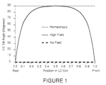
- Figure 1 is a plot of the tilt angle of a liquid crystal molecule as a function of position in a liquid crystal cell for various conditions.
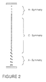
- Figure 2 is a schematic diagram illustrating the liquid crystal director orientations across a liquid crystal cell gap with a strong field applied.
- Figure 3 is a graphical plot showing the transmission of light versus applied voltage for a typical normally white twisted nematic cell viewed at a large angle.
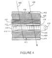
- Figure 4 is a cross sectional schematic side view of a twisted nematic, transmissive type liquid crystal display.
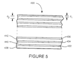
- Figure 5 is an enlarged view of the multilayer portion of the display depicted in Figure 4.
- liquid crystal cells are in widespread use in flat panel displays. Active matrix addressing allows such displays to present a full color image with high resolution at reasonable refresh rates. When viewed directly a liquid crystal display provides high quality output, but the image degrades and exhibits poor contrast at large viewing angles. This occurs because liquid crystal cells operate by virtue of the birefringent effect exhibited by a liquid crystal medium which includes a large number of anisotropic liquid crystal molecules.
- a material will be positively uniaxially birefringent (n e > n o , i.e., the extraordinary refractive index n e is larger than the ordinary refractive index n o ) with an extraordinary refractive index associated with the alignment of the long molecular axes.
- phase retardation effect such a material has on light passing through it inherently varies with the inclination angle of the light, leading to a lower quality image at large viewing angles (See, e.g., Penz, Viewing Characteristics of the Twisted Nematic Display, Proceeding of the S.I.D, Volume 19, Page 43 (1978); Grinberg, et al., Transmission Characteristics of a Twisted Nematic Liquid-Crystal Layer, Journal of the Optical Society of America, Volume 66, Page 1003 (1976)).
- an optical compensating element in conjunction with the liquid crystal cell, however, it is possible to correct for the unwanted angular effects and thereby maintain higher contrast at larger viewing angles than otherwise possible.
- the type of optical compensation required depends upon the type of display, normally black or normally white, which is used.
- a normally black display the twisted nematic cell is placed between polarizers whose transmission axes are parallel to one another and to the orientation of the director of the liquid crystal at the rear of the cell (i.e., the side of the cell away from the viewer).
- the unenergized state no applied voltage
- normally incident light from the backlight is polarized by the first polarizer and in passing through the cell has its polarization direction rotated by the twist angle of the cell. This is caused by adiabatic following, which is also known as the waveguiding effect.
- the twist angle is set to 90° so that the light is blocked by the output polarizer.
- the liquid crystal molecules When a voltage is applied across the cell, the liquid crystal molecules are forced to more nearly align with the electric field, eliminating the twisted nematic symmetry. In this orientation, the optical (c-axis) of the cell is perpendicular to the cell walls. The liquid crystal layer then appears isotropic to normally incident light, eliminating the waveguiding effect so that the polarization state is unchanged by propagation through the liquid crystal layer and such light can pass through the output polarizer. Patterns can be written in the display by selectively applying a voltage to the portions of the display which are to appear illuminated.
- the 90° twisted nematic cell is placed between polarizers which are crossed, such that the transmission axis of each polarizer is parallel to the director orientation of the liquid crystal molecules in the region of the cell adjacent to it. This reverses the sense of light and dark from that of the normally black display.
- the unenergized (no applied voltage) areas appear light in a normally white display, while those which are energized appear dark.
- the problem of ostensibly dark areas appearing light when viewed at large angles still occurs, but the reason for it is different and its correction requires a different type of optical compensating element. In the energized areas the liquid crystal molecules tend to align with the applied electric field.
- Figure 1 is a plot of tilt angle as a function of position in a twisted nematic liquid crystal cell, illustrating a typical distribution of molecular tilt angles throughout the liquid crystal layer under no applied field (represented by the heavy dashed line), high field (represented by the solid line) and ideal homeotropic (represented by the short dashed line) conditions.
- the tilt angle is the angle between the long molecular axis (director) and the plane of the substrate glass. Note that a large fraction of the molecules are nearly homeotropically aligned in the high field condition.
- Figure 2 is a schematic of the liquid crystal director orientations across the cell gap with a strong field applied.
- the continuous variation can be analytically divided into three liquid crystal regions, each characterized by its own optical symmetry. Adjacent to each substrate glass is a region whose symmetry is that of an A-plate with its extraordinary axis aligned with the substrate rub direction. Between them is the larger region which exhibits positive C-plate symmetry.
- the negative C-plate compensator is designed to correct for the angle dependent phase shift introduced by propagation through this region. It is effective to the extent that the optical symmetry of this region dominates the selected state of the liquid crystal cell, that is, the extent to which the molecules align with the applied field. This implies that it will work when strong fields are used for the select state as this makes the homeotropic approximation more nearly correct.
- Uncompensated full color liquid crystal displays typically exhibit a large variation in chromaticity over the field of view. Consequently, an area which appears one color when viewed at normal incidence may appear less saturated or may even appear as its complementary color when viewed at large angles. This results from the same physical mechanism which causes diminished contrast at large angles, i.e., unwanted light leakage through the ostensibly dark areas.
- a full color display is achieved by placing red, blue, and green transmissive filters on a display's pixels.
- a red area is presented by selecting (applying voltage to) the blue and green pixels in that area to make them nontransmissive, while leaving the red pixels nonselected.
- This scheme functions adequately when viewed directly, but at large angles the blue and green pixels begin to transmit, thereby causing the red to appear washed out. This effect is suppressed in the normally white display by a C-plate compensator. Desaturation is eliminated by suppressing dark state leakage.
- Figure 3 is a graphical plot showing transmission of light versus applied voltage for a typical normally white twisted nematic cell viewed at a large angle.
- This example depicts data obtained for a viewing angle of 40° off normal in the horizontal plane and 8° off of normal incidence in the vertical plane.
- the transmission curves are shown for both uncompensated (solid line) and C-plate compensated (dashed line) displays.
- the compensated display the transmission decreases monotonically with voltage, whereas in the uncompensated display the trend reverses so that the transmission at high voltage can exceed that at intermediate voltages. This is particularly troublesome when the display is operated in gray scale mode, which is a technique for displaying low luminance levels by using intermediate voltages to drive the bright areas.
- layered media which consist of alternating thin films of materials with different indices of refraction.
- Such a layered structure can operate as an artificially birefringent thin plate.
- a multilayer compensator fabricated in this manner can be made to exhibit negative birefringence; moreover, the desired birefringence of the multilayer structure can be tailored precisely by choosing proper layer thicknesses and materials.
- This thin film structure provides a powerful technique for effectively compensating the undesirable phase retardation of the homeotropically aligned state in a liquid crystal display.
- ⁇ 1 2 2 ⁇ ⁇ (n eL - n oL )d L
- n eL and n oL are the refractive indices of the homeotropically aligned liquid crystal
- d L is the thickness of the liquid crystal cell
- ⁇ is the wavelength of the transmitted light (note that n eL varies as a function of viewing angle).
- phase retardation would equal ⁇ for a wavelength ⁇ of 0.6 ⁇ m. Phase retardation values of this magnitude can cause a severe leakage of light from the liquid crystal at such oblique viewing angles.
- equations 2) and 3) provide approximations which apply only to wavelengths away from the major reflection bands of the ⁇ /4 structure for the transmitted light, since these expressions do not account for dispersion from the quarter wave band. It can be shown that the birefringence of such a periodic structure, with periods much smaller than a wavelength, is always negative (i.e., n o > n e ). By choosing layer materials having the appropriate indices of refraction and thicknesses, both n o and n e for the composite multilayer can be precisely tailored.
- n oL and n eL are the ordinary and extraordinary refractive indices of the homeotropically aligned liquid crystal, then for optimum compensation layer materials should be selected such that the product of the birefringence of the liquid crystal layer and its thickness is equal and opposite to the product of the birefringence of the multilayer compensator and its thickness.
- the thickness of the C-compensator should equal the thickness of the liquid crystal layer.
- FIG. 4 is a cross sectional schematic side view of a twisted nematic, transmissive type normally white liquid crystal display (LCD) constructed according to this invention.
- the display includes a polarizer layer 402 and an analyzer layer 404, between which is positioned a liquid crystal layer 406, consisting of a liquid crystal material in the nematic phase.
- the polarizer and the analyzer as is indicated by the symbols 408 (representing a polarization direction in the plane of the drawing) and 410 (representing a polarization direction orthogonal to the plane of the drawing), are oriented with their polarization directions at 90° to one another, as is the case for a normally white display.
- a first transparent electrode 412 and a second transparent electrode 414 are positioned adjacent to opposite surfaces of the liquid crystal layer so that a voltage can be applied, by means of a voltage source 416, across the liquid crystal layer.
- the liquid crystal layer is in addition sandwiched between a pair of glass plates 418 and 420.
- the inner surfaces of the glass plates 418 and 420, which are proximate to the liquid crystal layer 406, are physically treated, as by buffing.
- Substrates 422 and 424 provide support structure for the aforementioned layers of the display.
- the director will twist smoothly through an angle of 90° along a path in the layer 406 from the first major surface adjacent to the plate 418 to the second major surface adjacent to the plate 420. Consequently, in the absence of an applied electric field the direction of polarization of incoming polarized light will be rotated by 90° in travelling through the liquid crystal layer.
- crossed polarizers such as the polarizer 408 and the analyzer 410
- light polarized by the polarizer 408 and traversing the display as exemplified by the light ray 426, will thus be aligned with the polarization direction of the analyzer 410 and therefore will pass through the analyzer.
- the compensator includes a first series of layers having a first refractive index which alternate with a second series of layers having a second refractive index.
- the values of the first and second refractive indices, as well as the thicknesses of the layers in the first and the second series, are chosen such that the phase retardation of the multilayer is equal in magnitude but opposite in sign to the phase retardation of the liquid crystal layer.
- An enlarged view of the multilayer 430 is depicted in a cross sectional side view in Figure 5.
- This view shows a first series 432, 434, 436... of layers having a first thickness d 1 and a second series 438, 440, 442... of layers having a second thickness d 2 .
- the thicknesses of the layers are exaggerated relative to the dimensions of an actual multilayer and the number of layers depicted is lower than would typically be employed in an actual multilayer, as indicated by the dashed lines in the middle of the multilayer.
- the preferred embodiment illustrated here includes a multilayer compensator having two series of alternating layers comprising a first and a second optical material
- a multilayer compensator having two series of alternating layers comprising a first and a second optical material
- the concept of a multilayer compensator applies as well to more complex multilayers including periodic layer structures of three or more materials, as well as multilayers in which the different layers of a particular material vary in thickness.
- the inventive concept is applicable to reflective as well as transmissive type liquid crystal displays.
- Another type of liquid crystal display which can benefit from this invention is the supertwist nematic cell, which exhibits voltage response characteristics allowing it to be addressed by simple multiplexing, thereby avoiding the expense and manufacturing difficulty associated with active matrix addressing.
- the supertwist configuration is achieved by doping the nematic liquid crystal material with a chiral additive which gives the cell 270° of total twist.
- Supertwist nematic cells are typically used in the normally black configuration, often employing the compensation techniques described above for normally black displays. Such cells, however, can also be operated in the normally white mode and such normally white supertwist displays would also benefit from the addition of the multilayer compensator of this invention for field of view enhancement.
- the compensation scheme of this invention is broadly applicable to any liquid crystal display device which employs a homeotropically aligned state as part of its operation.
- Other types of liquid crystal displays such as, for example, ferroelectric, can be improved with this invention by acquiring a wider field of view in the aligned state which exhibits C-axis symmetry.
Landscapes
- Physics & Mathematics (AREA)
- Nonlinear Science (AREA)
- Mathematical Physics (AREA)
- Chemical & Material Sciences (AREA)
- Crystallography & Structural Chemistry (AREA)
- General Physics & Mathematics (AREA)
- Optics & Photonics (AREA)
- Liquid Crystal (AREA)
Applications Claiming Priority (2)
| Application Number | Priority Date | Filing Date | Title |
|---|---|---|---|
| US07/786,621 US5196953A (en) | 1991-11-01 | 1991-11-01 | Compensator for liquid crystal display, having two types of layers with different refractive indices alternating |
| US786621 | 1991-11-01 |
Publications (2)
| Publication Number | Publication Date |
|---|---|
| EP0539847A1 EP0539847A1 (en) | 1993-05-05 |
| EP0539847B1 true EP0539847B1 (en) | 1996-11-20 |
Family
ID=25139126
Family Applications (1)
| Application Number | Title | Priority Date | Filing Date |
|---|---|---|---|
| EP92117954A Expired - Lifetime EP0539847B1 (en) | 1991-11-01 | 1992-10-20 | Compensator for liquid crystal display |
Country Status (5)
| Country | Link |
|---|---|
| US (1) | US5196953A (OSRAM) |
| EP (1) | EP0539847B1 (OSRAM) |
| JP (1) | JP3162210B2 (OSRAM) |
| DE (1) | DE69215332T2 (OSRAM) |
| TW (1) | TW287243B (OSRAM) |
Families Citing this family (121)
| Publication number | Priority date | Publication date | Assignee | Title |
|---|---|---|---|---|
| JP2916331B2 (ja) * | 1991-11-08 | 1999-07-05 | 株式会社日立製作所 | 液晶表示装置 |
| JP3250853B2 (ja) * | 1992-11-09 | 2002-01-28 | 松下電器産業株式会社 | 液晶表示装置およびそれを用いた投写型表示装置 |
| US5410422A (en) * | 1993-03-03 | 1995-04-25 | Tektronix, Inc. | Gray scale liquid crystal display having a wide viewing angle |
| US5580950A (en) * | 1993-04-21 | 1996-12-03 | The University Of Akron | Negative birefringent rigid rod polymer films |
| WO1994024191A1 (en) | 1993-04-21 | 1994-10-27 | The University Of Akron | Negative birefringent polyimide films |
| US5344916A (en) * | 1993-04-21 | 1994-09-06 | The University Of Akron | Negative birefringent polyimide films |
| JP3401049B2 (ja) * | 1993-05-26 | 2003-04-28 | コーニンクレッカ フィリップス エレクトロニクス エヌ ヴィ | 階調液晶表示パネル |
| US5499126A (en) | 1993-12-02 | 1996-03-12 | Ois Optical Imaging Systems, Inc. | Liquid crystal display with patterned retardation films |
| US5907378A (en) * | 1993-12-15 | 1999-05-25 | Ois Optical Imaging Systems, Inc. | Normally white twisted nematic liquid crystal display including retardation films for improving viewing characteristics |
| US5594568A (en) * | 1993-12-15 | 1997-01-14 | Ois Optical Imaging Systems, Inc. | LCD with a pair of retardation films on one side of normally white liquid crystal layer |
| US5570214A (en) * | 1993-12-15 | 1996-10-29 | Ois Optical Imaging Systems, Inc. | Normally white twisted nematic LCD with retardation films on opposite sides of liquid crystal material for improved viewing zone |
| US5576861A (en) | 1993-12-15 | 1996-11-19 | Ois Optical Imaging Systems, Inc. | Liquid crystal display having a retarder with 100-200nm retardation and having high contrast viewing zone centered in positive or negative vertical region |
| US5657140A (en) | 1993-12-15 | 1997-08-12 | Ois Optical Imaging Systems, Inc. | Normally white twisted nematic LCD with positive and negative retarders |
| US5619352A (en) * | 1994-04-04 | 1997-04-08 | Rockwell International Corporation | LCD splay/twist compensator having varying tilt and /or azimuthal angles for improved gray scale performance |
| US5504603A (en) | 1994-04-04 | 1996-04-02 | Rockwell International Corporation | Optical compensator for improved gray scale performance in liquid crystal display |
| US5986734A (en) | 1994-04-04 | 1999-11-16 | Rockwell International Corporation | Organic polymer O-plate compensator for improved gray scale performance in twisted nematic liquid crystal displays |
| US5612801A (en) * | 1994-04-04 | 1997-03-18 | Rockwell Science Center, Inc. | Monolithic optical compensation device for improved viewing angle in liquid crystal displays |
| US5638197A (en) * | 1994-04-04 | 1997-06-10 | Rockwell International Corp. | Inorganic thin film compensator for improved gray scale performance in twisted nematic liquid crystal displays and method of making |
| US5745200A (en) * | 1994-04-28 | 1998-04-28 | Casio Computer Co., Ltd. | Color liquid crystal display device and liquid crystal display apparatus |
| WO1995033223A1 (en) * | 1994-05-27 | 1995-12-07 | The University Of Akron | Non-birefringent optical adhesives and films |
| US5557434A (en) * | 1994-09-30 | 1996-09-17 | Rockwell International | Optical compensator including an o-plate for super-twist nematic liquid crystal display |
| US5638200A (en) * | 1995-02-03 | 1997-06-10 | Ois Optical Imaging Systems, Inc. | Liquid crystal display with tilted retardation film |
| US5777706A (en) * | 1996-05-17 | 1998-07-07 | Motorola, Inc. | Nematic liquid crystal phase spatial light modulator for enhanced display resolution |
| US5750641A (en) * | 1996-05-23 | 1998-05-12 | Minnesota Mining And Manufacturing Company | Polyimide angularity enhancement layer |
| US5761060A (en) * | 1996-06-25 | 1998-06-02 | University Of Utah | System and method for evaluating sign legibility |
| JPH1073823A (ja) * | 1996-09-02 | 1998-03-17 | Hitachi Ltd | アクティブマトリクス型液晶表示装置 |
| US6642981B1 (en) | 1996-09-30 | 2003-11-04 | Fujitsu Display Technologies Corporation | Liquid crystal display device operating in a vertically aligned mode including at least one retardation film |
| FR2754609B1 (fr) * | 1996-10-15 | 1998-12-18 | Sextant Avionique | Panneau de visualisation avec compensation par films birefringents holographiques |
| GB2321529A (en) * | 1997-01-24 | 1998-07-29 | Sharp Kk | Broadband cholesteric optical device |
| US5926241A (en) * | 1997-02-24 | 1999-07-20 | Rockwell International Corporation | Photo-patterned compensator with thin film having optically birefringent and isotropic regions and method of manufacturing for a liquid crystal display |
| US6980267B1 (en) * | 1997-05-09 | 2005-12-27 | Lg.Philips Lcd Co., Ltd. | Reflective-type liquid crystal display device having two uniaxial compensation films of same type and method for making the same |
| US5982465A (en) * | 1997-07-11 | 1999-11-09 | Rockwell International Corporation | Film compensated normally white super-twist nematic liquid crystal display that reduces chromaticity shifts over large temperature and viewing angle range |
| EP0895115B1 (en) * | 1997-07-29 | 2005-02-16 | Victor Company Of Japan, Ltd. | Liquid crystal displaying apparatus |
| EP2098906A1 (en) * | 1997-08-29 | 2009-09-09 | Sharp Kabushiki Kaisha | Liquid crystal display device |
| JP3204182B2 (ja) * | 1997-10-24 | 2001-09-04 | 日本電気株式会社 | 横電界方式の液晶表示装置 |
| US6211934B1 (en) | 1997-12-24 | 2001-04-03 | Honeywell Inc. | Method of and apparatuses for reducing infrared loading on display devices |
| US6384889B1 (en) * | 1998-07-24 | 2002-05-07 | Sharp Kabushiki Kaisha | Liquid crystal display with sub pixel regions defined by sub electrode regions |
| US5995184A (en) * | 1998-09-28 | 1999-11-30 | Rockwell Science Center, Llc | Thin film compensators having planar alignment of polymerized liquid crystals at the air interface |
| US6680766B1 (en) | 1998-12-31 | 2004-01-20 | Honeywell Inc. | Liquid crystal display wherein twist angle of liquid crystal material differ from 90° by approximately 15° or more |
| JP2001091741A (ja) * | 1999-09-22 | 2001-04-06 | Fuji Photo Film Co Ltd | 位相差板および円偏光板 |
| US6239853B1 (en) | 1999-10-01 | 2001-05-29 | Rockwell Science Center, Llc | Staggered waveplate LCD privacy screen |
| US6590707B1 (en) | 2000-03-31 | 2003-07-08 | 3M Innovative Properties Company | Birefringent reflectors using isotropic materials and form birefringence |
| TW522260B (en) * | 2000-04-03 | 2003-03-01 | Konishiroku Photo Ind | Optical compensation sheet and liquid crystal display |
| DE60120699T2 (de) * | 2000-04-24 | 2006-11-16 | Nitto Denko Corp., Ibaraki | Flüssigkristallanzeige mit o- und e-typ polarisatoren |
| US7015990B2 (en) | 2000-04-24 | 2006-03-21 | Nitto Denko Corporation | Liquid crystal display including O-type and E-type polarizer |
| JP2002182212A (ja) * | 2000-12-11 | 2002-06-26 | Nitto Denko Corp | 光学素子及び液晶表示装置 |
| US6841654B2 (en) | 2001-05-15 | 2005-01-11 | Rockwell Scientific Licensing, Llc | Polymide-free alignment layer for LCD fabrication and method |
| EP1420275B1 (en) * | 2001-08-24 | 2008-10-08 | Asahi Glass Company, Limited | Isolator and optical attenuator |
| US20030090012A1 (en) * | 2001-09-27 | 2003-05-15 | Allen Richard Charles | Methods of making polarization rotators and articles containing the polarization rotators |
| US6985291B2 (en) * | 2001-10-01 | 2006-01-10 | 3M Innovative Properties Company | Non-inverting transflective assembly |
| US7061561B2 (en) * | 2002-01-07 | 2006-06-13 | Moxtek, Inc. | System for creating a patterned polarization compensator |
| US6909473B2 (en) * | 2002-01-07 | 2005-06-21 | Eastman Kodak Company | Display apparatus and method |
| US6839103B2 (en) * | 2002-02-28 | 2005-01-04 | Kent State University | Elliptically polarizing plate and liquid crystal display |
| US6919946B2 (en) * | 2002-04-16 | 2005-07-19 | 3M Innovative Properties Company | Compensators for liquid crystal displays and the use and manufacture of the compensators |
| JP2004004150A (ja) * | 2002-05-13 | 2004-01-08 | Sumitomo Chem Co Ltd | 積層位相差フィルム及びそれを用いた液晶表示装置 |
| US7554635B2 (en) * | 2002-07-19 | 2009-06-30 | Fujifilm Corporation | Liquid crystal projector, liquid crystal device and substrate for liquid crystal device |
| US6958864B2 (en) | 2002-08-22 | 2005-10-25 | Asml Netherlands B.V. | Structures and methods for reducing polarization aberration in integrated circuit fabrication systems |
| GB2393262B (en) * | 2002-09-20 | 2006-03-29 | Merck Patent Gmbh | New mode lcd comprising two O plate retardation films |
| US7327432B2 (en) * | 2002-11-02 | 2008-02-05 | Merck Patent Gesellschaft Mit Beschrankter Haftung | Optically compensated electro-optical light modulation element with optically isotropic phase |
| CN100367050C (zh) * | 2002-12-24 | 2008-02-06 | 住友化学工业株式会社 | 光学补偿板及使用光学补偿板的投射型液晶显示装置 |
| JP2004212468A (ja) * | 2002-12-27 | 2004-07-29 | Fuji Photo Film Co Ltd | 位相差補償素子及び単板式カラー液晶プロジェクタ |
| JP2004294982A (ja) * | 2003-03-28 | 2004-10-21 | Sumitomo Chem Co Ltd | 位相差板一体型偏光フィルム及びそれを用いた液晶表示装置 |
| SI21526A (sl) * | 2003-05-16 | 2004-12-31 | Institut "Jožef Stefan" | Visoko kontrastni tekočekristalni svetlobno preklopni element s širokim vidnim kotom |
| WO2004104680A1 (en) * | 2003-05-22 | 2004-12-02 | Koninklijke Philips Electronics N.V. | Liquid crystal display device having form birefringent compensator |
| US7170574B2 (en) * | 2003-12-11 | 2007-01-30 | Jds Uniphase Corporation | Trim retarders incorporating negative birefringence |
| US8164721B2 (en) * | 2003-12-11 | 2012-04-24 | Tan Kim L | Grating trim retarders |
| KR101073328B1 (ko) * | 2003-12-16 | 2011-10-12 | 엘지디스플레이 주식회사 | 보상필름을 이용한 액정표시장치 및 그 제조방법 |
| JP2005292781A (ja) * | 2004-03-11 | 2005-10-20 | Fuji Photo Film Co Ltd | 光学補償素子、光学補償素子の製造方法、液晶表示装置及び液晶プロジェクタ |
| US20050275944A1 (en) * | 2004-06-11 | 2005-12-15 | Wang Jian J | Optical films and methods of making the same |
| US7670758B2 (en) * | 2004-04-15 | 2010-03-02 | Api Nanofabrication And Research Corporation | Optical films and methods of making the same |
| JP2005309290A (ja) * | 2004-04-26 | 2005-11-04 | Sumitomo Chemical Co Ltd | 複合偏光板、その製造方法及び液晶表示装置 |
| JP2005338215A (ja) * | 2004-05-25 | 2005-12-08 | Sumitomo Chemical Co Ltd | 複合位相差板及び複合光学部材の製造方法 |
| US20060001969A1 (en) * | 2004-07-02 | 2006-01-05 | Nanoopto Corporation | Gratings, related optical devices and systems, and methods of making such gratings |
| CN100517007C (zh) * | 2004-10-15 | 2009-07-22 | 奇美电子股份有限公司 | 具有光学补偿件的液晶显示器 |
| JP2006119444A (ja) * | 2004-10-22 | 2006-05-11 | Fuji Photo Film Co Ltd | 位相差補償素子およびそれを用いた液晶装置 |
| US7800823B2 (en) * | 2004-12-06 | 2010-09-21 | Moxtek, Inc. | Polarization device to polarize and further control light |
| US7630133B2 (en) * | 2004-12-06 | 2009-12-08 | Moxtek, Inc. | Inorganic, dielectric, grid polarizer and non-zero order diffraction grating |
| US7570424B2 (en) * | 2004-12-06 | 2009-08-04 | Moxtek, Inc. | Multilayer wire-grid polarizer |
| US20080055549A1 (en) * | 2006-08-31 | 2008-03-06 | Perkins Raymond T | Projection Display with an Inorganic, Dielectric Grid Polarizer |
| US20080055720A1 (en) * | 2006-08-31 | 2008-03-06 | Perkins Raymond T | Optical Data Storage System with an Inorganic, Dielectric Grid Polarizer |
| US20080055722A1 (en) * | 2006-08-31 | 2008-03-06 | Perkins Raymond T | Optical Polarization Beam Combiner/Splitter with an Inorganic, Dielectric Grid Polarizer |
| US7961393B2 (en) * | 2004-12-06 | 2011-06-14 | Moxtek, Inc. | Selectively absorptive wire-grid polarizer |
| US20080055721A1 (en) * | 2006-08-31 | 2008-03-06 | Perkins Raymond T | Light Recycling System with an Inorganic, Dielectric Grid Polarizer |
| US7619816B2 (en) * | 2004-12-15 | 2009-11-17 | Api Nanofabrication And Research Corp. | Structures for polarization and beam control |
| US20060127830A1 (en) * | 2004-12-15 | 2006-06-15 | Xuegong Deng | Structures for polarization and beam control |
| EP1825305A4 (en) * | 2004-12-15 | 2010-07-07 | Fujifilm Corp | DEPHASING COMPENSATOR, LIGHT MODULATION SYSTEM, LIQUID CRYSTAL DISPLAY, AND LIQUID CRYSTAL PROJECTOR |
| US8237876B2 (en) * | 2005-05-25 | 2012-08-07 | Kim Leong Tan | Tilted C-plate retarder compensator and display systems incorporating the same |
| EP1899752B1 (en) * | 2005-07-05 | 2014-08-27 | FUJIFILM Corporation | Retardation compensation element, liquid crystal display device, and liquid crystal projector |
| US7714945B2 (en) * | 2005-09-09 | 2010-05-11 | Jds Uniphase Corporation | Optimally clocked trim retarders |
| US7515231B2 (en) * | 2005-09-30 | 2009-04-07 | Teledyne Scientific & Imaging, Llc | Low temperature nematic liquid crystal alignment material and LCD compensator incorporating the liquid crystal alignment material |
| US7671945B2 (en) * | 2005-09-30 | 2010-03-02 | Teledyne Scientific & Imaging, Llc | UV curable alignment material for fabrication of monolithic compensators for liquid crystal displays |
| US7671946B2 (en) * | 2005-10-18 | 2010-03-02 | Jds Uniphase Corporation | Electronically compensated LCD assembly |
| US20070139771A1 (en) * | 2005-12-15 | 2007-06-21 | Jian Wang | Optical retarders and methods of making the same |
| US20070165308A1 (en) * | 2005-12-15 | 2007-07-19 | Jian Wang | Optical retarders and methods of making the same |
| US20070217008A1 (en) * | 2006-03-17 | 2007-09-20 | Wang Jian J | Polarizer films and methods of making the same |
| US7848020B2 (en) * | 2006-06-02 | 2010-12-07 | Jds Uniphase Corporation | Thin-film design for positive and/or negative C-plate |
| US20070296921A1 (en) * | 2006-06-26 | 2007-12-27 | Bin Wang | Projection display with a cube wire-grid polarizing beam splitter |
| US20070297052A1 (en) * | 2006-06-26 | 2007-12-27 | Bin Wang | Cube wire-grid polarizing beam splitter |
| EP1892706B1 (en) | 2006-08-23 | 2012-06-13 | JDS Uniphase Corporation | Optical pick-up unit |
| US8755113B2 (en) * | 2006-08-31 | 2014-06-17 | Moxtek, Inc. | Durable, inorganic, absorptive, ultra-violet, grid polarizer |
| US7898603B2 (en) * | 2006-11-30 | 2011-03-01 | Reald Inc. | Double-shutter lenses with compensators |
| TWI427374B (zh) * | 2006-12-27 | 2014-02-21 | Fujifilm Corp | 遲延度補償元件、垂直配向向列型液晶顯示裝置、及液晶投影機 |
| EP3133438A1 (en) | 2007-02-09 | 2017-02-22 | Viavi Solutions Inc. | Single-layer birefringent crystal optical retarders |
| EP1980902B1 (en) * | 2007-04-10 | 2015-07-15 | JDS Uniphase Corporation | Twisted nematic xLCD contrast compensation with tilted-plate retarders |
| US7789515B2 (en) * | 2007-05-17 | 2010-09-07 | Moxtek, Inc. | Projection device with a folded optical path and wire-grid polarizer |
| WO2008146924A1 (ja) * | 2007-06-01 | 2008-12-04 | Teijin Limited | 位相差フィルム、積層偏光フィルム、および液晶表示装置 |
| US20080316599A1 (en) * | 2007-06-22 | 2008-12-25 | Bin Wang | Reflection-Repressed Wire-Grid Polarizer |
| JP2009075459A (ja) * | 2007-09-21 | 2009-04-09 | Fujifilm Corp | 二軸性複屈折体の製造方法、二軸性複屈折体及び液晶プロジェクタ |
| JP4450043B2 (ja) * | 2007-09-28 | 2010-04-14 | ソニー株式会社 | 投射型液晶表示装置 |
| JP2009181689A (ja) * | 2008-01-30 | 2009-08-13 | Jds Uniphase Corp | 2ミラー位相シフタを有する光ピックアップ・ユニット |
| JP5228559B2 (ja) | 2008-03-25 | 2013-07-03 | ソニー株式会社 | 画像表示装置および光学補償装置 |
| US20100103517A1 (en) * | 2008-10-29 | 2010-04-29 | Mark Alan Davis | Segmented film deposition |
| US8248696B2 (en) | 2009-06-25 | 2012-08-21 | Moxtek, Inc. | Nano fractal diffuser |
| US8611007B2 (en) | 2010-09-21 | 2013-12-17 | Moxtek, Inc. | Fine pitch wire grid polarizer |
| US8913321B2 (en) | 2010-09-21 | 2014-12-16 | Moxtek, Inc. | Fine pitch grid polarizer |
| US8913320B2 (en) | 2011-05-17 | 2014-12-16 | Moxtek, Inc. | Wire grid polarizer with bordered sections |
| US8873144B2 (en) | 2011-05-17 | 2014-10-28 | Moxtek, Inc. | Wire grid polarizer with multiple functionality sections |
| US8922890B2 (en) | 2012-03-21 | 2014-12-30 | Moxtek, Inc. | Polarizer edge rib modification |
| US9075201B2 (en) * | 2012-10-04 | 2015-07-07 | Tera Xtal Technology Corporation | Polarization conversion mechanism and method thereof |
| US8976306B2 (en) * | 2013-01-09 | 2015-03-10 | Shenzhen China Star Optoelectronics Technology Co., Ltd. | Shutter glasses and related 3D display system |
| US9348076B2 (en) | 2013-10-24 | 2016-05-24 | Moxtek, Inc. | Polarizer with variable inter-wire distance |
Family Cites Families (18)
| Publication number | Priority date | Publication date | Assignee | Title |
|---|---|---|---|---|
| US4385806A (en) * | 1978-06-08 | 1983-05-31 | Fergason James L | Liquid crystal display with improved angle of view and response times |
| JPS5887538A (ja) * | 1981-11-20 | 1983-05-25 | Hitachi Ltd | 液晶表示素子 |
| FR2564605B1 (fr) * | 1984-05-18 | 1987-12-24 | Commissariat Energie Atomique | Cellule a cristal liquide susceptible de presenter une structure homeotrope, a birefringence compensee pour cette structure |
| JPS6231822A (ja) * | 1985-08-02 | 1987-02-10 | Hitachi Ltd | 液晶表示素子 |
| FR2595156B1 (fr) * | 1986-02-28 | 1988-04-29 | Commissariat Energie Atomique | Cellule a cristal liquide utilisant l'effet de birefringence controlee electriquement et procedes de fabrication de la cellule et d'un milieu uniaxe d'anisotropie optique negative, utilisable dans celle-ci |
| DE3752339T2 (de) * | 1986-05-19 | 2002-05-08 | Seiko Epson Corp., Tokio/Tokyo | Flüssigkristallanzeigevorrichtung |
| EP0312297B1 (en) * | 1987-10-13 | 1994-01-26 | Fujitsu Limited | Liquid crystal display panel |
| JPH01120527A (ja) * | 1987-11-04 | 1989-05-12 | Sharp Corp | 液晶表示装置 |
| US4936654A (en) * | 1988-01-28 | 1990-06-26 | Sanyo Electric Co., Ltd. | Liquid crystal display device |
| JPH0769538B2 (ja) * | 1988-07-04 | 1995-07-31 | スタンレー電気株式会社 | 補償したねじれネマチック液晶表示装置 |
| EP0350063A3 (en) * | 1988-07-08 | 1990-09-05 | Kabushiki Kaisha Toshiba | Liquid crystal display device |
| JP2856401B2 (ja) * | 1988-07-08 | 1999-02-10 | 株式会社東芝 | 液晶表示素子 |
| DE68923929T2 (de) * | 1988-11-04 | 1996-03-07 | Fuji Photo Film Co Ltd | Flüssigkristall-Anzeige. |
| JP2675158B2 (ja) * | 1988-12-07 | 1997-11-12 | シャープ株式会社 | 液晶表示装置 |
| JP3071204B2 (ja) * | 1989-02-10 | 2000-07-31 | 株式会社リコー | 液晶表示素子 |
| US4984872A (en) * | 1989-06-16 | 1991-01-15 | Rockwell International Corporation | Wide viewing angle avionics liquid crystal display |
| US5126866A (en) * | 1989-08-11 | 1992-06-30 | Sharp Kabushiki Kaisha | Liquid crystal display with a plurality of phase difference plates the slow axes of which form an angle of 20 to 40 degrees |
| JPH03263013A (ja) * | 1990-03-14 | 1991-11-22 | Fujitsu Ltd | 液晶パネル |
-
1991
- 1991-11-01 US US07/786,621 patent/US5196953A/en not_active Expired - Lifetime
-
1992
- 1992-10-20 EP EP92117954A patent/EP0539847B1/en not_active Expired - Lifetime
- 1992-10-20 DE DE69215332T patent/DE69215332T2/de not_active Expired - Lifetime
- 1992-10-30 JP JP29333992A patent/JP3162210B2/ja not_active Expired - Lifetime
-
1993
- 1993-02-10 TW TW082100932A patent/TW287243B/zh not_active IP Right Cessation
Non-Patent Citations (1)
| Title |
|---|
| PATENT ABSTRACTS OF JAPAN vol. 10, no. 260 (P-494)5 September 1986 JP-A-61 087 101 (NIPPON TELEGRAPH & TELEPHONE) 2 May 1986 & DATABASE WPIL Week 8624, Derwent Publications Ltd., London, GB;AN 86_153143 * |
Also Published As
| Publication number | Publication date |
|---|---|
| TW287243B (OSRAM) | 1996-10-01 |
| DE69215332T2 (de) | 1997-03-20 |
| EP0539847A1 (en) | 1993-05-05 |
| JPH05249457A (ja) | 1993-09-28 |
| JP3162210B2 (ja) | 2001-04-25 |
| US5196953A (en) | 1993-03-23 |
| DE69215332D1 (de) | 1997-01-02 |
Similar Documents
| Publication | Publication Date | Title |
|---|---|---|
| EP0539847B1 (en) | Compensator for liquid crystal display | |
| US5986733A (en) | Negative optical compensator tilted in respect to liquid crystal cell for liquid crystal display | |
| JP3321559B2 (ja) | 液晶表示装置 | |
| EP0821261B1 (en) | Reflective type liquid crystal display device | |
| US5124824A (en) | Liquid crystal display device comprising a retardation compensation layer having a maximum principal refractive index in the thickness direction | |
| US6341002B1 (en) | Liquid crystal display device | |
| EP0676660B1 (en) | Optical compensator for improved gray scale performance in liquid crystal display | |
| JP3410666B2 (ja) | 液晶表示装置 | |
| US5568287A (en) | Liquid crystal device with optical means of high refractive index at pixels and low refractive index between pixels | |
| US5541753A (en) | Liquid crystal display and device having a total retardance of (M+1) λ/2 and (Mλ/2) at first and second operating voltages | |
| US6937308B2 (en) | In-plane switching liquid crystal display with compensation film | |
| US5570211A (en) | Color liquid crystal display device using birefringence | |
| US4904058A (en) | Liquid crystal display panel | |
| JP2000029010A (ja) | 液晶表示装置 | |
| KR20010051811A (ko) | 디스플레이 디바이스 | |
| US5982465A (en) | Film compensated normally white super-twist nematic liquid crystal display that reduces chromaticity shifts over large temperature and viewing angle range | |
| CN1035790C (zh) | 液晶显示补偿器 | |
| KR100202781B1 (ko) | 액정 디스플레이용 보상기 | |
| EP0371797A2 (en) | Liquid crystal display device | |
| JP3896135B2 (ja) | 液晶表示素子および光学異方素子 | |
| JP2003161944A (ja) | 液晶表示装置 | |
| JP2891227B2 (ja) | 液晶装置 | |
| JPH1152348A (ja) | 液晶表示素子 | |
| JP2003161945A (ja) | 液晶表示装置 | |
| JPH10133164A (ja) | 光学フィルム及び液晶表示装置 |
Legal Events
| Date | Code | Title | Description |
|---|---|---|---|
| PUAI | Public reference made under article 153(3) epc to a published international application that has entered the european phase |
Free format text: ORIGINAL CODE: 0009012 |
|
| AK | Designated contracting states |
Kind code of ref document: A1 Designated state(s): AT BE CH DE DK ES FR GB GR IE IT LI LU MC NL PT SE |
|
| RBV | Designated contracting states (corrected) |
Designated state(s): DE FR GB NL |
|
| 17P | Request for examination filed |
Effective date: 19930922 |
|
| 17Q | First examination report despatched |
Effective date: 19950419 |
|
| GRAG | Despatch of communication of intention to grant |
Free format text: ORIGINAL CODE: EPIDOS AGRA |
|
| GRAH | Despatch of communication of intention to grant a patent |
Free format text: ORIGINAL CODE: EPIDOS IGRA |
|
| GRAH | Despatch of communication of intention to grant a patent |
Free format text: ORIGINAL CODE: EPIDOS IGRA |
|
| GRAA | (expected) grant |
Free format text: ORIGINAL CODE: 0009210 |
|
| AK | Designated contracting states |
Kind code of ref document: B1 Designated state(s): DE FR GB NL |
|
| REF | Corresponds to: |
Ref document number: 69215332 Country of ref document: DE Date of ref document: 19970102 |
|
| ET | Fr: translation filed | ||
| PLBE | No opposition filed within time limit |
Free format text: ORIGINAL CODE: 0009261 |
|
| STAA | Information on the status of an ep patent application or granted ep patent |
Free format text: STATUS: NO OPPOSITION FILED WITHIN TIME LIMIT |
|
| 26N | No opposition filed | ||
| REG | Reference to a national code |
Ref country code: GB Ref legal event code: IF02 |
|
| PGFP | Annual fee paid to national office [announced via postgrant information from national office to epo] |
Ref country code: DE Payment date: 20101027 Year of fee payment: 19 |
|
| PGFP | Annual fee paid to national office [announced via postgrant information from national office to epo] |
Ref country code: GB Payment date: 20101025 Year of fee payment: 19 |
|
| PGFP | Annual fee paid to national office [announced via postgrant information from national office to epo] |
Ref country code: NL Payment date: 20111028 Year of fee payment: 20 Ref country code: FR Payment date: 20111028 Year of fee payment: 20 |
|
| REG | Reference to a national code |
Ref country code: DE Ref legal event code: R071 Ref document number: 69215332 Country of ref document: DE |
|
| REG | Reference to a national code |
Ref country code: DE Ref legal event code: R071 Ref document number: 69215332 Country of ref document: DE |
|
| REG | Reference to a national code |
Ref country code: NL Ref legal event code: V4 Effective date: 20121020 |
|
| REG | Reference to a national code |
Ref country code: GB Ref legal event code: PE20 Expiry date: 20121019 |
|
| PG25 | Lapsed in a contracting state [announced via postgrant information from national office to epo] |
Ref country code: GB Free format text: LAPSE BECAUSE OF EXPIRATION OF PROTECTION Effective date: 20121019 |