EP0539232A2 - Elektrisches Saiteninstrument mit einer Vorrichtung zum Halten der Schwingung einer Saite und einem elektromagnetischen Erzeuger dafür - Google Patents
Elektrisches Saiteninstrument mit einer Vorrichtung zum Halten der Schwingung einer Saite und einem elektromagnetischen Erzeuger dafür Download PDFInfo
- Publication number
- EP0539232A2 EP0539232A2 EP92309757A EP92309757A EP0539232A2 EP 0539232 A2 EP0539232 A2 EP 0539232A2 EP 92309757 A EP92309757 A EP 92309757A EP 92309757 A EP92309757 A EP 92309757A EP 0539232 A2 EP0539232 A2 EP 0539232A2
- Authority
- EP
- European Patent Office
- Prior art keywords
- string
- vibration
- magnetic flux
- sustaining
- electromagnetic driver
- Prior art date
- Legal status (The legal status is an assumption and is not a legal conclusion. Google has not performed a legal analysis and makes no representation as to the accuracy of the status listed.)
- Withdrawn
Links
Images


Classifications
-
- G—PHYSICS
- G10—MUSICAL INSTRUMENTS; ACOUSTICS
- G10H—ELECTROPHONIC MUSICAL INSTRUMENTS; INSTRUMENTS IN WHICH THE TONES ARE GENERATED BY ELECTROMECHANICAL MEANS OR ELECTRONIC GENERATORS, OR IN WHICH THE TONES ARE SYNTHESISED FROM A DATA STORE
- G10H3/00—Instruments in which the tones are generated by electromechanical means
- G10H3/12—Instruments in which the tones are generated by electromechanical means using mechanical resonant generators, e.g. strings or percussive instruments, the tones of which are picked up by electromechanical transducers, the electrical signals being further manipulated or amplified and subsequently converted to sound by a loudspeaker or equivalent instrument
- G10H3/24—Instruments in which the tones are generated by electromechanical means using mechanical resonant generators, e.g. strings or percussive instruments, the tones of which are picked up by electromechanical transducers, the electrical signals being further manipulated or amplified and subsequently converted to sound by a loudspeaker or equivalent instrument incorporating feedback means, e.g. acoustic
- G10H3/26—Instruments in which the tones are generated by electromechanical means using mechanical resonant generators, e.g. strings or percussive instruments, the tones of which are picked up by electromechanical transducers, the electrical signals being further manipulated or amplified and subsequently converted to sound by a loudspeaker or equivalent instrument incorporating feedback means, e.g. acoustic using electric feedback
-
- Y—GENERAL TAGGING OF NEW TECHNOLOGICAL DEVELOPMENTS; GENERAL TAGGING OF CROSS-SECTIONAL TECHNOLOGIES SPANNING OVER SEVERAL SECTIONS OF THE IPC; TECHNICAL SUBJECTS COVERED BY FORMER USPC CROSS-REFERENCE ART COLLECTIONS [XRACs] AND DIGESTS
- Y10—TECHNICAL SUBJECTS COVERED BY FORMER USPC
- Y10S—TECHNICAL SUBJECTS COVERED BY FORMER USPC CROSS-REFERENCE ART COLLECTIONS [XRACs] AND DIGESTS
- Y10S84/00—Music
- Y10S84/10—Feedback
Definitions
- the present invention relates to a stringed instrument, e.g., a guitar or a piano, and more particularly to a stringed instrument having a device that drives the strings thereof to sustain the vibration of the string and an electromagnetic driver for the device.
- a guitar or a piano differs from a violin in that after the string of a guitar or a piano is excited, the magnitude of the vibration of the string will become half within about a half second and die within about 7 seconds. Particularly, for example, in the case of an electric guitar, it seems that the attenuation speed of the vibration of the string is shorter than that of an acoustic guitar because of the electric characteristics of an amplifier.
- an effector which is a device for adding several sound effects, e.g., Delay, Reverb, Compressor, Overdrive, etc., to the sound of the guitar is often used to enable more sustained sound to be heard acoustically.
- An effector using Delay or Reverb adds reverberations to a musical sound, and the sound is produced by recording and playing back the sound on a magnetic tape or by delaying the tone by a spring arrangement.
- BBD Bracket Brigade Device
- An effector using a Compressor increases the amplitude of a music signal sent to by an amplifier in reverse proportion to attenuation characteristics of the vibration of the strings, and an Overdrive amplifies the signal beyond a generally permissible level so as to obtain a long tone. A longer tone can be achieved by using these effectors, although the effectors cannot maintain the tone after the vibration of the string has stopped.
- a style using a loudspeaker feedback is one that produces the sound of a guitar at high volume so as to sustain the vibration of the string on the guitar for a long time without attenuation by way of sympathetic vibration in cooperation with air vibration emitted from the loudspeaker.
- the feedback can maintain the vibration of the string for a long time, but in order to sustain the sound, the player must utilize a skilled and high-grade technique to overcome several limitations, i.e., sound volume, location of the amplifier, length of the strings and musical interval, etc.
- the first problem is that a stringed instrument, e.g., a guitar and a piano, has plural strings and the thickness and tension of every string is different, and so the driving force applied to each of them is also different.
- an electromagnetic driver of a stringed instrument having a device for sustaining the vibration of the string for example an electric guitar, emits a constant driving magnetic energy against every string uniformly so that the first string that has the smallest mass and thickness and relatively large tension cannot be excited, oppositely, the fifth string and the sixth string can be excited easily because of the large mass and thickness and relatively low tension of the string.
- a string other than the first string e.g., the fifth string or the sixth string, experiences sudden self-excitation when providing the first string with increased driving force in order to solve the problem as described above.
- the optimum magnetic energy output for driving the first string provides a relatively excitable string, e.g., a fifth string or a sixth string, with excessive driving energy, and thereby, there is a problem in that a fifth string or a sixth string experiences sudden self-excitation by the excessive driving energy described above although the fifth or sixth string is not used for playing music.
- a musician must always mute the fifth and sixth string while playing the guitar and that is a serious problem for the musician.
- the second problem is the emission efficiency of driving magnetic energy.
- a device for sustaining the vibration of a string on a guitar body as a package, and it is clear that an external effector type guitar is substantially inferior to an internal effector type guitar.
- a power supply unit for a device for sustaining the vibration of a string must be essentially small, e.g., a small dry cell battery, to be mounted inside a guitar body.
- a driving current used to excite a string in such an excitation system is usually about 50 mA, and so the emission efficiency of driving magnetic energy is very important so as to prevent the necessity of frequently changing the dry cell battery.
- a bar type pole piece is generally used to enable the guitar to be played using a method for changing pitch, e.g., bending, in which a string is drawn on a fret parallel with the fret by the finger, and thereby, tension of the string and pitch vary.
- pitch e.g., bending
- a single type pole piece is scarcely used, because magnetic energy emitted from each pole piece corresponding to each string lies in the neighborhood of just above each pole piece so that a cut tone is generated if a string is out of the magnetic energy area while playing using the Bending method.
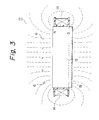
- a bar type pole piece has a flat magnetic flux emitting characteristic and a magnetic field is formed in the up and down direction uniformly.
- circular magnetic fields are formed in the neighborhood of both side ends of a bar type pole piece. Therefore, a magnetic field provided to the strings from a second string to a fifth string is relatively stable and uniform, but a magnetic field provided to a first string and a sixth string is curved as described above so that magnetic field density falls and the driving force for driving a first string and a second string is smaller rather than that for other strings, and excitation balance between strings is lost thereby.
- an excitation balance matching means is provided.
- the excitation balance matching means is a phase control circuit provided in an amplifier and/or means for properly setting up magnetic flux emitted from an electromagnetic driver corresponding to each string.
- a magnetic flux emission controlling means for controlling the relative quantity of magnetic flux emission corresponding to each string.
- the purpose of the present invention is to develop consumption efficiency by providing a driving proper and sufficient magnetic energy to each string, using the excitation balance matching means. Furthermore, the purpose of the present invention is to provide a new designed electromagnetic driver that significantly develops the magnetic energy emitting characteristics.
- a stringed instrument having a device for sustaining the vibration of a string; said stringed instrument being a musical instrument having plural strings with the mass and tension of each string being different, comprises pickup means for detecting the vibration of a string, amplifying means for amplifying an electric signal detected by said pickup means, an electromagnetic driver for emitting magnetic energy to drive a string by a driving signal output from said amplifying means, and excitation balance matching means for providing well-balanced excitation to each of the plural strings and(or magnetic flux emission controlling means for increasing the quantity of magnetic flux emission in the direction of a string.
- the excitation balance matching means is a phase control circuit provided in said amplifying means and the phase control circuit has a fixed phase characteristic and causes each string to be excited by a substantially uniform and well-balanced driving force such that the least excitable string is provided with an optimum condition of the phase characteristic so as to sustain the vibration of the string, and other strings are provided with a progressively mismatched condition so as to suitably weaken the vibration of the strings.
- an electromagnetic driver of a device for sustaining the vibration of a string that is used in a musical instrument having plural strings, the mass and tension of each string being different comprises pickup means for detecting the vibration of a string, amplifying means for amplifying an electric signal detected by said pickup means, an electromagnetic driver for emitting magnetic energy so as to drive a string by an output signal from said amplifying means, and excitation balance matching means for providing well-balanced excitation to each of the plural strings and/or magnetic flux emission controlling means for increasing the quantity of magnetic flux emission in the direction of a string.
- the electromagnetic driver has the arrangement of a coil and plural pole pieces corresponding to plural strings and said excitation balance matching means has a constitution for setting up a magnetic flux emitted from each pole piece properly so as to emit well-suited magnetic flux corresponding to each string respectively, and the electromagnetic driver has an arrangement of a permanent magnet, a coil and a bar type pole piece combined with the permanent magnet magnetically, and the excitation balance matching means and/or the magnetic flux emission controlling means are magnetic flux emission deflecting means formed in the bar type pole piece for deflecting emitted magnetic flux.
- a stringed instrument having a device for sustaining the vibration of a string; the stringed instrument being a musical instrument having plural strings, the mass and tension of each string being different, comprises pickup means for detecting the vibration of a string, amplifying means for amplifying an electric signal detected by the pickup means, and an electromagnetic driver for emitting magnetic energy to drive a string by a driving signal output from the amplifying means, characterized in that the device for sustaining the vibration of a string sustains the vibration of plural strings simultaneously thereby enabling the playing of a chord.
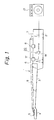
- Fig. 1 is a general schematic arrangement of an electric guitar having a device for sustaining the vibration of strings.
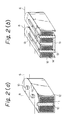
- Fig. 2 (a) and Fig. 2 (b) are cross sectioned views of two types of electromagnetic pickups; one is a so-called single coil type pickup in Fig. 2 (a) and the other is a so-called double coil type pickup in Fig. 2 (b).
- Fig. 3 is a schematic view of a magnetic field emitted from a electromagnetic pickup.
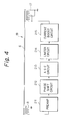
- Fig. 4 is an example of block diagrams of a device for sustaining the vibration of a string.
- Fig. 5 is an example of a phase shift circuit
- Fig. 6 is a schematic view of an example of a device for sustaining the vibration of a string in which plural phase shift circuits are used corresponding to each string.
- Fig. 7 is a schematic view of the first embodiment of the electromagnetic driver according to the present invention.
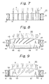
- Fig. 8 is a schematic view of the second embodiment of the electromagnetic driver according to the present invention.
- Fig. 9 is a schematic view of the third embodiment of the electromagnetic driver according to the present invention.
- Fig. 10 is a schematic view of the fourth embodiment of the electromagnetic driver according to the present invention.
- Fig. 11 is a schematic view of the fifth embodiment of the electromagnetic driver according to the present invention.
- Fig. 12 is a schematic view of the sixth (1) embodiment of the electromagnetic driver according to the present invention.
- Fig. 13 is a schematic view of the sixth (2) embodiment of the electromagnetic driver according to the present invention.
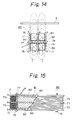
- Fig. 14 is a schematic view of the seventh (1) embodiment of the electromagnetic driver according to the present invention.
- Fig. 15 is a schematic view of the seventh (2) embodiment of the electromagnetic driver according to the present invention.
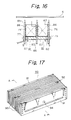
- Fig. 16 is a schematic view of the eighth embodiment of the electromagnetic driver according to the present invention.
- Fig. 17 is a schematic view of the ninth (1) embodiment of the electromagnetic driver according to the present invention.
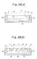
- Fig. 18 (a) and Fig. 18 (b) are schematic views of the ninth (2) embodiment of the electromagnetic driver according to the present invention.
- Fig. 19 is a schematic view of the tenth (1) embodiment of the electromagnetic driver according to the present invention.
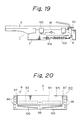
- Fig. 20 is a schematic view of the tenth (2) embodiment of the electromagnetic driver according to the present invention.
- Fig. 21 is a schematic view of the eleventh (1) embodiment of the electromagnetic driver according to the present invention.
- Fig. 22 (a) and Fig. 22 (b) are schematic views of the eleventh (2) embodiment of the electromagnetic driver according to the present invention.
- Fig. 1 shows an electric guitar that has a so-called “sustainer” 20 for sustaining the vibration of a string 6.
- an electric guitar 1 has a body 2 and a neck 3 combined with the body 2.
- Frets 9 are placed side by side on the surface of the neck 3 and a head 4 is shaped at an elongated end portion of the neck 3.
- a plurality of pegs 5 are attached to the head 4 and each peg 5 has a structure for winding up one end of the string 6 made of a metal conductive wire.
- the other end of the string 6 is fixed at a tailpiece attached to the surface of the body 2 or a Tremolo device 7 for producing a Tremolo effect characteristic of an electric guitar by a bar that provides pitch change capability by varying string tension.
- 8 is an electromagnetic pickup. There are typically two types of pickups 8 as shown in Fig. 2 (a) and Fig. 2 (b).
- Fig. 2 (a) is a so-called single coil type pickup that comprises pole pieces 10 made of a magnetic substance, i.e., a permanent magnet, a coil 11 wound around the pole pieces 10 and a cover 12.
- Fig. 2 (b) is a so-called double coil type pickup or a hum-bucking pickup that comprises two pole pieces 13 facing each other and made of magnetic substances, i.e., a ferromagnetic material (Fig. 2 (b) shows an example of a so-called bar type pole-piece.), coils 14 wound up around each pole piece 13 and a permanent magnet 15 combined magnetically with each pole piece 13.
- An induced electromotive force generated at both ends of the coil 11, 14 of the electromagnetic pickup 8 is produced by a variation of magnetic flux penetrating through the inside of the circumference of the coil 11, 14.
- the vibration of the conductive metal string 6 in the magnetic field causes a change in magnetic reluctance in the neighborhood of the electromagnetic pickup 8 and thereby the magnetic flux density inside of the circumference of the coil 11, 14 varies in response to the vibration and an electric signal is produced by the induced electromotive force.
- the sustainer 20 consists fundamentally of the following elements. There are three elements, those are, an electromagnetic pickup 8 for detecting the vibration of the string 6, an amplifier 18 for amplifying an electric signal detected by the electromagnetic pickup 8, and an electromagnetic driver 17 for emitting a driving magnetic energy converted from the electric signal.
- the sustainer 20 as described above operates in the following manner.
- a signal detected at the electromagnetic pickup 8 is applied to an external guitar amplifier 21 and the guitar amplifier 21 outputs a loud sound.
- the signal of the vibration of the string 6 detected at the electromagnetic pickup 8 is also applied to the amplifier 18 within the guitar body 2 and the amplified signal is applied to the electromagnetic driver 17.
- the electromagnetic driver 17 basically uses the inverse of the principle of the electromagnetic pickup 8.
- the electric signal detected at the electromagnetic pickup 8 is amplified by the amplifier 18 and provided to an electromagnetic transducer, i.e., the electromagnetic drive 17.
- the electromagnetic driver 17 has the same structure as the electromagnetic pickup 8 shown in Fig. 2 (a) or Fig. 2 (b) and causes the string 6 to be excited by the emitted magnetic flux.
- the coil portion of the electromagnetic driver 17 is not the same as the electromagnetic pickup 8 because the electromagnetic driver 17 needs a lot of power to obtain significant flux and thereby to drive the string 6. Accordingly the coil of the electromagnetic driver 17 uses a copper wire with a diameter of 0.3 mm larger than that of the electromagnetic pickup 8 and about 200 turns of the wire is wound, therefore the electromagnetic driver 17 has small electric resistance about 7 ohm and low power-loss characteristics.
- a bar type pole piece is generally used to enable the guitar to be played using a method for changing pitch, e.g., bending, in which a string is drawn on a fret parallel with the fret by the finger, and thereby, tension of the string and pitch vary.
- pitch e.g., bending
- a single type pole piece is scarcely used, because magnetic energy emitted from each pole piece corresponding to each string lies in the neighborhood of just above each pole piece so that a cut tone is generated if a string is out of the magnetic energy area while playing using the Bending method.
- a bar type pole piece 13 has a flat magnetic flux emitting characteristic and a magnetic field is formed in the up and down direction uniformly.
- a circular magnetic fields is formed in the neighborhood of both side ends of a bar type pole piece 13. Therefore, a magnetic field provided to strings 6 from a second string to a fifth string is relatively stable and uniform, but a magnetic field provided to a first string and a sixth string is curved as described above so that a magnetic field density falls and so driving force for driving a first string and a second string is smaller rather than that for other strings, and an excitation balance between strings is lost thereby.
- the means has a constitution that suitable adjusting an output phase of magnetic energy to cause the least excitable string, for example a first string, to be driven efficiently and shifts the output phase of magnetic energy intentionally in relation to a fifth string that can be easily excited, and thereby, matches the excitation balance of the plural strings overall.
- Fig. 4 is a block diagram of an embodiment of a device for sustaining the vibration of strings according to the present invention. These circuit elements are mounted on a circuit board located inside a guitar body, except for a string 6, an electromagnetic pickup 8 and an electromagnetic driver 17.
- preamp 211 is a preamplifier for amplifying a micro-vibrational signal of the string 6 detected by the electromagnetic pickup 8, and an output of the preamp 211 is applied to a phase shift circuit 212 at a subsequent stage.
- the phase shift circuit 212 is a phase lead circuit that decreases in quantity of phase shift in proportion to an increase of a frequency of the input signal and has an amplitude characteristic which smoothly damps low frequency signals.
- the phase shift circuit 212 compensates for a phase lag between the electromagnetic pickup 8 and the electromagnetic driver 17, and thereby realizes a predetermined phase shift between the vibration of the string 6 and a driving force for the string 6, and also an effect of sustaining the vibration of the string 6, while maintaining a balance between the vibration of each string by damping low frequency signals and thereby reducing a so-called magnetic feedback to a low frequency string 6, e.g., a fifth string.
- the output of the phase shift circuit 212 is applied to an automatic gain control (AGC) circuit 213.
- AGC automatic gain control
- the AGC circuit 213 keeps the output signal level constant and provides the signal to a subsequent stage.
- the AGC circuit 213 solves the problem that the vibration of the string would be stopped if a quantity of the feed back for sustaining the vibration of the string were too small, and conversely that the vibration of the string would be self-excited if the quantity of the feed back were too large.
- the output of the AGC circuit 213 is applied to a limiter circuit 214.
- the limiter circuit 214 prevents an over range input signal such as an impulse noise from a front stage and also incorporates the function of waveform shaping by limiting a leading edge and/or trailing edge of an input waveform, and thereby prevents an unusual feedback from being induced instantaneously.
- a current boost circuit 215 amplifies a signal from the limiter circuit 214 and provides the amplified signal as a driving current to an electromagnetic driver 17.
- the electromagnetic driver 17 produces a magnetic field to excite the string 6 by the driving current.
- Fig. 5 shows an example of the phase shift circuit 212 as described above.
- an input terminal has applied there to an output signal from the preamp 211 and an output signal from the phase shift circuit 212 is applied to the AGC circuit 213 at a subsequent stage.
- the circuit in Fig. 5 has a high-pass characteristic with a transfer function of
- the phase lead characteristic is matched to an optimum phase point for the maximum excitation of a first string that is the highest frequency string and the least excitable string because of its small mass and thickness, and for the other strings, particularly a fifth and a sixth string which are low frequency strings that can be excited more easily than the first string, it is shifted from the optimum phase point for their excitation. Consequentially, a total excitation balance between the strings from a first string to a sixth string is realized.
- Fig. 6 shows a schematic view of a preferred embodiment of the present invention in which the phase shift circuits 212 are provided for every string from a first string to a sixth string, and considering the total excitation balance as described above, the quantity of phase shift of each phase shift circuit 212 is determined correctly in order to provide each string 6 with uniform and well-balanced excitation.
- an electromagnetic driver 30 has cylindrical pole pieces 31 formed of a permanent magnet and corresponding to each string 6.
- a coil 33 is wound around a bobbin 32.
- the shapes of the permanent magnets forming the pole pieces 31 are different from each other to emit the optimum magnetic energy corresponding to each string 6, that is, a pole piece having large diameter is used to emit a large driving magnetic energy to a first string that has small mass and large tension and a pole piece having a small diameter is used to emit a small driving magnetic energy to a fifth string that has relatively large mass and small tension.
- an electromagnetic driver having an excitation balance matching means and/or a magnetic flux emission controlling means are explained briefly with reference to Figs. 8 - 11.
- the excitation balance matching means causes plural strings to be provided with well-balanced excitation and the magnetic flux emission controlling means controls relative emitting quantities of magnetic energy provided to each string.
- the bar type pole piece as described above used in the electromagnetic driver is provided with a magnetic flux emission deflecting means so as to control relative emitting quantities of magnetic energy and/or a balance of magnetic flux emission corresponding to each string.
- the magnetic flux emission deflecting means deflects useless magnetic flux that is not emitted in the direction of the string and thereby increases quantities of magnetic flux emitted in the direction of the string, and/or operates as a balancer that distributes the quantities of magnetic flux emitted to each string properly.
- an electromagnetic driver 40 of this embodiment has a constitution of a double coil type pickup using a bar type pole piece as shown basically in Fig. 2 (b). Namely, a bar type pole piece 41 is formed of a ferromagnetic material and is magnetically combined with a magnet 42 at the lower portion of the bar type pole piece 41. A coil 43 is wound around the bar type pole piece 41.
- Reference numeral 44 is a bobbin and 6 is strings.
- the bar type pole piece 41 has magnetic flux increasing slits 45 which function as a magnetic flux emission deflecting means and which are formed as magnetic air-gaps, at both sides of the bar type pole piece 41.
- the magnetic flux increasing slits 45 efficiently provide a quantity of magnetic flux to the strings 6 by deflecting magnetic flux in the neighborhood of both side ends of the strings 6, e.g., a first string and a sixth string, which has small flux density because of the magnetic flux curving in the normal direction of the flanks of the bar type pole piece 41.
- the bar type pole piece 41 has emission balance control slits 46 in addition to the magnetic flux increasing slits 45.
- the emission balance control slits 46 efficiently provide a quantity of magnetic flux emitted from the magnet 42 to the strings 6 so as to cause each string 6 to vibrate uniformly by using the magnetic air-gaps.
- the emission balance control slits 46 are formed in the bar type pole piece 41 such that the lower area between magnetic air-gaps corresponding to the first string is larger than the upper area between the magnetic air-gaps.
- Magnetic flux from the magnet 42 is emitted to the strings 6 through the bar type pole piece 41, and the magnetic flux increasing slits 45 operates as a magnetic reluctance formed by the magnetic air-gap.
- the magnetic flux increasing slits 45 limit the magnetic flux emitted in the right and left direction in Fig. 8, and cause the deflected and concentrated magnetic flux to be emitted in the direction of the strings 6 as shown by a dotted line in Fig. 8, and thereby, increase a relative quantity of the magnetic flux emission in the direction of the strings 6.
- the emission balance control slits 46 can control the emission balance of magnetic flux corresponding to an output or driving force of any string 6, e.g., a first string 6 in this embodiment, by concentrating the magnetic flux from the magnet 42 through the emission balance control slits 46.
- FIG. 9 the same portions as in the first embodiment have the same numerals as the first embodiment and the description in relation to those portions is omitted.
- An electromagnetic driver 50 of this embodiment has the constitution of a single coil type pickup made of a magnet that basically forms a bar type pole piece itself. Namely, a bar type pole piece 51 is formed of a magnet and a coil 4 is wound around the bar type pole piece 51. Both side end portions of the bar type pole piece 51 have magnetic flux increasing openings 52, and also the bar type pole piece 51 has emission balance controlling openings 53 corresponding to each spaces between strings. 6.
- the magnetic flux increasing openings 52 of this embodiment operates similar to the magnetic flux increasing slits 45 of the second embodiment described above. Namely, the magnetic flux increasing openings 52 operates as a magnetic reluctance formed by the magnetic air-gap, deflects magnetic flux curving in the neighborhood in the direction of strings 6 and increases the relative quantity of magnetic flux.
- the emission balance controlling slits 53 operates similar to the magnetic flux increasing slits 46 of the second embodiment described above. Namely, the emission balance controlling slits 53 operates as a magnetic reluctance and concentrates the magnetic flux on each string 6 in position.
- FIG. 10 the same portions as in the second embodiment have the same numerals as the second embodiment and the description in relation to those portions is omitted.
- reference numerals 55 is an electromagnetic driver and 56 is a bar type pole piece.
- the bar type pole piece 56 is magnetically combined with a magnet 3 and has two kind of magnetic materials. Namely, ferromagnetic portions 57 corresponding to a sixth string 6 are formed of a ferromagnetic material, e.g., iron, alnico and ferrite, and other feeble magnetic portions 58 located between each string 6 are formed of feeble magnetic material, e.g., copper or brass.
- a ferromagnetic material e.g., iron, alnico and ferrite
- other feeble magnetic portions 58 located between each string 6 are formed of feeble magnetic material, e.g., copper or brass.
- the magnet 3 provides uniform magnetic flux to the bar type pole piece 56
- the feeble magnetic portions 58 operates as a magnetic air-gap in relation to the ferromagnetic portions 57 because of different permeability between them, and consequentially produces a magnetic reluctance as described above and the quantity of magnetic flux emitted to each string 6 is controlled by a width of the ferromagnetic portions 57 or a deflection by the feeble magnetic portions 58.
- FIG. 11 the same portions as in the second embodiment have the same numerals as the second embodiment and the description in relation to those portions is omitted.
- reference numeral 60 is an electromagnetic driver
- 61 is a bar type pole piece
- 62 is a sub-magnet.
- the sub-magnet 62 is placed at a side end of the bar type pole piece 61 in the neighborhood of a first string 6, in which the polarity of a magnetic flux emission surface of the sub-magnet 62 is the same of a magnetic flux emission surface of the bar type pole piece 61.
- the bar type pole piece 61 emits magnetic flux as shown in Fig. 3.
- the sub-magnet 62 deflects magnetic flux emitted from the side end of the bar type pole piece 61 in the direction of the first string 6 by using the repulsion between two magnets that face each other with the same polarization, and thereby, increases the relative quantity of the magnetic flux emission in the direction of the first string 6.
- each constitution of the embodiments of an electromagnetic driver according to the present invention is similar to that of an electromagnetic driver in Fig. 2.
- the next embodiment is newly invented to specially operate as an electromagnetic driver.
- reference numeral 70 is an electromagnetic driver.
- the electromagnetic driver 70 has three bar type pole pieces 71 that are disposed at predetermined spaces parallel to each other at a right angle to the string 6.
- the bar type pole pieces 71 is formed of permeability material, e.g., iron or silicon steel plate.
- Reference numeral 72 is a permanent magnet that is a magnetic flux producing substance.
- the permanent magnets 72 are disposed parallel to the strings 6 between the center portion of the bar type pole pieces 71, magnetically combined with the bar type pole pieces 71 and having the same polarization in relation to the center bar type pole piece 71.
- Coils 73 are wound in opposite directions to each other around the permanent magnets 72.
- Slits 74 are formed under and in the neighborhood of the permanent magnets 72 along nearly a total lateral length of the bar type pole pieces 71.
- Metal screws 75 associate with the bar type pole pieces 71 and the permanent magnets 72 wound with the coils 73.
- An insulating tape 76 adheres to composition planes of the bar type pole pieces 71 and the permanent magnets 72 that are in contact with the coils 73, and also an earth cable 77 is attached to one side end of the metal screws 75.
- Magnetic flux emitted from the bar type pole pieces 71 passes through the inside and is deflected in the upper direction by a magnetic reluctance produced by the slits 74 under the permanent magnets 72, and thereby, the magnetic flux is effectively provided to the strings 6.
- a magnetic line of force is schematically illustrated by a dotted line. Since the center of the bar type pole piece 71 has a reversed polarity in relation to the bar type pole pieces 71 on both sides, magnetic flux emitted from the bar type pole pieces 71 on both sides concentrates on the center of the bar type pole pieces 71 and the magnetic flux is not distributed outside the neighborhood of the strings 6. Therefore, the electromagnetic driver of this embodiment is very effective.
- an electromagnetic driver 80 has a pair of magnetic flux producing substances 81.
- the magnetic flux producing substances 81 consist of a combination of a permanent magnet 82 and a ferromagnetic substance 83.
- the ferromagnetic substance 83 is formed of ferromagnetic material, e.g., ferrite that is still not polarized or iron, and magnetically combined with the permanent magnet 82.
- the permanent magnet 82 is placed at a position that is on the outside of the magnetic flux producing substances 81 and in contact with bar type pole pieces 71 on both sides.
- the magnetic flux producing substances 81 ideally lie in cores of coils 73 and are formed of ferromagnetic material instead of permanent magnets, because the magnetic reluctance of the magnet drops in efficiency when generating a driving force. Therefore, the magnetic flux producing substances 81 of this embodiment are formed by a combination of the permanent magnet 82 and the ferromagnetic substance 83.
- an electromagnetic driver 85 has three bar type pole pieces 86, and the magnetic flux producing substances 81 are respectively located between the bar type pole pieces 86 at a right angle against the bar type pole pieces 86.
- a coil 87 is wound around the center bar type pole piece 86 such that the coil 87 faces the inside surfaces of the magnetic flux producing substances 81 and the other bar type pole pieces 86 between the magnetic flux producing substances 81 and the strings 6.
- the magnetic flux producing substance is a permanent magnet in the seventh embodiment and is a combination of a permanent magnet and ferromagnetic substance in the eighth embodiment.
- the magnetic flux producing substance is not limited by those embodiments, and may be a ferromagnetic material weakly polarized, e.g., ferrite or iron.
- an electromagnetic driver 90 has three bar type pole pieces 91, 92. Bar type pole pieces 91 on both sides have shapes as shown in Fig. 18 (a) and a center bar type pole piece 92 has a shape as shown in Fig. 18 (b). Magnets 93 are sandwiched between three bar type pole pieces 91, 92 and are fixed by a screw 94 in a body. Coils 95 are wound around the magnets 93.
- Each bar type pole piece 91, 92 has a magnetic flux emission deflecting means that properly controls the magnetic flux emission balance and a relative quantity of magnetic flux emission corresponding to each string 6.
- each bar type pole piece 91 on both sides in Fig. 18 (a) has magnetic flux increasing openings 96 and magnetic flux increasing slits 97 on both sides, and further has a downward magnetic flux controlling slit 98 that reduces magnetic flux emitted in the reverse direction of the strings 6.
- the center bar type pole piece 92 in Fig. 18 (b) has emission balance controlling slits 99 that keeps an optimum magnetic flux emission balance corresponding to each string 6 as described above in Fig. 8 except for those magnetic air-gaps described above.
- a brief description of the operation of the embodiment described above is omitted because the description is similar to that of several embodiments described above.
- an electromagnetic driver 100 is mounted on a body 2 of an electric guitar 1.
- An electromagnetic pickup 8 provides output to an amplifier 18, and output from the amplifier 18 is applied to the electromagnetic driver 100.
- a Tremolo device 101 is mounted on the body 2 to provide pitch change capability by varying string tension by rocking a bar.
- a spring 103 is used to return the Tremolo device 101 to a predetermined position, and one end of the spring 103 is combined with the Tremolo device 101 and another is attached to the body 2 by a metal screw.
- the electromagnetic driver 100 basically has the same constitution as the fourth embodiment described above and further has downward deflecting slits 106 added in a bar type pole piece 105.
- the electromagnetic driver 100 emits magnetic energy for driving a string 6.
- the driving magnetic energy is detected by the electromagnetic pickup 8 and a detected electric signal is amplified by the amplifier 18.
- An amplified signal is converted to magnetic energy by the electromagnetic driver 100.
- the driving magnetic energy is emitted in the direction of the string 6 and in the reverse direction of the string 6.
- the emitted magnetic energy is properly controlled by various magnetic air-gaps 96, 97, 98 as described above.
- the metal spring 103 inside the body 2 of the guitar 1, particularly under and in the neighborhood of the electromagnetic driver 100 there is the metal spring 103, the metal screw 104 and the Tremolo device 101 made of iron as described above, and thereby, a so-called magnetic feedback is produced by magnetic energy emitted from the bottom of the electromagnetic driver 100 through said metal devices that forms a magnetic circuit.
- the downward deflecting slits 106 prevent the production of the magnetic feedback through said metal parts by distributing the magnetic energy emitted from the bottom of the electromagnetic driver 100 in the right and left direction.
- an electromagnetic driver 110 has three bar type pole pieces 111, 112 as described above.
- Both side bar type pole pieces 111 are much thinner than a center bar type pole piece 112, for example the thickness of the bar type pole piece 111 is about 0.5 mm.
- a permeability plate 113 is attached to the upper half of the bar type pole piece 111 (right side of a cross section view in Fig. 22) on the side of a body end of a guitar.
- the permeability plate 113 is made of soft iron, the thickness of the permeability plate 113 is relatively thick, e.g., about 1.2 mm, and magnetically combined with the bar type pole piece 111.
- a L permeability plate 114 is attached to another upper half of the bar type pole piece 111 and magnetically combined with the bar type pole piece 111.
- a top face 115 of the L permeability plate 114 is processed such that there are predetermined gap-spaces between the top face 115 and the center bar type pole piece 112 corresponding to each string 6.
- the predetermined gap-spaces are provided such that a gap-space corresponding to a first string 6 is relatively wide and a gap-space corresponding to a fifth string 6 is relatively narrow.
- a loop of magnetic flux is formed between the center bar type pole piece 112 and the bar type pole pieces 111 on both sides as well as the embodiment as described above.
- Magnetic flux emission reaches the strings 6 in the case that a gap-space between the tip of the top face 115 of the L permeability plate 114 and the center bar type pole piece 112 is wide as shown in Fig. 22(b).
- magnetic flux emission can hardly reach the strings 6 in the case that a gap-space between the tip of the top face 115 of the L permeability plate 114 and the center bar type pole piece 112 is narrow as shown in Fig. 22(a).
- the bar type pole piece 111 on both sides is formed by a thin permeability element and a magnetic saturation phenomenon easily occurs so that magnetic flux emission over a predetermined magnetic flux emission level is disabled.
- magnetic flux emission in the upper direction can be realized by the permeability plate 113 and the L permeability plate 114 attached to the upper half of the bar type pole pieces 111, which are still not saturated with said magnetic flux emission level and moreover strengthens magnetic flux emission in the direction of the strings 6.
- a magnetic flux emission deflecting means is for example slits, openings, a combination of ferromagnetic substances and weak magnetic substances and a sub-magnet.
- the constitution of the present invention is no limited by those of the embodiments, every constitution or means for deflecting magnetic flux emission may be included within the concept of the present invention.
- both a magnetic air-gap for increasing the relative quantity of magnetic flux and a magnetic air-gap for controlling the magnetic flux emission balance corresponding to each string are explained. If need be, either magnetic air-gap may be individually used. Further, the width, shape and design of a slit or the size and disposition of an opening are not limited by those of this embodiment and may be properly changed in relation to application thereof or an output balance between strings.
- the weak magnetic substances may be non-magnetic substance, e.g., ceramic, plastic and aluminum so as to positively deflect magnetic flux.
- a sub-magnet is only placed at an end portion on the side of a first string, however, the sub-magnet may be placed at a reverse end portion on the side of a sixth string.
- the present invention may be applied to whichever type of an electromagnetic driver using a single type pole piece or a bar type pole piece, and the bar type pole piece may be formed of only a magnet or a ferromagnetic material magnetically combined with a magnet.
- an electromagnetic driver of a device for sustaining the vibration of a string has a phase control circuit provided in an amplifying means and/or an excitation balance matching means in order to provide well-balanced excitation to each of the strings with the mass and tension of each string being different, and thereby, each string having a different characteristic can be excited by a substantially uniform and well-balanced driving force.
- the least excitable string for example a first string
- the other strings are provided with progressively mismatched conditions so as to suitably weaken the vibration of the strings, and thereby, each string can be uniformly excited while maintaining a balance between the strings and further said substantially uniform and well-balanced driving force enables the playing of a sustained chord by simultaneous excitation of plural strings, although it was difficult to play a chord using a device for sustaining the vibration of the strings in the prior art.
- a string muting operation which is one of the playing methods of a guitar, by a substantially uniform and well-balanced driving force, is not required, although optimum excitation for a first string, which provides a fifth string with excessive excitation, causes a fifth string to occasionally produce a self-oscillation in the prior art.
- optimum excitation for a first string which provides a fifth string with excessive excitation, causes a fifth string to occasionally produce a self-oscillation in the prior art.
- an electromagnetic driver of a device for sustaining the vibration of a string has a magnetic flux emission controlling means for controlling the relative quantity of magnetic flux emission in the direction of a string, and thereby, magnetic flux emitted from the electromagnetic driver in various directions is concentrated in the direction of a string so that the relative quantity of magnetic flux in the direction of a string increases, and thereby, energy consumption necessary for driving a string is minimized and further the life-time of a dry cell battery, as the power supply of the device for sustaining the vibration of a string, is prolonged.
- the electromagnetic driver having a bar type pole piece can deflect magnetic flux in the direction of a string and/or can deflect magnetic flux so as to reduce the difference in excitation and volume between the strings by providing an optimum magnetic flux corresponding to each string, and thereby, it is possible to increase the relative quantity of magnetic flux emission and/or optimum magnetic flux emitting balance corresponding to each string.
- the electromagnetic driver has three bar type pole pieces and two magnetic flux producing substances sandwiched between them, and only the polarity of a center bar type pole piece is different from that of other bar type pole pieces on both sides, and thereby, there are several advantages in that magnetic flux is concentrated on the center portion in the neighborhood of the strings, and thereby, said magnetic flux enables a string to be efficiently excited by little electric power and so the power consumption of the dry cell battery mounted on a guitar is reduced significantly.
- magnetic air-gaps are formed by slits.
- An area of a bar type pole piece corresponding to a first string is made large, and thereby, there is a merit in that magnetic flux is efficiently emitted from a surface of the large area in association with electromagnetic conversion efficiency and the area.
- a surface facing a coil is reduced by the slits and an induced inductance decreases, and thereby, there is a merit in that the resonance point of the electromagnetic driver rises and high frequency performance is developed.
- a magnet is placed at a center portion of an electromagnetic driver parallel with the strings and magnetic air-gaps are added under the magnet, thereby, there is a merit in that magnetic flux emitted in the direction of a string increases by preventing magnetic flux emitted downward and deflecting the magnetic flux in the direction of a string.
- a Tremolo device, a spring and a metal screw form a magnetic circuit and so-called magnetic feedback is produced by magnetic flux emitted from the bottom of the electromagnetic driver through said metal devices.
- Downward deflecting slits prevent the production of the magnetic feedback by properly distributing downward magnetic flux.
- a magnetic flux producing substance is formed by a combination of a permanent magnet and a ferromagnetic substance, and thereby, efficiency of the magnetic flux producing substance is significantly developed compared with a magnetic flux producing substance made of only a permanent magnet because the magnetic reluctance of the former is smaller than that of the latter while in operation.
- an electromagnetic driver of this embodiment is basically formed only by processing a bar type pole piece and a magnetic flux producing substance. Therefore, there is no need of plastic mold elements such as a bobbin in the electromagnetic driver and so various widths, lengths and shapes of the electromagnetic driver can be easily realized. Also, the production of the electromagnetic driver is completed by substantially fixing the magnetic flux producing substance on the bar type pole piece with a screw instead of assembling several parts, e.g., a permanent, a base plate and a cover, into a electromagnetic driver after a coil is wound around a bobbin. Therefore, the electromagnetic driver of this embodiment is very convenient for inexpensive mass production thereof.
Landscapes
- Physics & Mathematics (AREA)
- Engineering & Computer Science (AREA)
- Acoustics & Sound (AREA)
- Multimedia (AREA)
- Electrophonic Musical Instruments (AREA)
Applications Claiming Priority (6)
| Application Number | Priority Date | Filing Date | Title |
|---|---|---|---|
| JP277837/91 | 1991-10-24 | ||
| JP3277837A JPH05119775A (ja) | 1991-10-24 | 1991-10-24 | 弦振動持続装置を備えた弦楽器 |
| JP32300391A JP3308288B2 (ja) | 1991-12-06 | 1991-12-06 | 電気弦楽器用電磁トランスデューサ |
| JP323003/91 | 1991-12-06 | ||
| JP34648091A JP3267317B2 (ja) | 1991-12-27 | 1991-12-27 | 電気弦楽器用電磁トランスデューサ |
| JP346480/91 | 1991-12-27 |
Publications (2)
| Publication Number | Publication Date |
|---|---|
| EP0539232A2 true EP0539232A2 (de) | 1993-04-28 |
| EP0539232A3 EP0539232A3 (en) | 1994-05-18 |
Family
ID=27336493
Family Applications (1)
| Application Number | Title | Priority Date | Filing Date |
|---|---|---|---|
| EP19920309757 Withdrawn EP0539232A3 (en) | 1991-10-24 | 1992-10-23 | An electric stringed instrument having a device for sustaining the vibration of a string and an electromagnetic driver for the device |
Country Status (4)
| Country | Link |
|---|---|
| US (1) | US5585588A (de) |
| EP (1) | EP0539232A3 (de) |
| KR (1) | KR960011150B1 (de) |
| CA (1) | CA2081246A1 (de) |
Cited By (2)
| Publication number | Priority date | Publication date | Assignee | Title |
|---|---|---|---|---|
| WO2000054250A1 (en) * | 1999-03-05 | 2000-09-14 | New Transducers Limited | Musical instrument |
| US7087828B2 (en) | 2000-05-23 | 2006-08-08 | Rolf Krieger | Instrument and method for generating sounds |
Families Citing this family (52)
| Publication number | Priority date | Publication date | Assignee | Title |
|---|---|---|---|---|
| US5843922A (en) * | 1994-07-29 | 1998-12-01 | Fuisz Technologies Ltd. | Preparation of oligosaccharides and products therefrom |
| US5932827A (en) * | 1995-01-09 | 1999-08-03 | Osborne; Gary T. | Sustainer for a musical instrument |
| JP3653854B2 (ja) * | 1996-03-08 | 2005-06-02 | ヤマハ株式会社 | 弦楽器型電子楽器 |
| GB9722985D0 (en) * | 1996-12-20 | 1998-01-07 | Univ York | Tuning of musical instruments |
| US20050120870A1 (en) * | 1998-05-15 | 2005-06-09 | Ludwig Lester F. | Envelope-controlled dynamic layering of audio signal processing and synthesis for music applications |
| US7309829B1 (en) | 1998-05-15 | 2007-12-18 | Ludwig Lester F | Layered signal processing for individual and group output of multi-channel electronic musical instruments |
| US6610917B2 (en) * | 1998-05-15 | 2003-08-26 | Lester F. Ludwig | Activity indication, external source, and processing loop provisions for driven vibrating-element environments |
| US6034316A (en) * | 1999-02-25 | 2000-03-07 | Hoover; Alan Anderson | Controls for musical instrument sustainers |
| SE517203C2 (sv) * | 1999-12-14 | 2002-05-07 | Peter Gustafsson | Elektromagnetisk mikrofon för stränginstrument |
| US6479738B1 (en) | 2001-06-27 | 2002-11-12 | Donald A. Gilmore | Piano tuner |
| US6559369B1 (en) | 2002-01-14 | 2003-05-06 | Donald A. Gilmore | Apparatus and method for self-tuning a piano |
| US7681689B2 (en) * | 2002-09-02 | 2010-03-23 | Komatsu Ltd. | Vibration damping device and bucket for construction machine |
| US7166794B2 (en) * | 2003-01-09 | 2007-01-23 | Gibson Guitar Corp. | Hexaphonic pickup for digital guitar system |
| US8450593B2 (en) | 2003-06-09 | 2013-05-28 | Paul F. Ierymenko | Stringed instrument with active string termination motion control |
| US7453040B2 (en) * | 2004-12-03 | 2008-11-18 | Stephen Gillette | Active bridge for stringed musical instruments |
| US8658879B2 (en) * | 2004-12-03 | 2014-02-25 | Stephen Gillette | Active bridge for stringed musical instruments |
| US7462767B1 (en) | 2005-06-10 | 2008-12-09 | Swift Dana B | Stringed musical instrument tension balancer |
| US7777119B2 (en) * | 2005-07-25 | 2010-08-17 | Russell Stoneback | Electromagnetic musical instruments |
| US7777118B2 (en) * | 2005-07-25 | 2010-08-17 | Russell Stoneback | Electromagnetic musical instrument systems and related methods |
| JP5028849B2 (ja) * | 2006-04-24 | 2012-09-19 | ヤマハ株式会社 | 鍵盤楽器のペダルのハーフポイント特定方法及び装置 |
| US20080245217A1 (en) * | 2007-04-07 | 2008-10-09 | Bret Thomas Stewart | Nearly Closed Magnetic Flux Electromagnetic Transducer for Instrument Pickups |
| US9019237B2 (en) * | 2008-04-06 | 2015-04-28 | Lester F. Ludwig | Multitouch parameter and gesture user interface employing an LED-array tactile sensor that can also operate as a display |
| WO2009126799A2 (en) * | 2008-04-10 | 2009-10-15 | Collin Mulvany | Passive electromagnetic string isolating pickup |
| US8169414B2 (en) | 2008-07-12 | 2012-05-01 | Lim Seung E | Control of electronic games via finger angle using a high dimensional touchpad (HDTP) touch user interface |
| US8345014B2 (en) | 2008-07-12 | 2013-01-01 | Lester F. Ludwig | Control of the operating system on a computing device via finger angle using a high dimensional touchpad (HDTP) touch user interface |
| US8604364B2 (en) * | 2008-08-15 | 2013-12-10 | Lester F. Ludwig | Sensors, algorithms and applications for a high dimensional touchpad |
| US8170346B2 (en) | 2009-03-14 | 2012-05-01 | Ludwig Lester F | High-performance closed-form single-scan calculation of oblong-shape rotation angles from binary images of arbitrary size using running sums |
| US20110055722A1 (en) * | 2009-09-02 | 2011-03-03 | Ludwig Lester F | Data Visualization Environment with DataFlow Processing, Web, Collaboration, Advanced User Interfaces, and Spreadsheet Visualization |
| US20110066933A1 (en) | 2009-09-02 | 2011-03-17 | Ludwig Lester F | Value-driven visualization primitives for spreadsheets, tabular data, and advanced spreadsheet visualization |
| US20110202934A1 (en) * | 2010-02-12 | 2011-08-18 | Ludwig Lester F | Window manger input focus control for high dimensional touchpad (htpd), advanced mice, and other multidimensional user interfaces |
| US10146427B2 (en) * | 2010-03-01 | 2018-12-04 | Nri R&D Patent Licensing, Llc | Curve-fitting approach to high definition touch pad (HDTP) parameter extraction |
| US9626023B2 (en) | 2010-07-09 | 2017-04-18 | Lester F. Ludwig | LED/OLED array approach to integrated display, lensless-camera, and touch-screen user interface devices and associated processors |
| US9632344B2 (en) | 2010-07-09 | 2017-04-25 | Lester F. Ludwig | Use of LED or OLED array to implement integrated combinations of touch screen tactile, touch gesture sensor, color image display, hand-image gesture sensor, document scanner, secure optical data exchange, and fingerprint processing capabilities |
| US8754862B2 (en) | 2010-07-11 | 2014-06-17 | Lester F. Ludwig | Sequential classification recognition of gesture primitives and window-based parameter smoothing for high dimensional touchpad (HDTP) user interfaces |
| US9950256B2 (en) | 2010-08-05 | 2018-04-24 | Nri R&D Patent Licensing, Llc | High-dimensional touchpad game controller with multiple usage and networking modalities |
| US8664507B1 (en) * | 2010-09-01 | 2014-03-04 | Andrew Scott Lawing | Musical instrument pickup and methods |
| JP5327481B2 (ja) * | 2011-01-13 | 2013-10-30 | オンキヨー株式会社 | トーンコントロール装置 |
| US20120204577A1 (en) | 2011-02-16 | 2012-08-16 | Ludwig Lester F | Flexible modular hierarchical adaptively controlled electronic-system cooling and energy harvesting for IC chip packaging, printed circuit boards, subsystems, cages, racks, IT rooms, and data centers using quantum and classical thermoelectric materials |
| US8797288B2 (en) | 2011-03-07 | 2014-08-05 | Lester F. Ludwig | Human user interfaces utilizing interruption of the execution of a first recognized gesture with the execution of a recognized second gesture |
| US9052772B2 (en) | 2011-08-10 | 2015-06-09 | Lester F. Ludwig | Heuristics for 3D and 6D touch gesture touch parameter calculations for high-dimensional touch parameter (HDTP) user interfaces |
| KR101486119B1 (ko) * | 2011-09-14 | 2015-01-23 | 야마하 가부시키가이샤 | 음향 효과 부여 장치 및 어쿠스틱 피아노 |
| JP5758774B2 (ja) | 2011-10-28 | 2015-08-05 | ローランド株式会社 | 効果装置 |
| US9823781B2 (en) | 2011-12-06 | 2017-11-21 | Nri R&D Patent Licensing, Llc | Heterogeneous tactile sensing via multiple sensor types |
| US10430066B2 (en) | 2011-12-06 | 2019-10-01 | Nri R&D Patent Licensing, Llc | Gesteme (gesture primitive) recognition for advanced touch user interfaces |
| US8735710B2 (en) * | 2012-02-10 | 2014-05-27 | Roland Corporation | Electronic stringed instrument having effect device |
| JP5281185B1 (ja) * | 2012-04-17 | 2013-09-04 | 通 中谷 | 弦楽器 |
| US9183823B2 (en) * | 2012-10-09 | 2015-11-10 | Kesumo, Llc | Pickup and sustainer for stringed instruments |
| JP5676044B1 (ja) * | 2014-08-22 | 2015-02-25 | 株式会社フェルナンデス | 極薄型電磁ドライバーおよびそれを備えた電気ギター |
| US9583076B2 (en) * | 2015-05-21 | 2017-02-28 | Luciano Nigro | Device and method for improving the sound of musical instruments |
| US9679549B2 (en) * | 2015-06-19 | 2017-06-13 | Gary Alan Nelson | Precision solid state position transducer using magnetic fields, method for detecting the position of a spot on an elongate member, and musical instrument |
| US10332499B2 (en) * | 2015-06-19 | 2019-06-25 | Gary Alan Nelson | Precision solid state string motion transducer for musical instruments with non-ferromagnetic strings, and method for precision measurements of time-variable position using 3-pole permanent magnets |
| US11615773B1 (en) * | 2019-06-06 | 2023-03-28 | Merkaba Electronics LLC | String sustainer for musical instrument |
Family Cites Families (11)
| Publication number | Priority date | Publication date | Assignee | Title |
|---|---|---|---|---|
| GB1548285A (en) * | 1975-07-14 | 1979-07-11 | Heet G S | String instrument vipration initiator and sustainer |
| US4269103A (en) * | 1976-02-11 | 1981-05-26 | Underwood John F | Electromagnetic pickup for stringed musical instruments |
| US4245540A (en) * | 1976-04-12 | 1981-01-20 | Groupp Barry A | Sound sustaining device for musical instruments |
| JPS52151022A (en) * | 1976-06-10 | 1977-12-15 | Roland Corp | Electronic stringed instrument |
| US4143575A (en) * | 1976-10-01 | 1979-03-13 | Oliver Richard C | Electronic sound generating system for a stringed musical instrument |
| US4236433A (en) * | 1979-04-02 | 1980-12-02 | Stephen Holland | Electric string instrument |
| US4524667A (en) * | 1983-08-15 | 1985-06-25 | Seymour Duncan | Electromagnetic pickup for a stringed musical instrument having ferromagnetic strings and method |
| US4809578A (en) * | 1987-07-14 | 1989-03-07 | Lace Jr Donald A | Magnetic field shaping in an acoustic pick-up assembly |
| US4907483A (en) * | 1988-05-27 | 1990-03-13 | Rose Floyd D | Musical instrument sustainers and transducers |
| US4941388A (en) * | 1989-05-12 | 1990-07-17 | Hoover Alan A | String vibration sustaining device |
| DE9100689U1 (de) * | 1991-01-22 | 1991-05-23 | Hein, Hubertus, Dipl.-Ing., 7141 Murr | Sustainer-Vorrichtung zur Erlangung eines dauerhaften Sustains sowie für die Erzeugung von Feedbackeffekten auf elektrisch verstärkten Saiteninstrumenten |
-
1992
- 1992-10-23 EP EP19920309757 patent/EP0539232A3/en not_active Withdrawn
- 1992-10-23 CA CA002081246A patent/CA2081246A1/en not_active Abandoned
- 1992-10-24 KR KR1019920019667A patent/KR960011150B1/ko not_active Expired - Fee Related
-
1995
- 1995-05-03 US US08/434,266 patent/US5585588A/en not_active Expired - Lifetime
Cited By (2)
| Publication number | Priority date | Publication date | Assignee | Title |
|---|---|---|---|---|
| WO2000054250A1 (en) * | 1999-03-05 | 2000-09-14 | New Transducers Limited | Musical instrument |
| US7087828B2 (en) | 2000-05-23 | 2006-08-08 | Rolf Krieger | Instrument and method for generating sounds |
Also Published As
| Publication number | Publication date |
|---|---|
| US5585588A (en) | 1996-12-17 |
| CA2081246A1 (en) | 1993-04-25 |
| KR960011150B1 (ko) | 1996-08-21 |
| EP0539232A3 (en) | 1994-05-18 |
Similar Documents
| Publication | Publication Date | Title |
|---|---|---|
| US5585588A (en) | Electric stringed instrument having a device for sustaining the vibration of a string and an electromagnetic driver for the device | |
| US5292999A (en) | Electric stringed instrument having a device for sustaining the vibration of the string | |
| US5378850A (en) | Electric stringed instrument having an arrangement for adjusting the generation of magnetic feedback | |
| KR930011734B1 (ko) | 악기용 음 지속기 | |
| US4852444A (en) | Electro-mechanical transducer which couples positive acoustic feedback into an electric amplified guitar body for the purpose of sustaining played notes | |
| US5530199A (en) | Electromagnetic pickup for stringed musical instruments | |
| US8791351B2 (en) | Magnetic flux concentrator for increasing the efficiency of an electromagnetic pickup | |
| US5399802A (en) | Electromagnetic pickup for stringed musical instruments | |
| US4320681A (en) | Electromagnetic pickup device | |
| US4697491A (en) | Electric feedback guitar | |
| US5408043A (en) | Electromagnetic musical pickups with central permanent magnets | |
| US20020020281A1 (en) | Electromagnetic humbucker pick-up for stringed musical instruments | |
| JP2004519732A (ja) | エレクトリック・ギター用のピックアップ、およびギターの弦の振動を変換する方法 | |
| US7135638B2 (en) | Dynamic magnetic pickup for stringed instruments | |
| US5422432A (en) | Electromagnetic pickup for a plural-string musical instrument incorporating a coil around a multi-laminate ferromagnetic core | |
| US5908998A (en) | High inductance electromagnetic pickup for stringed musical instruments | |
| EP2633516B1 (de) | Einzelspuliger bifilarer magnetischer tonabnehmer mit variabler resonanz | |
| US20100101399A1 (en) | Electromagnetic Pickup for stringed musical instruments | |
| US4069732A (en) | Electric guitar | |
| JPH03506083A (ja) | 弦振動支持装置 | |
| US5723805A (en) | Vibration transducer device for stringed musical instruments | |
| US4184398A (en) | Self generating electrical pickup for musical instruments | |
| US5391832A (en) | Electromagnetic musical pickup with wraparound permanent magnet | |
| US20150170628A1 (en) | Stringed instrument | |
| US3595981A (en) | Electronic stringed musical instrument with plural resonators and pickup |
Legal Events
| Date | Code | Title | Description |
|---|---|---|---|
| PUAI | Public reference made under article 153(3) epc to a published international application that has entered the european phase |
Free format text: ORIGINAL CODE: 0009012 |
|
| 17P | Request for examination filed |
Effective date: 19921102 |
|
| AK | Designated contracting states |
Kind code of ref document: A2 Designated state(s): DE ES FR GB IT NL |
|
| PUAL | Search report despatched |
Free format text: ORIGINAL CODE: 0009013 |
|
| AK | Designated contracting states |
Kind code of ref document: A3 Designated state(s): DE ES FR GB IT NL |
|
| 18W | Application withdrawn |
Withdrawal date: 19960704 |