EP0538961A1 - Verfahren zur Fadenführung auf einen Wickel in einer Aufspulvorrichtung - Google Patents
Verfahren zur Fadenführung auf einen Wickel in einer Aufspulvorrichtung Download PDFInfo
- Publication number
- EP0538961A1 EP0538961A1 EP92203244A EP92203244A EP0538961A1 EP 0538961 A1 EP0538961 A1 EP 0538961A1 EP 92203244 A EP92203244 A EP 92203244A EP 92203244 A EP92203244 A EP 92203244A EP 0538961 A1 EP0538961 A1 EP 0538961A1
- Authority
- EP
- European Patent Office
- Prior art keywords
- yarn
- bobbin
- winding
- order
- wound
- Prior art date
- Legal status (The legal status is an assumption and is not a legal conclusion. Google has not performed a legal analysis and makes no representation as to the accuracy of the status listed.)
- Ceased
Links
Images

Classifications
-
- B—PERFORMING OPERATIONS; TRANSPORTING
- B65—CONVEYING; PACKING; STORING; HANDLING THIN OR FILAMENTARY MATERIAL
- B65H—HANDLING THIN OR FILAMENTARY MATERIAL, e.g. SHEETS, WEBS, CABLES
- B65H54/00—Winding, coiling, or depositing filamentary material
- B65H54/02—Winding and traversing material on to reels, bobbins, tubes, or like package cores or formers
- B65H54/38—Arrangements for preventing ribbon winding ; Arrangements for preventing irregular edge forming, e.g. edge raising or yarn falling from the edge
-
- B—PERFORMING OPERATIONS; TRANSPORTING
- B65—CONVEYING; PACKING; STORING; HANDLING THIN OR FILAMENTARY MATERIAL
- B65H—HANDLING THIN OR FILAMENTARY MATERIAL, e.g. SHEETS, WEBS, CABLES
- B65H2701/00—Handled material; Storage means
- B65H2701/30—Handled filamentary material
- B65H2701/31—Textiles threads or artificial strands of filaments
Definitions
- This invention relates to a method generally incorporating substantial improvements in the production of cross-wound bobbins for natural, drafted synthetic or non-drafted synthetic yarns, by which the formation of specular windings is avoided or reduced.
- the term “yarn” indicates any type of filiform material
- the term “bobbin” or “package” indicates any package of any shape of said material wound in substantially helical turns.
- the yarn has to be moved continuously to and fro in a direction parallel to the axis of rotation of the bobbin support mandrel.
- the present applicant is the proprietor of European Patent Appln. Public. No.0375043 relating to a method and relative apparatus for controlling the distribution of the yarn on the bobbin under formation in a synthetic yarn collection unit.
- This latter aspect involves the presence of points along the bobbin side at which there is an accumulation of material, with a high probability that the turns deposited at these points slide along the bobbin side to form fallen turns, which compromise correct subsequent unwinding of the yarn.
- This ribbing represents a winding defect in that by being deposited in superimposed turns, the yarn forms hard bands along the package, as is well known to the expert of the art. For clarity, this ribbing is known hereinafter as ribbing, banding or "mirror effects", the terms being used interchangeably.
- the yarn When a continuously fed yarn is cross-wound on a bobbin holder at high speed to form a package, the yarn is generally subjected to traversing, ie to alternate movements in opposite directions.
- the cited European Appln. Public. No. 0375043 of the present applicant proposes a method and relative apparatus for imposing a step-like distribution of yarn on the package under formation.
- the said winding ratio K varies in steps to assume values which are not a whole number, in order to prevent the said ribbing arising during yarn winding.
- said method has resulted in considerable improvement in the quality and characteristics of the cross-wound package under formation.
- the reversal points become superimposed on the side of the bobbin or thicken along narrow portions.
- This thickening means that the yarn is wound with greater compactness at these points, and in the limit the winding can undergo turn sliding or foliation along the side of the bobbin, forming " fallen turns".
- the method of the present invention obviates the aforesaid winding defects.
- the method enables the values of the winding parameters to be set moment by moment in such a manner that the collection unit operates along descending portions of curves, each portion consisting of points of a constant winding ratio K which is not a whole number, or which is not an exact fraction; said method, according to the present invention, comprising the following successive operating stages:
- the method of wound yarn distribution is also characterised by progressively winding successive turns collected as spirals positioned substantially centrally within the spirals wound during the immediately preceding to-and-fro stroke of travel.
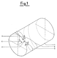
- 1 is the bobbin or cylindrical wound yarn package
- 2 and 4 are two successive reversal points on the side of the bobbin 1 under formation and therefore represent the commencement point 2 of the wound spiral 3 and the termination point 4 of the spiral 6 after one complete outward and return stroke of the known yarn guide element (not shown) which operates under traversing action for the cross-depositing of the yarn.
- Said points 2 and 4 define a circumferential arc subtending the angle C.
- Said wound yarn layers 5 and 10 form after a number OM of entire outward and return strokes of the yarn guide element, where OM is its current winding order; P1, P2, P3 whil, P18 are the reversal points of the yarn turns deposited along the side of the bobbin 1 on termination of a number of double beats of the yarn guide element equal to the current winding order OM, said OM double beats winding the yarn into several cross-turns distributed over the circumferential surface of the bobbin under formation, which increases its diameter xx by the thickness 5; R1, R2, R3 bib, R18 are the reversal points of the yarn turns deposited along the side of the bobbin 1 on termination of a number of double beats equal to the current winding order OM, said wound yarn turns increasing the diameter ⁇ of the hobbin 1 under formation by the thickness 10; F/2 is the circumferential arc representing the shift which enables the reversal points of two consecutive generic layers 5 and 10 of wound yarn not to be superimposed, ie
- Said circumferential arc F/2 is substantially one half of the circumferential arc F between two successive reversal points on the side of the bobbin 1 during the formation of the superimposed thicknesses of wound yarn 5 and 10;
- G is the distance between two turns of yarn wound on the generator of the bobbin 1 under formation during two consecutive outward and return strokes of the winding underway, ie during two consecutive double beats of the known yarn guide element, said distance G corresponding to the perpendicular distance S between said deposited turns of the two consecutive outward and return strokes; K1, K2, K3, K4, K5 etc.
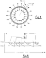
- curve portions K are the operative curve portions of the collection unit along which the known winding ratio has a constant value which is not a whole number or an exact fraction, said curve portions representing the positions of the operative points of the collection unit for which the successive distributed windings are obtained forming the superimposed thicknesses 5 and 10 of wound yarn and with the reversal points P and R uniformly distributed and spaced apart along the circumferential side of the bobbin 1 under formation.
- Said curve portions K are delimited by the horizontal winding angle lines representing the predetermined values ⁇ MIN and ⁇ MAX.
- the operator activates the collection winding unit by which the bobbin 1 is to be formed with continuous cross windings of synthetic yarn fed from a known spinning system, from which said yarn emerges at substantially constant speed.
- the electronic apparatus is then turned on to activate the method of the present invention, which controls the distribution of yarn on the bobbin 1 to be formed.
- the sensor 12 measures moment by moment the rotational speed of the motor 25, which rotates the known bobbin support mandrel.
- the advantageously electrical signal from the sensor 12 is fed moment by moment to a phase detector 20 after being subjected to a signal regulator 14 and an optoisolator 16, this latter being able to filter the signal disturbances and hence eliminate them to make said signal suitable for subsequent processing.
- said signal is amplified advantageously by a frequency multiplier 18.
- a sensor 11 measures moment by moment the speed of rotation of an induction motor 24 fed at variable frequency via an inverter 23.
- Said induction motor 24 operates a known cylindrical traverser cam with crossed helical grooves through which the spun yarn is wound onto the bobbin 1.
- the advantageously electrical signal from the sensor 11 is also fed, moment by moment, to a phase detector 20 after being subjected to a signal regulator 13 and an optoisolator 15, this latter being able to filter the signal disturbances and hence eliminate them to make said signal suitable for subsequent processing.
- phase detector 20 Before entering the said phase detector 20 said signal is amplified by a frequency multiplier 19.
- the two signals from the sensors 12 and 11 are compared and related in the phase detector 20 before being fed to the microprocessor 21, which calculates moment by moment the phase difference between said two signals.
- the phase difference is fed continuously to a converter 22, which converts the digital input signals into analog output signals.
- the analog signals are used moment by moment to activate the inverter 23 which controls the traverser cam motor 24 substantially continuously in order to deposit the wound yarn onto the surface of the bobbin 1 under formation in accordance with the method claimed in the present invention.
Landscapes
- Engineering & Computer Science (AREA)
- Textile Engineering (AREA)
- Winding Filamentary Materials (AREA)
- Replacing, Conveying, And Pick-Finding For Filamentary Materials (AREA)
Applications Claiming Priority (2)
| Application Number | Priority Date | Filing Date | Title |
|---|---|---|---|
| ITMI912842A IT1251429B (it) | 1991-10-25 | 1991-10-25 | Procedimento di distribuzione di filo in un gruppo bobinatore |
| ITMI912842 | 1991-10-25 |
Publications (1)
| Publication Number | Publication Date |
|---|---|
| EP0538961A1 true EP0538961A1 (de) | 1993-04-28 |
Family
ID=11360955
Family Applications (1)
| Application Number | Title | Priority Date | Filing Date |
|---|---|---|---|
| EP92203244A Ceased EP0538961A1 (de) | 1991-10-25 | 1992-10-22 | Verfahren zur Fadenführung auf einen Wickel in einer Aufspulvorrichtung |
Country Status (8)
| Country | Link |
|---|---|
| EP (1) | EP0538961A1 (de) |
| KR (1) | KR950011437B1 (de) |
| CN (1) | CN1081646A (de) |
| AR (1) | AR247531A1 (de) |
| IT (1) | IT1251429B (de) |
| MX (1) | MX9206104A (de) |
| TW (1) | TW255919B (de) |
| ZA (1) | ZA928232B (de) |
Cited By (2)
| Publication number | Priority date | Publication date | Assignee | Title |
|---|---|---|---|---|
| DE10018808A1 (de) * | 2000-04-15 | 2001-10-25 | Schlafhorst & Co W | Verfahren zum Herstellen von Kreuzspulen |
| CN102666335A (zh) * | 2009-10-30 | 2012-09-12 | 英威达技术有限公司 | 伸直长度和较高密度的膨松纱卷装及其制造方法 |
Families Citing this family (2)
| Publication number | Priority date | Publication date | Assignee | Title |
|---|---|---|---|---|
| CN101104489B (zh) * | 2006-07-14 | 2011-02-02 | 黄福庭 | 采用自适应控制的槽筒导纱电子防叠装置及方法 |
| CN112573289A (zh) * | 2021-02-24 | 2021-03-30 | 常州市新创智能科技有限公司 | 一种预浸料窄带收卷机构 |
Citations (5)
| Publication number | Priority date | Publication date | Assignee | Title |
|---|---|---|---|---|
| EP0055849A2 (de) * | 1980-12-31 | 1982-07-14 | Fritjof Dr.-Ing. Maag | Verfahren und Vorrichtung zur Herstellung von Garnspulen |
| EP0150771A2 (de) * | 1984-01-18 | 1985-08-07 | Fritjof Dr.-Ing. Maag | Präzisionsspule mit auf eine Spulenhülse aufgewickeltem Garn oder dergleichen, sowie Verfahren und Einrichtung zu deren Herstellung |
| EP0248406A2 (de) * | 1986-06-03 | 1987-12-09 | TEIJIN SEIKI CO. Ltd. | Überführungsapparat für Faden |
| EP0375043A1 (de) * | 1988-12-23 | 1990-06-27 | SAVIO S.p.A. | Verfahren zum Kontrollieren der Fadenführung auf einem Wickel in einer Aufspulvorrichtung für synthetische Fäden |
| EP0401781A1 (de) * | 1989-06-09 | 1990-12-12 | Fritjof Dr.-Ing. Maag | Präzisionskreuzspule, Verfahren zu deren Herstellung und Spuleinrichtung dafür |
-
1991
- 1991-10-25 IT ITMI912842A patent/IT1251429B/it active IP Right Grant
-
1992
- 1992-10-22 EP EP92203244A patent/EP0538961A1/de not_active Ceased
- 1992-10-23 AR AR92323487A patent/AR247531A1/es active
- 1992-10-23 MX MX9206104A patent/MX9206104A/es unknown
- 1992-10-23 ZA ZA928232A patent/ZA928232B/xx unknown
- 1992-10-24 TW TW081108514A patent/TW255919B/zh active
- 1992-10-24 CN CN92113340A patent/CN1081646A/zh active Pending
- 1992-10-26 KR KR1019920019696A patent/KR950011437B1/ko active IP Right Grant
Patent Citations (5)
| Publication number | Priority date | Publication date | Assignee | Title |
|---|---|---|---|---|
| EP0055849A2 (de) * | 1980-12-31 | 1982-07-14 | Fritjof Dr.-Ing. Maag | Verfahren und Vorrichtung zur Herstellung von Garnspulen |
| EP0150771A2 (de) * | 1984-01-18 | 1985-08-07 | Fritjof Dr.-Ing. Maag | Präzisionsspule mit auf eine Spulenhülse aufgewickeltem Garn oder dergleichen, sowie Verfahren und Einrichtung zu deren Herstellung |
| EP0248406A2 (de) * | 1986-06-03 | 1987-12-09 | TEIJIN SEIKI CO. Ltd. | Überführungsapparat für Faden |
| EP0375043A1 (de) * | 1988-12-23 | 1990-06-27 | SAVIO S.p.A. | Verfahren zum Kontrollieren der Fadenführung auf einem Wickel in einer Aufspulvorrichtung für synthetische Fäden |
| EP0401781A1 (de) * | 1989-06-09 | 1990-12-12 | Fritjof Dr.-Ing. Maag | Präzisionskreuzspule, Verfahren zu deren Herstellung und Spuleinrichtung dafür |
Non-Patent Citations (1)
| Title |
|---|
| MELLIAND TEXTILBERICHTE. INTERNATIONAL TEXTILE REPORTS vol. 66, no. 6, June 1985, HEIDELBERG (DE) pages 408 - 412 A. REBSAMEN 'Neuartige Möglichkeiten des Spulenaufbaus dank Mikroprozessor' * |
Cited By (3)
| Publication number | Priority date | Publication date | Assignee | Title |
|---|---|---|---|---|
| DE10018808A1 (de) * | 2000-04-15 | 2001-10-25 | Schlafhorst & Co W | Verfahren zum Herstellen von Kreuzspulen |
| CN102666335A (zh) * | 2009-10-30 | 2012-09-12 | 英威达技术有限公司 | 伸直长度和较高密度的膨松纱卷装及其制造方法 |
| CN102666335B (zh) * | 2009-10-30 | 2014-10-08 | 英威达技术有限公司 | 伸直长度和较高密度的膨松纱卷装及其制造方法 |
Also Published As
| Publication number | Publication date |
|---|---|
| IT1251429B (it) | 1995-05-09 |
| ZA928232B (en) | 1993-04-28 |
| ITMI912842A0 (it) | 1991-10-25 |
| KR950011437B1 (ko) | 1995-10-04 |
| AR247531A1 (es) | 1995-01-31 |
| CN1081646A (zh) | 1994-02-09 |
| TW255919B (de) | 1995-09-01 |
| KR930007785A (ko) | 1993-05-20 |
| ITMI912842A1 (it) | 1993-04-25 |
| MX9206104A (es) | 1993-04-01 |
Similar Documents
| Publication | Publication Date | Title |
|---|---|---|
| EP0630846B1 (de) | Verfahren und Vorrichtung zur Fadenverlegung auf einer Spule mit einer genuteten Antriebswalze | |
| EP0375043B1 (de) | Verfahren zum Kontrollieren der Fadenführung auf einem Wickel in einer Aufspulvorrichtung für synthetische Fäden | |
| US6186435B1 (en) | Method and apparatus for winding a yarn into a package | |
| US4798347A (en) | Method for winding filament yarns | |
| GB2127443A (en) | Method and traverse winding frame for winding a thread on a bobbin | |
| US4697753A (en) | Stepped precision winding process | |
| EP0248406B1 (de) | Überführungsapparat für Faden | |
| AT502782B1 (de) | Bandaufwickelverfahren | |
| US4789112A (en) | Yarn winding method and resulting package | |
| JPH06200429A (ja) | ワインダーに導入されるテープ状または糸状の巻取品を精密巻を有するチーズ巻にして巻き取る方法とその装置 | |
| EP0538961A1 (de) | Verfahren zur Fadenführung auf einen Wickel in einer Aufspulvorrichtung | |
| EP0260682B1 (de) | Verfahren zum Aufwickeln von Garn auf Spulen mit zugehöriger Maschine | |
| CN1263669C (zh) | 用于卷绕连续送进的纱线的方法和装置 | |
| DE3401530A1 (de) | Praezisionsspule, sowie verfahren und vorrichtung zu deren herstellung | |
| US4917319A (en) | Method of winding yarn packages | |
| EP0630845A1 (de) | Verfahren und Vorrichtung zur Fadenverlegung auf einer Spule mittels einer Antriebswalze und eines Fadenführers | |
| US3488938A (en) | Method and apparatus for winding yarn | |
| JPS58216868A (ja) | 粗ピツチ巻きで糸を巻取る際のリボン巻き発生を阻止する方法 | |
| EP0028109B1 (de) | Zylindrische Garn-Packung, Garnaufroll-Methode und Garnaufrollapparat | |
| EP1514824A1 (de) | Kreuzspule und Verfahren zu ihrer Herstellung | |
| US4135673A (en) | Method of avoiding or preventing low-order ribbon windings in the winding of filaments | |
| CN1140690A (zh) | 获得镜面干扰的方法 | |
| DE4239579A1 (de) | Verfahren zum Wickeln von Kreuzspulen | |
| JPH07256338A (ja) | 線条体用リール巻取機のトラバース制御装置 | |
| DE102013016644A1 (de) | Verfahren zum Betreiben einer Arbeitsstelle einer Kreuzspulen herstellenden Textilmaschine |
Legal Events
| Date | Code | Title | Description |
|---|---|---|---|
| PUAI | Public reference made under article 153(3) epc to a published international application that has entered the european phase |
Free format text: ORIGINAL CODE: 0009012 |
|
| AK | Designated contracting states |
Kind code of ref document: A1 Designated state(s): AT BE CH DE DK ES FR GB GR IE LI LU MC NL PT SE |
|
| 17P | Request for examination filed |
Effective date: 19930915 |
|
| 17Q | First examination report despatched |
Effective date: 19941208 |
|
| STAA | Information on the status of an ep patent application or granted ep patent |
Free format text: STATUS: THE APPLICATION HAS BEEN REFUSED |
|
| 18R | Application refused |
Effective date: 19950528 |