EP0538961A1 - Method for distributing yarn wound in a winding unit - Google Patents
Method for distributing yarn wound in a winding unit Download PDFInfo
- Publication number
- EP0538961A1 EP0538961A1 EP92203244A EP92203244A EP0538961A1 EP 0538961 A1 EP0538961 A1 EP 0538961A1 EP 92203244 A EP92203244 A EP 92203244A EP 92203244 A EP92203244 A EP 92203244A EP 0538961 A1 EP0538961 A1 EP 0538961A1
- Authority
- EP
- European Patent Office
- Prior art keywords
- yarn
- bobbin
- winding
- order
- wound
- Prior art date
- Legal status (The legal status is an assumption and is not a legal conclusion. Google has not performed a legal analysis and makes no representation as to the accuracy of the status listed.)
- Ceased
Links
Images

Classifications
-
- B—PERFORMING OPERATIONS; TRANSPORTING
- B65—CONVEYING; PACKING; STORING; HANDLING THIN OR FILAMENTARY MATERIAL
- B65H—HANDLING THIN OR FILAMENTARY MATERIAL, e.g. SHEETS, WEBS, CABLES
- B65H54/00—Winding, coiling, or depositing filamentary material
- B65H54/02—Winding and traversing material on to reels, bobbins, tubes, or like package cores or formers
- B65H54/38—Arrangements for preventing ribbon winding ; Arrangements for preventing irregular edge forming, e.g. edge raising or yarn falling from the edge
-
- B—PERFORMING OPERATIONS; TRANSPORTING
- B65—CONVEYING; PACKING; STORING; HANDLING THIN OR FILAMENTARY MATERIAL
- B65H—HANDLING THIN OR FILAMENTARY MATERIAL, e.g. SHEETS, WEBS, CABLES
- B65H2701/00—Handled material; Storage means
- B65H2701/30—Handled filamentary material
- B65H2701/31—Textiles threads or artificial strands of filaments
Definitions
- This invention relates to a method generally incorporating substantial improvements in the production of cross-wound bobbins for natural, drafted synthetic or non-drafted synthetic yarns, by which the formation of specular windings is avoided or reduced.
- the term “yarn” indicates any type of filiform material
- the term “bobbin” or “package” indicates any package of any shape of said material wound in substantially helical turns.
- the yarn has to be moved continuously to and fro in a direction parallel to the axis of rotation of the bobbin support mandrel.
- the present applicant is the proprietor of European Patent Appln. Public. No.0375043 relating to a method and relative apparatus for controlling the distribution of the yarn on the bobbin under formation in a synthetic yarn collection unit.
- This latter aspect involves the presence of points along the bobbin side at which there is an accumulation of material, with a high probability that the turns deposited at these points slide along the bobbin side to form fallen turns, which compromise correct subsequent unwinding of the yarn.
- This ribbing represents a winding defect in that by being deposited in superimposed turns, the yarn forms hard bands along the package, as is well known to the expert of the art. For clarity, this ribbing is known hereinafter as ribbing, banding or "mirror effects", the terms being used interchangeably.
- the yarn When a continuously fed yarn is cross-wound on a bobbin holder at high speed to form a package, the yarn is generally subjected to traversing, ie to alternate movements in opposite directions.
- the cited European Appln. Public. No. 0375043 of the present applicant proposes a method and relative apparatus for imposing a step-like distribution of yarn on the package under formation.
- the said winding ratio K varies in steps to assume values which are not a whole number, in order to prevent the said ribbing arising during yarn winding.
- said method has resulted in considerable improvement in the quality and characteristics of the cross-wound package under formation.
- the reversal points become superimposed on the side of the bobbin or thicken along narrow portions.
- This thickening means that the yarn is wound with greater compactness at these points, and in the limit the winding can undergo turn sliding or foliation along the side of the bobbin, forming " fallen turns".
- the method of the present invention obviates the aforesaid winding defects.
- the method enables the values of the winding parameters to be set moment by moment in such a manner that the collection unit operates along descending portions of curves, each portion consisting of points of a constant winding ratio K which is not a whole number, or which is not an exact fraction; said method, according to the present invention, comprising the following successive operating stages:
- the method of wound yarn distribution is also characterised by progressively winding successive turns collected as spirals positioned substantially centrally within the spirals wound during the immediately preceding to-and-fro stroke of travel.
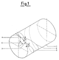
- 1 is the bobbin or cylindrical wound yarn package
- 2 and 4 are two successive reversal points on the side of the bobbin 1 under formation and therefore represent the commencement point 2 of the wound spiral 3 and the termination point 4 of the spiral 6 after one complete outward and return stroke of the known yarn guide element (not shown) which operates under traversing action for the cross-depositing of the yarn.
- Said points 2 and 4 define a circumferential arc subtending the angle C.
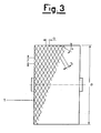
- Said wound yarn layers 5 and 10 form after a number OM of entire outward and return strokes of the yarn guide element, where OM is its current winding order; P1, P2, P3 whil, P18 are the reversal points of the yarn turns deposited along the side of the bobbin 1 on termination of a number of double beats of the yarn guide element equal to the current winding order OM, said OM double beats winding the yarn into several cross-turns distributed over the circumferential surface of the bobbin under formation, which increases its diameter xx by the thickness 5; R1, R2, R3 bib, R18 are the reversal points of the yarn turns deposited along the side of the bobbin 1 on termination of a number of double beats equal to the current winding order OM, said wound yarn turns increasing the diameter ⁇ of the hobbin 1 under formation by the thickness 10; F/2 is the circumferential arc representing the shift which enables the reversal points of two consecutive generic layers 5 and 10 of wound yarn not to be superimposed, ie
- Said circumferential arc F/2 is substantially one half of the circumferential arc F between two successive reversal points on the side of the bobbin 1 during the formation of the superimposed thicknesses of wound yarn 5 and 10;
- G is the distance between two turns of yarn wound on the generator of the bobbin 1 under formation during two consecutive outward and return strokes of the winding underway, ie during two consecutive double beats of the known yarn guide element, said distance G corresponding to the perpendicular distance S between said deposited turns of the two consecutive outward and return strokes; K1, K2, K3, K4, K5 etc.
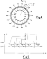
- curve portions K are the operative curve portions of the collection unit along which the known winding ratio has a constant value which is not a whole number or an exact fraction, said curve portions representing the positions of the operative points of the collection unit for which the successive distributed windings are obtained forming the superimposed thicknesses 5 and 10 of wound yarn and with the reversal points P and R uniformly distributed and spaced apart along the circumferential side of the bobbin 1 under formation.
- Said curve portions K are delimited by the horizontal winding angle lines representing the predetermined values ⁇ MIN and ⁇ MAX.
- the operator activates the collection winding unit by which the bobbin 1 is to be formed with continuous cross windings of synthetic yarn fed from a known spinning system, from which said yarn emerges at substantially constant speed.
- the electronic apparatus is then turned on to activate the method of the present invention, which controls the distribution of yarn on the bobbin 1 to be formed.
- the sensor 12 measures moment by moment the rotational speed of the motor 25, which rotates the known bobbin support mandrel.
- the advantageously electrical signal from the sensor 12 is fed moment by moment to a phase detector 20 after being subjected to a signal regulator 14 and an optoisolator 16, this latter being able to filter the signal disturbances and hence eliminate them to make said signal suitable for subsequent processing.
- said signal is amplified advantageously by a frequency multiplier 18.
- a sensor 11 measures moment by moment the speed of rotation of an induction motor 24 fed at variable frequency via an inverter 23.
- Said induction motor 24 operates a known cylindrical traverser cam with crossed helical grooves through which the spun yarn is wound onto the bobbin 1.
- the advantageously electrical signal from the sensor 11 is also fed, moment by moment, to a phase detector 20 after being subjected to a signal regulator 13 and an optoisolator 15, this latter being able to filter the signal disturbances and hence eliminate them to make said signal suitable for subsequent processing.
- phase detector 20 Before entering the said phase detector 20 said signal is amplified by a frequency multiplier 19.
- the two signals from the sensors 12 and 11 are compared and related in the phase detector 20 before being fed to the microprocessor 21, which calculates moment by moment the phase difference between said two signals.
- the phase difference is fed continuously to a converter 22, which converts the digital input signals into analog output signals.
- the analog signals are used moment by moment to activate the inverter 23 which controls the traverser cam motor 24 substantially continuously in order to deposit the wound yarn onto the surface of the bobbin 1 under formation in accordance with the method claimed in the present invention.
Abstract
This invention relates to a method for distributing yarn wound onto a bobbin under formation in a collection unit in which the cross-winding starts with a high minimum collection order, said method including varying the relative rotational ratio between the mandrel and traverser cam at each completion of a number of double beats equal to the current winding order in order to effect precise controlled shifting, by which no superimposing of the reversal points of the yarn turns deposited along the side of the bobbin takes place during the entire wound yarn collection process.
Description
- This invention relates to a method generally incorporating substantial improvements in the production of cross-wound bobbins for natural, drafted synthetic or non-drafted synthetic yarns, by which the formation of specular windings is avoided or reduced.
- More specifically, it relates to improvements in a method for automatically winding a yarn onto a cylindrical bobbin, on which said yarn is deposited as successive spirals positioned substantially centrally within each other and with the reversal points of the yarn turns being distributed uniformly along the bobbin sides during the progression of to-and-fro movements in the wound yarn collection process.
- In the ensuing description and claims the term "yarn" indicates any type of filiform material, and the term "bobbin" or "package" indicates any package of any shape of said material wound in substantially helical turns. Moreover, as is well known, in collecting the yarn on a bobbin by cross-turn distribution, the yarn has to be moved continuously to and fro in a direction parallel to the axis of rotation of the bobbin support mandrel.
- This action is known as "traversing".
- Various automatic winding methods and apparatus have been previously proposed in which a yarn is collected at a substantially constant rate during the formation of the package.
- The present applicant is the proprietor of European Patent Appln. Public. No.0375043 relating to a method and relative apparatus for controlling the distribution of the yarn on the bobbin under formation in a synthetic yarn collection unit.
- With reference to this field of the art relating to known winding in a synthetic yarn collection unit, the problem of imperfections in distribution during the collection of the yarn on the package under formation is very important. Collection units for producing yarn packages nearly always lead to the formation of deposits of turns concentrated at certain points, to give rise to ribbing and also often to the superimposing of reversal points along the circumferential sides of the bobbin under formation.
- This latter aspect involves the presence of points along the bobbin side at which there is an accumulation of material, with a high probability that the turns deposited at these points slide along the bobbin side to form fallen turns, which compromise correct subsequent unwinding of the yarn. This ribbing represents a winding defect in that by being deposited in superimposed turns, the yarn forms hard bands along the package, as is well known to the expert of the art. For clarity, this ribbing is known hereinafter as ribbing, banding or "mirror effects", the terms being used interchangeably.
- When a continuously fed yarn is cross-wound on a bobbin holder at high speed to form a package, the yarn is generally subjected to traversing, ie to alternate movements in opposite directions.
- In this winding process, if the ratio K of the number of revolutions N of the bobbin holder to the number OM of double beats of the traverser is a whole number, the yarn tends to wind onto those yarn turns which have been previously wound on the bobbin, so making the outer perimetral surface of the package irregular, to the extent of forming hard layers of superimposed yarn, ie of high density ribbing, which compromise correct subsequent unwinding of the yarn, or compromise uniformity of liquid passage through dyeworks bobbins, with consequent layers not coloured uniformly, to result in periodic variations in the colour tint of the yarn. To overcome these drawbacks, a fractional winding ratio has to be chosen in order to give the turns a suitable slight shift relative to the turn which has preceded it. To prevent these problems arising, the cited European Appln. Public. No. 0375043 of the present applicant proposes a method and relative apparatus for imposing a step-like distribution of yarn on the package under formation. In this method, the said winding ratio K varies in steps to assume values which are not a whole number, in order to prevent the said ribbing arising during yarn winding. In effect, said method has resulted in considerable improvement in the quality and characteristics of the cross-wound package under formation.
- However, hardened yarn layers or improper yarn positioning in a cross-wound package still sometimes occurs.
- In this respect, the reversal points become superimposed on the side of the bobbin or thicken along narrow portions. This thickening means that the yarn is wound with greater compactness at these points, and in the limit the winding can undergo turn sliding or foliation along the side of the bobbin, forming "fallen turns".
- From observing the aforesaid disadvantages of the preceding method, the inventors of this patent application have surprisingly found that the method of the present invention obviates the aforesaid winding defects. To this end, the method enables the values of the winding parameters to be set moment by moment in such a manner that the collection unit operates along descending portions of curves, each portion consisting of points of a constant winding ratio K which is not a whole number, or which is not an exact fraction; said method, according to the present invention, comprising the following successive operating stages:
- starting the cross-winding with a sufficiently high minimum collection order OM of a whole number preferably equal to or greater than 13, to advantageously allow the superimposing of turns only after a sufficiently large number of double beats;
- varying the relative rotational ratio between the mandrel and the traverser cam at each completion of a number of double beats equal to the current winding order OM, which corresponds exactly to the number of reversal points along the entire circumference of the sides of the bobbin under formation, in order to effect a precise controlled shift, which enables no superimposing of the reversal points of the yarn turns deposited along the side of the bobbin to occur during the entire wound yarn collection process;
- multiplying, moment by moment, the frequency of the signals originating from the mandrel rotational speed sensors by a whole number equal to the current winding order and hence equal to the whole-number OM value of the denominator of the winding ratio K;
- multiplying, moment by moment, the frequency of the signals originating from the traversing cam rotational speed sensors by a whole number equal to the whole-number value of the numerator N of the winding ratio K;
- comparing said multiplied values to couple them in phase, ie to synchronize them in order to reduce the effects due to possible disturbances, so as to nullify any phase error during the progressive wound yarn collection.
- The method of wound yarn distribution is also characterised by progressively winding successive turns collected as spirals positioned substantially centrally within the spirals wound during the immediately preceding to-and-fro stroke of travel.
- The characteristics and advantages of the method according to the invention will be more apparent from the description given hereinafter with reference to the accompanying drawings in which:
- Figure 1 is an isometric schematic view of a yarn bobbin wound with two successive spirals shown at their points of reversal along the circumference of one side of the bobbin under formation;
- Figure 2 is a block flow diagram showing the operational sequence of the essential stages in implementing the method of the invention;
- Figure 3 is a schematic frontal view of a wound yarn bobbin showing the geometrical quantities involved in the precision winding in accordance with the invention;
- Figure 4 is a schematic front section through two superimposed adjacent layers of yarn wound such that their reversal points extend along the entire circumference of the bobbin side, said view showing the shift in position of the reversal points of the two adjacent layers;
- Figure 5 is a diagram showing some curves for a constant non-whole number winding ratio K with the relative OM winding order numbers, said figure also showing the horizontal lines delimiting said curves at the maximum and minimum winding angle.
- In the figures, identical parts or parts of identical function carry the same reference numerals. Furthermore for overall clarity, in the figures the winding unit for collecting the wound yarn and the parts not necessary for understanding the invention are either omitted or shown generically as they are of known type.
- In said accompanying figures:
1 is the bobbin or cylindrical wound yarn package; 2 and 4 are two successive reversal points on the side of thebobbin 1 under formation and therefore represent thecommencement point 2 of thewound spiral 3 and thetermination point 4 of thespiral 6 after one complete outward and return stroke of the known yarn guide element (not shown) which operates under traversing action for the cross-depositing of the yarn. Saidpoints - Said angle C when multiplied by the whole-number value of the current winding order results in a round angle of 360°, and hence a complete revolution of the reversal points on the side of the
bobbin 1 under formation; α is the inclination of the winding spirals, said angle α varying during the winding between predetermined αMIN and αMAX values (see Figure 5); 5 is any inner layer of wound yarn lying below anyoverlying layer 10 of wound yarn. Saidwound yarn layers bobbin 1 on termination of a number of double beats of the yarn guide element equal to the current winding order OM, said OM double beats winding the yarn into several cross-turns distributed over the circumferential surface of the bobbin under formation, which increases its diameter xx by thethickness 5; R1, R2, R3 ....., R18 are the reversal points of the yarn turns deposited along the side of thebobbin 1 on termination of a number of double beats equal to the current winding order OM, said wound yarn turns increasing the diameter ⌀ of thehobbin 1 under formation by thethickness 10; F/2 is the circumferential arc representing the shift which enables the reversal points of two consecutivegeneric layers bobbin 1 during the formation of the superimposed thicknesses ofwound yarn bobbin 1 under formation during two consecutive outward and return strokes of the winding underway, ie during two consecutive double beats of the known yarn guide element, said distance G corresponding to the perpendicular distance S between said deposited turns of the two consecutive outward and return strokes; K1, K2, K3, K4, K5 etc. are the operative curve portions of the collection unit along which the known winding ratio has a constant value which is not a whole number or an exact fraction, said curve portions representing the positions of the operative points of the collection unit for which the successive distributed windings are obtained forming thesuperimposed thicknesses bobbin 1 under formation. Said curve portions K are delimited by the horizontal winding angle lines representing the predetermined values αMIN and αMAX. - The following description of operation, with reference to the said figures, relates particularly to that which is new and therefore examines only such stages of the method of the present invention, no description being given of devices and operating means of the known art used for implementing the stages of said method.
- The operator activates the collection winding unit by which the
bobbin 1 is to be formed with continuous cross windings of synthetic yarn fed from a known spinning system, from which said yarn emerges at substantially constant speed. - The electronic apparatus is then turned on to activate the method of the present invention, which controls the distribution of yarn on the
bobbin 1 to be formed. - The
sensor 12 measures moment by moment the rotational speed of the motor 25, which rotates the known bobbin support mandrel. The advantageously electrical signal from thesensor 12 is fed moment by moment to aphase detector 20 after being subjected to asignal regulator 14 and anoptoisolator 16, this latter being able to filter the signal disturbances and hence eliminate them to make said signal suitable for subsequent processing. - Before entering the said
phase detector 20 said signal is amplified advantageously by a frequency multiplier 18. - Simultaneously, and hence superimposed in time, a
sensor 11 measures moment by moment the speed of rotation of aninduction motor 24 fed at variable frequency via aninverter 23. Saidinduction motor 24 operates a known cylindrical traverser cam with crossed helical grooves through which the spun yarn is wound onto thebobbin 1. The advantageously electrical signal from thesensor 11 is also fed, moment by moment, to aphase detector 20 after being subjected to asignal regulator 13 and anoptoisolator 15, this latter being able to filter the signal disturbances and hence eliminate them to make said signal suitable for subsequent processing. - Before entering the said
phase detector 20 said signal is amplified by afrequency multiplier 19. The two signals from thesensors phase detector 20 before being fed to themicroprocessor 21, which calculates moment by moment the phase difference between said two signals. - The phase difference is fed continuously to a
converter 22, which converts the digital input signals into analog output signals. - The analog signals are used moment by moment to activate the
inverter 23 which controls thetraverser cam motor 24 substantially continuously in order to deposit the wound yarn onto the surface of thebobbin 1 under formation in accordance with the method claimed in the present invention. - It is apparent that the description is given purely by way of non-limiting example, and that modifications can be made thereto but without leaving the scope of protection of the invention.
Claims (2)
- A method for distributing yarn wound onto a bobbin under formation in a collection unit provided both with a bobbin support mandrel driven at adjustable rotational speed, and with a control roller which remains constantly in contact with the increasing-diameter outer circumference of the package under formation and also remains in contact with a traverser cam rotated by a drive source, said method being characterised by comprising the following stages:- starting the cross-winding with a sufficiently high minimum collection order of a whole number preferably equal to or greater than 13, to advantageously allow the superimposing of turns only after a sufficiently large number of double beats;- varying the relative rotational ratio between the mandrel and the traverser cam at each completion of a number of double beats equal to the current winding order, which corresponds exactly to the number of reversal points along the entire circumference of the sides of the bobbin under formation, in order to effect a precise controlled shift, which enables no superimposing of the reversal points of the yarn turns deposited along the side of the bobbin to occur during the entire wound yarn collection process;- multiplying, moment by moment, the frequency of the signals originating from the mandrel rotational speed sensors by a whole number equal to the current winding order and hence equal to the whole-number OM value of the denominator of the winding ratio;- multiplying, moment by moment, the frequency of the signals originating from the traverser cam rotational speed sensors by a whole number equal to the whole-number value of the numerator N of the winding ratio K;- comparing said multiplied values to couple them in phase, ie to synchronize them in order to reduce the effects due to possible disturbances, so as to nullify any phase error during the progressive wound yarn collection.
- A method for distributing yarn wound onto a bobbin under formation in a collection unit as claimed in claim 1, characterised by progressively winding successive turns collected as spirals positioned substantially centrally within the spirals wound during the immediately preceding to-and-fro stroke of travel.
Applications Claiming Priority (2)
| Application Number | Priority Date | Filing Date | Title |
|---|---|---|---|
| ITMI912842 | 1991-10-25 | ||
| ITMI912842A IT1251429B (en) | 1991-10-25 | 1991-10-25 | WIRE DISTRIBUTION PROCEDURE IN A SPOOLER GROUP |
Publications (1)
| Publication Number | Publication Date |
|---|---|
| EP0538961A1 true EP0538961A1 (en) | 1993-04-28 |
Family
ID=11360955
Family Applications (1)
| Application Number | Title | Priority Date | Filing Date |
|---|---|---|---|
| EP92203244A Ceased EP0538961A1 (en) | 1991-10-25 | 1992-10-22 | Method for distributing yarn wound in a winding unit |
Country Status (8)
| Country | Link |
|---|---|
| EP (1) | EP0538961A1 (en) |
| KR (1) | KR950011437B1 (en) |
| CN (1) | CN1081646A (en) |
| AR (1) | AR247531A1 (en) |
| IT (1) | IT1251429B (en) |
| MX (1) | MX9206104A (en) |
| TW (1) | TW255919B (en) |
| ZA (1) | ZA928232B (en) |
Cited By (2)
| Publication number | Priority date | Publication date | Assignee | Title |
|---|---|---|---|---|
| DE10018808A1 (en) * | 2000-04-15 | 2001-10-25 | Schlafhorst & Co W | Winding cross wound bobbins uses measurements of the yarn diameter to compute the lay of the yarns around the bobbin in a cross winding with consistent characteristics |
| CN102666335A (en) * | 2009-10-30 | 2012-09-12 | 英威达技术有限公司 | Extended length and higher density packages of bulky yarns and methods of making the same |
Families Citing this family (2)
| Publication number | Priority date | Publication date | Assignee | Title |
|---|---|---|---|---|
| CN101104489B (en) * | 2006-07-14 | 2011-02-02 | 黄福庭 | Groove drum guide yarn electric folding-proof device employing self-adapting control and method thereof |
| CN112573289A (en) * | 2021-02-24 | 2021-03-30 | 常州市新创智能科技有限公司 | Prepreg narrow-band winding mechanism |
Citations (5)
| Publication number | Priority date | Publication date | Assignee | Title |
|---|---|---|---|---|
| EP0055849A2 (en) * | 1980-12-31 | 1982-07-14 | Fritjof Dr.-Ing. Maag | Method and device for winding yarn |
| EP0150771A2 (en) * | 1984-01-18 | 1985-08-07 | Fritjof Dr.-Ing. Maag | Precision wound package, process and device for its manufacture |
| EP0248406A2 (en) * | 1986-06-03 | 1987-12-09 | TEIJIN SEIKI CO. Ltd. | Yarn traverse apparatus |
| EP0375043A1 (en) * | 1988-12-23 | 1990-06-27 | SAVIO S.p.A. | Process for controlling distribution of thread on a package in a collection unit for synthetic threads |
| EP0401781A1 (en) * | 1989-06-09 | 1990-12-12 | Fritjof Dr.-Ing. Maag | Precision wound yarn package, method for its production and device for making same |
-
1991
- 1991-10-25 IT ITMI912842A patent/IT1251429B/en active IP Right Grant
-
1992
- 1992-10-22 EP EP92203244A patent/EP0538961A1/en not_active Ceased
- 1992-10-23 MX MX9206104A patent/MX9206104A/en unknown
- 1992-10-23 ZA ZA928232A patent/ZA928232B/en unknown
- 1992-10-23 AR AR92323487A patent/AR247531A1/en active
- 1992-10-24 CN CN92113340A patent/CN1081646A/en active Pending
- 1992-10-24 TW TW081108514A patent/TW255919B/zh active
- 1992-10-26 KR KR1019920019696A patent/KR950011437B1/en active IP Right Grant
Patent Citations (5)
| Publication number | Priority date | Publication date | Assignee | Title |
|---|---|---|---|---|
| EP0055849A2 (en) * | 1980-12-31 | 1982-07-14 | Fritjof Dr.-Ing. Maag | Method and device for winding yarn |
| EP0150771A2 (en) * | 1984-01-18 | 1985-08-07 | Fritjof Dr.-Ing. Maag | Precision wound package, process and device for its manufacture |
| EP0248406A2 (en) * | 1986-06-03 | 1987-12-09 | TEIJIN SEIKI CO. Ltd. | Yarn traverse apparatus |
| EP0375043A1 (en) * | 1988-12-23 | 1990-06-27 | SAVIO S.p.A. | Process for controlling distribution of thread on a package in a collection unit for synthetic threads |
| EP0401781A1 (en) * | 1989-06-09 | 1990-12-12 | Fritjof Dr.-Ing. Maag | Precision wound yarn package, method for its production and device for making same |
Non-Patent Citations (1)
| Title |
|---|
| MELLIAND TEXTILBERICHTE. INTERNATIONAL TEXTILE REPORTS vol. 66, no. 6, June 1985, HEIDELBERG (DE) pages 408 - 412 A. REBSAMEN 'Neuartige Möglichkeiten des Spulenaufbaus dank Mikroprozessor' * |
Cited By (3)
| Publication number | Priority date | Publication date | Assignee | Title |
|---|---|---|---|---|
| DE10018808A1 (en) * | 2000-04-15 | 2001-10-25 | Schlafhorst & Co W | Winding cross wound bobbins uses measurements of the yarn diameter to compute the lay of the yarns around the bobbin in a cross winding with consistent characteristics |
| CN102666335A (en) * | 2009-10-30 | 2012-09-12 | 英威达技术有限公司 | Extended length and higher density packages of bulky yarns and methods of making the same |
| CN102666335B (en) * | 2009-10-30 | 2014-10-08 | 英威达技术有限公司 | Extended length and higher density packages of bulky yarns and methods of making the same |
Also Published As
| Publication number | Publication date |
|---|---|
| ZA928232B (en) | 1993-04-28 |
| KR950011437B1 (en) | 1995-10-04 |
| AR247531A1 (en) | 1995-01-31 |
| TW255919B (en) | 1995-09-01 |
| CN1081646A (en) | 1994-02-09 |
| MX9206104A (en) | 1993-04-01 |
| KR930007785A (en) | 1993-05-20 |
| IT1251429B (en) | 1995-05-09 |
| ITMI912842A1 (en) | 1993-04-25 |
| ITMI912842A0 (en) | 1991-10-25 |
Similar Documents
| Publication | Publication Date | Title |
|---|---|---|
| EP0630846B1 (en) | Method and apparatus for distributing wound yarn on a bobbin driven by a grooved roller | |
| EP0375043B1 (en) | Process for controlling distribution of thread on a package in a collection unit for synthetic threads | |
| US6186435B1 (en) | Method and apparatus for winding a yarn into a package | |
| US4798347A (en) | Method for winding filament yarns | |
| GB2127443A (en) | Method and traverse winding frame for winding a thread on a bobbin | |
| US4697753A (en) | Stepped precision winding process | |
| EP0248406B1 (en) | Yarn traverse apparatus | |
| AT502782B1 (en) | BANDAUFWICKELVERFAHREN | |
| US4789112A (en) | Yarn winding method and resulting package | |
| JPH06200429A (en) | Method and apparatus for winding tape-like or yarn-like wound article introduced into winder as cheese winding with precise winding | |
| EP0538961A1 (en) | Method for distributing yarn wound in a winding unit | |
| US4485978A (en) | Method and apparatus for winding strand upon spools having tapered end flanges | |
| EP0260682B1 (en) | Method of winding yarn on bobbin and machine therefor | |
| CN1263669C (en) | Method and device for windig a continuously fed thread | |
| DE3401530A1 (en) | PRECISION COIL, METHOD AND DEVICE FOR PRODUCING THE SAME | |
| GB1562733A (en) | Method and apparatus for doubling and twisting a yarn by a two-step changeover system | |
| US4917319A (en) | Method of winding yarn packages | |
| EP0630845A1 (en) | Method and apparatus for distributing wound yarn on a bobbin by means of a drive roller and a yarn guide | |
| US3488938A (en) | Method and apparatus for winding yarn | |
| JPS58216868A (en) | Method of preventing generation of ribbon winding in case when yarn is rolled through rough pitch winding | |
| EP0028109B1 (en) | Cylindrical-bodied yarn package, method of winding yarn and a yarn winding apparatur | |
| EP1514824A1 (en) | Crosswound bobbin and method for producing of such a bobbin | |
| US4135673A (en) | Method of avoiding or preventing low-order ribbon windings in the winding of filaments | |
| CN1140690A (en) | Method for obtaining mirror interference | |
| JPH07256338A (en) | Traverse control device for reel coiling machine for wire |
Legal Events
| Date | Code | Title | Description |
|---|---|---|---|
| PUAI | Public reference made under article 153(3) epc to a published international application that has entered the european phase |
Free format text: ORIGINAL CODE: 0009012 |
|
| AK | Designated contracting states |
Kind code of ref document: A1 Designated state(s): AT BE CH DE DK ES FR GB GR IE LI LU MC NL PT SE |
|
| 17P | Request for examination filed |
Effective date: 19930915 |
|
| 17Q | First examination report despatched |
Effective date: 19941208 |
|
| STAA | Information on the status of an ep patent application or granted ep patent |
Free format text: STATUS: THE APPLICATION HAS BEEN REFUSED |
|
| 18R | Application refused |
Effective date: 19950528 |