CN1081646A - Be used to distribute and be wound on method of yarn on the winding unit - Google Patents
Be used to distribute and be wound on method of yarn on the winding unit Download PDFInfo
- Publication number
- CN1081646A CN1081646A CN92113340A CN92113340A CN1081646A CN 1081646 A CN1081646 A CN 1081646A CN 92113340 A CN92113340 A CN 92113340A CN 92113340 A CN92113340 A CN 92113340A CN 1081646 A CN1081646 A CN 1081646A
- Authority
- CN
- China
- Prior art keywords
- yarn
- coiling
- yarn tube
- tube
- little
- Prior art date
- Legal status (The legal status is an assumption and is not a legal conclusion. Google has not performed a legal analysis and makes no representation as to the accuracy of the status listed.)
- Pending
Links
- 238000000034 method Methods 0.000 title claims abstract description 39
- 238000004804 winding Methods 0.000 title claims abstract description 17
- 230000008569 process Effects 0.000 claims abstract description 16
- 230000004087 circulation Effects 0.000 claims abstract description 6
- 230000008859 change Effects 0.000 claims abstract description 4
- 238000006073 displacement reaction Methods 0.000 claims abstract description 4
- 238000007493 shaping process Methods 0.000 claims description 9
- 230000001360 synchronised effect Effects 0.000 claims description 2
- 238000000465 moulding Methods 0.000 abstract 1
- 230000008901 benefit Effects 0.000 description 3
- 230000015572 biosynthetic process Effects 0.000 description 2
- 230000002950 deficient Effects 0.000 description 2
- 238000004043 dyeing Methods 0.000 description 2
- 230000000694 effects Effects 0.000 description 2
- 230000006872 improvement Effects 0.000 description 2
- 230000006698 induction Effects 0.000 description 2
- 239000000463 material Substances 0.000 description 2
- 208000034189 Sclerosis Diseases 0.000 description 1
- 238000009825 accumulation Methods 0.000 description 1
- 230000000712 assembly Effects 0.000 description 1
- 238000000429 assembly Methods 0.000 description 1
- 230000005540 biological transmission Effects 0.000 description 1
- 238000004891 communication Methods 0.000 description 1
- 238000007596 consolidation process Methods 0.000 description 1
- 230000007547 defect Effects 0.000 description 1
- 238000010586 diagram Methods 0.000 description 1
- 238000005516 engineering process Methods 0.000 description 1
- 230000001788 irregular Effects 0.000 description 1
- 239000007788 liquid Substances 0.000 description 1
- 238000004519 manufacturing process Methods 0.000 description 1
- 230000008719 thickening Effects 0.000 description 1
Images


Classifications
-
- B—PERFORMING OPERATIONS; TRANSPORTING
- B65—CONVEYING; PACKING; STORING; HANDLING THIN OR FILAMENTARY MATERIAL
- B65H—HANDLING THIN OR FILAMENTARY MATERIAL, e.g. SHEETS, WEBS, CABLES
- B65H54/00—Winding, coiling, or depositing filamentary material
- B65H54/02—Winding and traversing material on to reels, bobbins, tubes, or like package cores or formers
- B65H54/38—Arrangements for preventing ribbon winding ; Arrangements for preventing irregular edge forming, e.g. edge raising or yarn falling from the edge
-
- B—PERFORMING OPERATIONS; TRANSPORTING
- B65—CONVEYING; PACKING; STORING; HANDLING THIN OR FILAMENTARY MATERIAL
- B65H—HANDLING THIN OR FILAMENTARY MATERIAL, e.g. SHEETS, WEBS, CABLES
- B65H2701/00—Handled material; Storage means
- B65H2701/30—Handled filamentary material
- B65H2701/31—Textiles threads or artificial strands of filaments
Abstract
The present invention relates to distribution coiling method of yarn on the yarn tube in a kind of moulding in a wind2, begin to carry out cross winding with very little coiling approximate number, described method is included in and finishes some each time, equal two circulation times of existing coiling approximate number, change the relative rotation ratio between mandrel and the traverse gear cam, make whereby and in the process of whole coiling yarn, do not produce turn back a little overlapping of the yarn circle that distributes along yarn tube side so that reach precisely controlling displacement.
Description
The present invention relates to a kind of method, this method can make it remarkable improvement to the production of being carried out the yarn tube of cross winding by nature, that drawing is synthetic or the synthetic yarn of non-drawing at large, can avoid or reduce the formation of (Specular) coiling of reflection shape thus.More particularly, it relates to a kind of with the development of method of yarn auto reeling to the cylindrical yarn tube, described yarn is distributed in middle body each other, basically press the continuous helical line attached on this yarn tube, and in the process of coiling yarn, during yarn moves back and forth, have some along yarn tube side well-distributed yarn circle and turn back a little.
In afterwards the explanation and claim, term " yarn " is meant any filamentary material, and term " bobbin " or " assembly " are any assemblies of instigating the Any shape that described material reels with helix line basically.In addition, know as many institutes, on the yarn tube in the coiling yarn, yarn must move by successive reciprocation on the direction of the rotation axis that is parallel to yarn tube supporting mandrel in the distribution mode of utilizing cross winding.This motion is called " traversing ".
In the past, proposed various auto reeling method and apparatus, in the process that assembly forms, yarn is reeled by constant rate of speed basically.The applicant is that publication number is everyone of 0375043 european patent application, and this patent application relates in a kind of synthetic threads wind2, is used to control method and the relevant device thereof that yarn distributes in yarn tube forming process.
With reference to the known relevant coiling technology in this field in the synthetic threads wind2, in the assembly forming process, during the coiling yarn, the defect problem of yarn distribution aspect is very serious.The wind2 that is used to produce the yarn assembly almost always causes concentrating on some point to be gone up and forms the yarn circle and pile up, produce projection and form rib, and on the circumference side of the yarn tube that is being shaped, often cause turn back a little overlapping.The back comprises on the one hand along the more such points of yarn tube side existence, in this place's yarn accumulation, may make very much the yarn circle that is deposited in this point form the yarn circle that comes off along yarn tube side slip, and this just hinders yarn and unclamps according to normal sequence.It is a kind of coiling defective that this rib exists, and is piled up by the overlapping yarns circle to produce, and yarn forms hard tape along assembly, as this area professional is known.For the sake of clarity, this rib hereinafter is called rib respectively, tape or " image effect " (mirror effects), and these terms are interchangeable.
The high speed cross winding is when forming an assembly on yarn tube supporter when the yarn of continuous supply, and yarn generally is subjected to traversing, promptly alternately moves in the opposite direction.In this winding process, if, the ratio K of two circulations (doublebeat) number OM of the revolution N of yarn tube supporter and horizontal mobile device is an integer, yarn certainly will be on those yarn circles that before have been wound on the yarn tube, make the circumferential outer surface of assembly produce irregular, form the hardened layer of overlapping yarn, it is highdensity rib, its infringement yarn is by normally unclamping continuously, perhaps infringement is through the homogeneity of the liquid communication of dyeing bobbin, cause continuous line layer dyeing inhomogeneous, make the color of yarn produce cyclical variation.In order to overcome this shortcoming, must select mark coiling ratio, so that make the yarn circle produce suitable slight displacement with respect to the yarn circle of before having reeled.In order to prevent that these problems from occurring, the publication number that the applicant quotes is that 0375043 European application has proposed a kind of a kind of stepped distribution method of yarn and relevant device thereof of applying on the assembly that is being shaped.In the method, described coiling ratio K progressively changes a non-integral assumed value, to prevent occurring described rib in the yarn winding process.In fact, described method has caused producing sizable improvement at the quality and the aspect of performance of the assembly that forms cross winding.
Yet the thread layers of sclerosis or bad yarn still can produce in the assembly of a cross winding sometimes.
In this respect, the turn back side that a little overlaps the yarn tube or thicken along crevice.This thickening means, on these aspects, reel for yarn around consolidation more, under the situation of the limit, make coiling may produce the slippage of yarn circle or peel off along yarn tube side, form by " the yarn circle that comes off ".
From above-mentioned observation to the methodical shortcoming of elder generation, the discovery that the contriver of present patent application is surprising method of the present invention has been avoided above-mentioned coiling defective.For this reason, this method can make the numerical value of coiling parameter set according to a kind of like this mode at any time, be the sloping portion work of wind2 along curve, each part is made up of the point with constant coiling ratio K, K is not an integer or is not (exact) mark of a strictness that the described method that proposes according to the present invention comprises following continuous handling step:
-beginning cross winding with a very little coiling approximate number OM, OM is an integer, preferably is equal to or greater than 13, so that help making that the overlapping of yarn circle occurs over just after enough big two loop number.
-finish some each time, equal two circulation times of existing coiling approximate number OM, the relative rotation ratio of change between mandrel and traverse gear cam, this OM strictness is counted corresponding to the turning back of whole circumference side of the yarn tube in being shaped, be a little overlapping of turning back that in the process of whole coiling yarn, does not produce yarn circle that tube along the line side distributes in order to reach precisely controlling displacement, to make;
-will obtain s-f by the mandrel rotation speed sensor at any time to multiply by an integer that equals existing coiling approximate number, and the value of the integer OM of the denominator of the ratio K that therefore equals to reel;
-will multiply by an integer of the molecule N numerical value of the ratio K that equals to reel at any time by the frequency that traverse gear cam rotation speed sensor obtains signal;
-more described two product values interrelate them aspect phase place, even they are synchronous, so that reduce the influence of the interference that may exist, thereby eliminate phase deviation in yarn winding process in sequence.
The feature of the method that the coiling yarn distributes also is in above-mentioned reciprocating travel of advancing, sequential volume around continuous yarn circle press helix line and reel, it is distributed in the interior middle body of screw type spiral basically.
Characteristics according to the proposed method and advantage, by the reference accompanying drawing, will be more obvious by hereinafter being described, wherein:
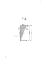
Fig. 1 is the isogonism scheme drawing of yarn tube, the circumference of a side of the yarn tube in be shaped, and the yarn tube is wound with two continuous helix lines and is illustrated in its place of turning back;
Fig. 2 is a block flow diagram, and it is illustrated in the job order of the basic step when implementing the inventive method;
Fig. 3 is the forward scheme drawing of the yarn tube of a coiling, and its expression is included in the geometric sense in the accurate coiling that proposes according to the present invention;
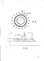
Fig. 4 is the forward scheme drawing that runs through two overlapping, adjacent yarn winding layers, and the turning back a little to stretch along the whole circumference of yarn tube side of yarn distributes, and described view has represented that the position that two adjacent layers are turned back a little moves;
Fig. 5 is a scheme drawing, and its expression has some curves of a constant non-integer coiling ratio K of relative OM coiling approximate number numeral, and this figure also is illustrated in the horizon that minimum and maximum winding angle place determines described curve.
In these figure, same part or the part with said function indicate identical reference number symbol.Also promisingly make profile clear, in these figure, or or be used to accumulate the wind2 of coiling yarn and ignore expression usually for understanding the nonessential part of the present invention, because they all are known patterns.
In described accompanying drawing:
The 1st, yarn tube or cylindrical around the yarn assembly; 2 and 4 is two continuous turning back a little on the yarn tube side in being shaped, and the initial point 2 of expression coiling helix line 3 and the terminal point 4 of helix line 6, this terminal point is after the outside and complete stroke that return of a known thread guide elements (not shown), and this director element is worked according to the side travel mode for the cross-over configuration yarn.Described point 2 and the point 4 one section circular arc that limits angle of entry C.
Described angle C is when the integral value with existing coiling approximate number multiplies each other, one 360 ° angle in circular segment consequently, therefore be a little the complete cycle of respectively turning back on the side of the yarn tube 1 in shaping, α is the degree of dip of coiling helix line, described α angle is in winding process, and (see figure 5) changes between predetermined α min and α max value; The 5th, the internal layer of coiling yarn, it is positioned at the below of coiling yarn overlapping layer 10.Described coiling thread layers 5 and 10 outwards and after the OM number of return of stroke just forms the whole of thread guide elements, and wherein OM is its existing coiling approximate number, P
1, P
2, P
3... P
18Be respectively turning back a little of the yarn wire turn that distributes along yarn tube side, it equals on the bicirculating terminal point of existing coiling approximate number OM in some of thread guide elements, the two circulations of described OM this yarns of reeling make it to become the several cross-direction yarns circles that distribute in the scope of the yarn tube circumferential surface in shaping, its make diameter * * increase thickness 5; R
1, R
2, R
3R
18Be that some of the yarn circle that distributes along the side of yarn tube 1 are turned back a little, it is equaling on some bicirculating terminal points of existing coiling approximate number OM, and described yarn coil makes in yarn tube 1 diameter in the shaping increases thickness 10; F/2 is the circular arc that expression is moved, and this to move turning back of two continuous similar layers 5 and 10 making the coiling yarn a little unlikely overlapping, and promptly one is dropped on other.Described circular arc F/2 is actually 1/2 of the long F of circular arc.Circular arc F between two on the side of yarn tube 1 continuous turn back a little between, it appears at coiling yarn 5 and 10 and forms in the process of overlapping thickness.G is the distance between two yarn circles of yarn on yarn tube 1 initial surface that is wound in the shaping, is two outwards and among the return of strokes forming of continuing of coiling process, promptly is formation among two two circulations that continue of the thread guide elements of knowing.Described apart from G corresponding to two continue outwards and the vertical distance S between the yarn circle of the described distribution in the return of strokes
0K
1, K
2, K
3, K
4, K
5Deng the working curve part that is wind2, along the known coiling ratio of this curve is one to be the constant value of the also non-strict mark of non-integer, described curved portion is represented the position of this wind2 operation point, obtain the coiling of continuous distribution by this curve, form the overlapping thickness 5 and 10 of coiling yarn, and rectangular distribution and an isolated P and the R of turning back are arranged along the circumference mask of the yarn tube 1 in the shaping.Described curved portion K is limited by the horizontal coil angle straight line of reflection predetermined value α min and α max.
Introduce mode of operation below, with reference to described accompanying drawing, particularly relate to those new accompanying drawings, owing to only analyze the step of the inventive method, the device and the handling device of prior art that is used to implement the step of this method do not give introduction.
The operator starts wind2, and the yarn tube 1 that utilizes this device that desire is shaped has the continuous intersection coiling of synthetic threads, and this yarn is supplied with substantially invariable speed by known rotary system.
Electronics package starts then to carry out the inventive method, and the yarn on the yarn tube 1 that the control desire is shaped distributes.
Before entering described phase detectors 20, described signal and then doubly take advantage of by a frequency double 18.Simultaneously, because stack in time, a sensor 11 is measured the rotative speed of an induction motor (IM) 24 at any time, powers to electrical motor 24 with variable frequency through a changer 23.Known cylindrical traverse gear cam with cross-helicity groove of described induction motor (IM) 24 transmissions makes rotary yarn on yarn tube 1 through this groove.The electric signal that is obtained by sensor 11 must and then be delivered to phase detectors 20 after signal conditioner 13 and optoisolator 15 at any time, and optoisolator can disturb by filtered signal, and therefore limit interferences makes described signal be suitable for subsequent process.
Before entering described phase detectors 20, described signal is doubly taken advantage of by a frequency multiplier 19.Two signals that obtained by sensor 12 and 11 compared and got in touch in phase detectors 20 before sending into micro controller system 21, and micro controller system 21 calculates described two phase difference between signals at any time.This phase signal is delivered to a changer 22 that digital input signals is become analog output signal continuously.This analog signal is at any time in order to act on the changer 23 of control traverse gear cam electrical motor 24, so that propose the method for claim basically continuously according to the present invention, and the lead that distributes and reel on the surface of the yarn tube 1 in shaping.
Clearly, though only simple mode by non-limiting examples is introduced, can change it, not breaking away from the present invention has protection domain.
Claims (2)
1, the location mode of coiling yarn on the yarn tube in a kind of shaping in wind2, this device is equipped with a yarn tube supporting mandrel that drives according to adjustable rotative speed, and an index drum is housed, this cylinder is kept constant the contact with the cylindrical of continuous increase diameter of assembly in being shaped, and keep with the traverse gear cam that another drive source is rotated and to contact, described method feature is to comprise following steps:
-with a very little integer, preferably be equal to or greater than 13 coiling approximate number and begin cross winding, make it to help the overlapping of yarn circle and occur over just after enough big two loop number;
-finish two circulation times some, that equal existing coiling numerical sequence each time, the relative rotation ratio of change between mandrel and traverse gear cam, this coiling approximate number value strictness is counted corresponding to turning back on the whole circumference side of the yarn tube in shaping, be a little overlapping of turning back that in the process of whole coiling yarn, does not produce along yarn tube side distribution yarn circle in order to reach precisely controlling displacement, to make.
The frequency of-the signal that will be obtained by the mandrel rotation speed sensor at any time multiply by an integer that equals existing coiling approximate number value, and the integer OM value of the denominator of the ratio that therefore equals to reel;
-will multiply by the value of the molecule N of the ratio K that equals to reel at any time by the frequency of the resulting signal of traverse gear cam rotation speed sensor;
-more described two product values interrelate them aspect phase place, even they are synchronous, so that reduce the influence of the interference that may exist, thereby eliminate phase deviation in yarn winding process in sequence.
2, limit as claim 1, the location mode of coiling yarn on the yarn tube in shaping, it is characterized in that: in above-mentioned reciprocating travel of advancing, sequential volume around continuous yarn circle press helix line and reel, it is distributed in the middle body of helix spiral basically.
Applications Claiming Priority (2)
| Application Number | Priority Date | Filing Date | Title |
|---|---|---|---|
| ITMI912842A IT1251429B (en) | 1991-10-25 | 1991-10-25 | WIRE DISTRIBUTION PROCEDURE IN A SPOOLER GROUP |
| ATMI91A002842 | 1991-10-25 |
Publications (1)
| Publication Number | Publication Date |
|---|---|
| CN1081646A true CN1081646A (en) | 1994-02-09 |
Family
ID=11360955
Family Applications (1)
| Application Number | Title | Priority Date | Filing Date |
|---|---|---|---|
| CN92113340A Pending CN1081646A (en) | 1991-10-25 | 1992-10-24 | Be used to distribute and be wound on method of yarn on the winding unit |
Country Status (8)
| Country | Link |
|---|---|
| EP (1) | EP0538961A1 (en) |
| KR (1) | KR950011437B1 (en) |
| CN (1) | CN1081646A (en) |
| AR (1) | AR247531A1 (en) |
| IT (1) | IT1251429B (en) |
| MX (1) | MX9206104A (en) |
| TW (1) | TW255919B (en) |
| ZA (1) | ZA928232B (en) |
Cited By (2)
| Publication number | Priority date | Publication date | Assignee | Title |
|---|---|---|---|---|
| CN101104489B (en) * | 2006-07-14 | 2011-02-02 | 黄福庭 | Groove drum guide yarn electric folding-proof device employing self-adapting control and method thereof |
| CN112573289A (en) * | 2021-02-24 | 2021-03-30 | 常州市新创智能科技有限公司 | Prepreg narrow-band winding mechanism |
Families Citing this family (2)
| Publication number | Priority date | Publication date | Assignee | Title |
|---|---|---|---|---|
| DE10018808A1 (en) * | 2000-04-15 | 2001-10-25 | Schlafhorst & Co W | Winding cross wound bobbins uses measurements of the yarn diameter to compute the lay of the yarns around the bobbin in a cross winding with consistent characteristics |
| CN102666335B (en) * | 2009-10-30 | 2014-10-08 | 英威达技术有限公司 | Extended length and higher density packages of bulky yarns and methods of making the same |
Family Cites Families (5)
| Publication number | Priority date | Publication date | Assignee | Title |
|---|---|---|---|---|
| DE3049573A1 (en) * | 1980-12-31 | 1982-07-29 | Fritjof Dipl.-Ing. Dr.-Ing. 6233 Kelkheim Maag | DEVICE FOR PRODUCING YARN BOBBINS |
| DE3401530A1 (en) * | 1984-01-18 | 1985-07-25 | Fritjof Dipl.-Ing. Dr.-Ing. 6233 Kelkheim Maag | PRECISION COIL, METHOD AND DEVICE FOR PRODUCING THE SAME |
| JPS62290682A (en) * | 1986-06-03 | 1987-12-17 | Teijin Seiki Co Ltd | Traverse device |
| IT1227912B (en) * | 1988-12-23 | 1991-05-14 | Savio Spa | PROCEDURE AND APPARATUS TO DRIVE THE DISTRIBUTION OF THE WIRE ON THE PACKAGE IN FORMATION IN A COLLECTION GROUP FOR SYNTHETIC WIRES |
| DE3918846A1 (en) * | 1989-06-09 | 1990-12-13 | Maag Fritjof | PRAEZISION CROSS COIL, METHOD FOR THE PRODUCTION AND COIL INSTALLATION THEREFOR |
-
1991
- 1991-10-25 IT ITMI912842A patent/IT1251429B/en active IP Right Grant
-
1992
- 1992-10-22 EP EP92203244A patent/EP0538961A1/en not_active Ceased
- 1992-10-23 MX MX9206104A patent/MX9206104A/en unknown
- 1992-10-23 AR AR92323487A patent/AR247531A1/en active
- 1992-10-23 ZA ZA928232A patent/ZA928232B/en unknown
- 1992-10-24 TW TW081108514A patent/TW255919B/zh active
- 1992-10-24 CN CN92113340A patent/CN1081646A/en active Pending
- 1992-10-26 KR KR1019920019696A patent/KR950011437B1/en active IP Right Grant
Cited By (2)
| Publication number | Priority date | Publication date | Assignee | Title |
|---|---|---|---|---|
| CN101104489B (en) * | 2006-07-14 | 2011-02-02 | 黄福庭 | Groove drum guide yarn electric folding-proof device employing self-adapting control and method thereof |
| CN112573289A (en) * | 2021-02-24 | 2021-03-30 | 常州市新创智能科技有限公司 | Prepreg narrow-band winding mechanism |
Also Published As
| Publication number | Publication date |
|---|---|
| ITMI912842A1 (en) | 1993-04-25 |
| KR950011437B1 (en) | 1995-10-04 |
| KR930007785A (en) | 1993-05-20 |
| AR247531A1 (en) | 1995-01-31 |
| EP0538961A1 (en) | 1993-04-28 |
| ITMI912842A0 (en) | 1991-10-25 |
| MX9206104A (en) | 1993-04-01 |
| IT1251429B (en) | 1995-05-09 |
| ZA928232B (en) | 1993-04-28 |
| TW255919B (en) | 1995-09-01 |
Similar Documents
| Publication | Publication Date | Title |
|---|---|---|
| CN1217839C (en) | Winding method of one continuously feeding yarn and its appts. | |
| EP0375043B1 (en) | Process for controlling distribution of thread on a package in a collection unit for synthetic threads | |
| US4022391A (en) | Spooling machine system and method to wind multi-layer spools, particularly for wire, tape and the like | |
| US6065712A (en) | Method and apparatus for winding a yarn into a package | |
| EP0630846B1 (en) | Method and apparatus for distributing wound yarn on a bobbin driven by a grooved roller | |
| CA2520484C (en) | Programmed density of figure 8 wound coils | |
| EP0603841B1 (en) | Procedure and device for winding round material onto a bobbin provided with flanges | |
| JP2000034060A (en) | Method and device for taking up thread on conical spool | |
| EP0248406B1 (en) | Yarn traverse apparatus | |
| CN1081646A (en) | Be used to distribute and be wound on method of yarn on the winding unit | |
| CN1263669C (en) | Method and device for windig a continuously fed thread | |
| EP1625091B2 (en) | Strip winding method | |
| CN1934020B (en) | Crosswound bobbin and associated production method | |
| US4913363A (en) | Method for winding textile yarns | |
| US6027060A (en) | Method of winding a yarn to a cylindrical cross-wound package | |
| DE1435340B2 (en) | DEVICE FOR REWINDING ARTIFICIAL THREADS | |
| US5740981A (en) | Method of winding a yarn to a cross-wound package | |
| US4917319A (en) | Method of winding yarn packages | |
| DE4337891A1 (en) | Method and apparatus for the winding of threads | |
| US4464319A (en) | Method of and apparatus for the coiling of flattened synthetic resin foil tubes | |
| CN1197752C (en) | Method for winding up thread | |
| TWI474960B (en) | A yarn laying device and a method for manufacturing a yarn bobbin wound with a yarn | |
| EP0630845A1 (en) | Method and apparatus for distributing wound yarn on a bobbin by means of a drive roller and a yarn guide | |
| JPH07256338A (en) | Traverse control device for reel coiling machine for wire | |
| DE4306375A1 (en) | Yarn winding machine - has yarn guide for traverse motion and fluted traverse roller and press roller to lay yarn on the reel |
Legal Events
| Date | Code | Title | Description |
|---|---|---|---|
| C06 | Publication | ||
| PB01 | Publication | ||
| C01 | Deemed withdrawal of patent application (patent law 1993) | ||
| WD01 | Invention patent application deemed withdrawn after publication |