EP0537599B1 - Membrane gas separation - Google Patents
Membrane gas separation Download PDFInfo
- Publication number
- EP0537599B1 EP0537599B1 EP92117057A EP92117057A EP0537599B1 EP 0537599 B1 EP0537599 B1 EP 0537599B1 EP 92117057 A EP92117057 A EP 92117057A EP 92117057 A EP92117057 A EP 92117057A EP 0537599 B1 EP0537599 B1 EP 0537599B1
- Authority
- EP
- European Patent Office
- Prior art keywords
- membrane
- gas
- pressure
- purge
- permeate side
- Prior art date
- Legal status (The legal status is an assumption and is not a legal conclusion. Google has not performed a legal analysis and makes no representation as to the accuracy of the status listed.)
- Expired - Lifetime
Links
Images

Classifications
-
- B—PERFORMING OPERATIONS; TRANSPORTING
- B01—PHYSICAL OR CHEMICAL PROCESSES OR APPARATUS IN GENERAL
- B01D—SEPARATION
- B01D61/00—Processes of separation using semi-permeable membranes, e.g. dialysis, osmosis or ultrafiltration; Apparatus, accessories or auxiliary operations specially adapted therefor
-
- B—PERFORMING OPERATIONS; TRANSPORTING
- B01—PHYSICAL OR CHEMICAL PROCESSES OR APPARATUS IN GENERAL
- B01D—SEPARATION
- B01D53/00—Separation of gases or vapours; Recovering vapours of volatile solvents from gases; Chemical or biological purification of waste gases, e.g. engine exhaust gases, smoke, fumes, flue gases, aerosols
- B01D53/26—Drying gases or vapours
- B01D53/268—Drying gases or vapours by diffusion
-
- B—PERFORMING OPERATIONS; TRANSPORTING
- B01—PHYSICAL OR CHEMICAL PROCESSES OR APPARATUS IN GENERAL
- B01D—SEPARATION
- B01D53/00—Separation of gases or vapours; Recovering vapours of volatile solvents from gases; Chemical or biological purification of waste gases, e.g. engine exhaust gases, smoke, fumes, flue gases, aerosols
- B01D53/22—Separation of gases or vapours; Recovering vapours of volatile solvents from gases; Chemical or biological purification of waste gases, e.g. engine exhaust gases, smoke, fumes, flue gases, aerosols by diffusion
- B01D53/225—Multiple stage diffusion
- B01D53/226—Multiple stage diffusion in serial connexion
Definitions
- the invention relates to the membrane gas separations. More particularly, it relates to membrane dryers using a purge gas to enhance the drying operation.
- Adsorption processes are also often employed for gas drying purposes, since many adsorbents have a strong adsorptive affinity for water. Such adsorbents soon become saturated, however, and must be regenerated periodically if the drying process is to operate continuously.
- PSA pressure swing adsorption
- the adsorption is carried out at an upper adsorption pressure. Some of the dry product gas is depressurized and used as a countercurrent purge stream to facilitate desorption of water from the adsorbent bed at a lower desorption pressure.
- This PSA process can produce very dry gas streams, but some of the product gas must necessarily be recycled for such purge gas purposes and discharged from the system as a waste gas.
- Membrane permeation is a particularly attractive drying approach, offering certain advantages over other drying means. It is well known that water vapor is very highly permeable in many synthetic polymer membranes. When a moisture-laden gas is passed over such a membrane, the water vapor will tend to penetrate the membrane and pass through it from the feed to the permeate side provided that a sufficient drying force is present to facilitate the permeation of the water vapor through the membrane. For a commercially suitable drying process, the gas to be dried must be exposed to a large surface area of membrane that is very thin so that the diffusion path in the membrane material is very short. A pressure differential must also be maintained across the membrance to provide the drawing force for a suitable permeation action.
- a flow pattern must be established that enables the gas stream being processed to be progressively exposed to additional membrane surface so that the remaining moisture in the gas stream can continue to permeate and be removed from the membrane system.
- Such processes can conveniently be carried out in a permeation module comprising a large number of so-called composite or asymmetric hollow fibers.
- permeation modules are well known in the art and are becoming widely used for an increasingly broad range of commercial gas separation operations.
- 3-port permeators have genuine limitations when used for the drying of low-permeability gases. Such 3-port permeations have a feed gas inlet port and separate outlet ports for the permeate and non-permeate portions of the feed gas. Although the water is highly permeable, it can be effectively removed from the low-pressure passages of the membrane only when there is sufficient permeation of other gases. To act as effective dryers, such permeators must operate with a high stage-cut, which means that a considerable amount of the gas being dried must also be permeated, and thus lost as dry gas product. It has been determined that improved drying can be achieved when a 4-port permeator is employed, provided that there is a high degree of radial mixing within the hollow fibers.
- US-A-4,931,070 describes the use of a 4-port membrane module, operated in a countercurrent flow pattern, as a gas dryer.
- this reference relates to the production of nitrogen, wherein feed air is passed through two membrane permeator stages, wherein the bulk of the oxygen in the air is removed from the nitrogen.
- the residual oxygen impurity is removed by catalytic reaction with hydrogen in a "deoxo" unit.
- the water generated by this reaction is largely removed by passing the wet nitrogen gas through a cooler and liquid water separator. Nevertheless, a substantial amount of water impurity remains in the thus-processed nitrogen stream.
- This residual moisture is removed by a membrane dryer, the low pressure passages on the permeate side thereof being purged by air, the dry permeate from the second stage membrane or by dry nitrogen product.
- DE-A-3726431 discloses for a commercially acceptable operation the use of a vacuum pump providing for a high vacuum with a pressure of about 2 to 30 mbar on the product side. On the other hand a pressure of about 1 to 1.3 bar is provided on the feed side. The resulting pressure relationship is typical for conventional processes as it is indicated to be preferred in the process of US-A-4931070, too.
- the membrane gas separation process of the present invention comprises the steps defined in claim 1.
- enhanced gas separation is achieved by passing a feed gas to be separated through a membrane system at a feed pressure at or above atmospheric pressure, while purge gas is passed on the permeate side of the membrane at a purge pressure well below atmospheric pressure.
- the purge gas either a small portion of dry product gas or an externally supplied dry gas, is caused to pass in countercurrent flow to the flow of the feed gas.
- the objects of the invention are accomplished by effectively utilizing the driving force for permeation through a membrane based on optimal use of purge gas on the permeate side of the membrane.
- Fr Ff-Fp
- the purge stream, Fp In order for a high product recovery to be achieved, the purge stream, Fp, must be small. From equations (3) and (4), it will be seen that this requires a high pressure ratio, i.e. Phi/Plo.
- the waste stream on the permeate side of the membrane is withdrawn from the membrane at slightly above atmospheric pressure, e.g. 103 kPa (15 psia), and the feed stream may be passed to the membrane system at about 1034 kPa (150 psia), for a pressure ratio of 10:1.
- at least about 10%, and typically 15% or more, of the desired product gas must be recycled as purge gas and thus lost as part of the permeate side waste stream from the system, thereby reducing the product recovery of the system.
- Feed gas pressure is at or above atmospheric pressure, e.g. up to about 1200 kPa (170 psia) or above.
- Plo atmospheric pressure
- the Phi/Plo pressure ratio can be greatly increased, thereby enabling the purge flow to be reduced, while maintaining a desired cleaning ratio level.
- product gas is used for purge purposes, such a reduction in purge flow results directly in an improved product recovery.
- less feed gas flow is required, under such conditions to provide the same quantity of dry product gas. This reduction in the feed flow reduces the energy required for feed compression. Under desirable conditions, the reduced compression energy will more than compensate for the energy requirements of the vacuum pump employed in the practice of the invention.
- the vacuum conditions of the invention have been found to be generally in the range of from about 0,7 to about 52 kPa (about 0.1 to about 7.5 psia), with a range of from about 3 to about 35 kPa (about 0.5 to about 5 psia) being preferred, and a range of from about 7 to about 28 kPa (about 1 to about 4 psia) being most preferred for particular embodiments of the invention.
- wet feed gas to be dried is introduced through line 1 to compressor 2, wherein the feed gas pressure is elevated to the desired upper membrane pressure Phi. In most cases, this compression will result in condensation of some of the water present in compressor discharge 3. Further reduction in the water vapor content of the feed gas can be achieved by reducing the temperature of this stream in a chiller aftercooler 4. The condensed moisture is then removed from the feed gas stream in knock-out phase separator 5. The resulting saturated feed gas stream is then passed through line 6 to the high pressure side 7 of membrane separation module 8. Due to the high water selectivity of the membrane used for drying, most of the water vapor will selectively permeate through the membrane to the low pressure permeate side 9 of the membrane.
- the thus dried non-permeate gas is passed from membrane 8 through line 10.
- this dry gas is expanded through valve 11 to subatmospheric pressure and is passed through line 12 to serve as purge gas for the low pressure side of membrane 8.
- the remaining dry gas passes through line 13 as the desired dry product gas of the process.
- the purge gas as illustrated in Fig. 1, flows, countercurrent to the feed stream, through the low pressure, permeate side 9 of membrane 8 where it serves to sweep the permeated gases, including said water vapor, from membrane 8 through line 14 to vacuum pump 15, from which it is discharged through line 16 as waste, or, if desired, passed for use in an auxiliary process.
- valve 11 can be closed, or omitted, and the dry external purge gas can be passed through line 17 and line 12 to serve as the desired purge stream in membrane 8.
- the entire non-permeate or retentate stream removed from membrane 8 through line 10 can be recovered through line 13 as dry product gas.
- the feed gas stream may be available at high pressure, and feed compressor 2, chiller 4 and phase separator 5 may not be required as elements of the drying process, although functionally present in other parts of an overall separation process of which the subject drying process and system are a part.
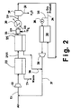
- feed air is separated in a two-stage membrane system to produce a partially purified nitrogen stream that is subject to deoxo treatment to remove residual oxygen therefrom and produce a wet, high purity nitrogen stream.
- the latter is dried in a membrane dryer to produce dry, high purity nitrogen product.
- feed air in line 21 passes through compressor 22 to a first stage membrane 23 from which an oxygen-containing permeate waste stream is separated through line 24.
- the non-permeate gas therefrom passes in line 21A to second stage membrane 25 from which the partially purified nitrogen stream passes in line 26 to deoxo system 27.
- Hydrogen is introduced to deoxo system 27 through line 28 for catalytic reaction with residual oxygen so that a wet, high purity nitrogen stream is removed therefrom in lined 29 containing chiller 30 and phase separator 31 from which condensed water is removed through line 32.
- the saturated high purity nitrogen stream in line 29 is then more fully dried by passage to membrane dryer 33 from which dry, high purity nitrogen product is withdrawn through lined 34.
- a small portion of said dry, high purity nitrogen product is recycled to membrane dryer 33 through lined 35 containing valves 36 for passage therethrough as dry purge in countercurrent flow to the nitrogen gas flow on the feed or non-permeate side of the membrane.
- the purge effluent is discharged from membrane dryer 33 through lined 37 containing vacuum pump 38 for recycle to line 21 for compression and passage to the two-stage membrane system for recovering of additional quantities of nitrogen product.
- the permeate gas from second membrane stage 25 is also desirably passed in line 39 to line 37 for return to the system.
- a membrane dryer stream adapted for the use of purge on the permeate side is employed, said membrane dryer thus being of 4-port design, having feed entry, non-permeate exit, permeate exit and purge entry ports.
- the membrane dryer in each case is a hollow-fiber membrane adapted for countercurrent flow on the permeate and non-permeate sides.
- the membrane has a permeability/thickness ratio on the order of 6.33 x 10 6 Barrer/cm. and a separation factor of water, relative to oxygen, of 1,000. Such values are characteristic of readily achievable state-of-the-art membrane technology.
- the membrane area is set at 13,9 m 2 (150 square feet), and the product flow rate is 0,0283 m 3 /h (1,000 NCFH), with a dewpoint of -40°C (-40°F) at pressure.
- the feed nitrogen to be dried has been produced by an air separation process that removes essentially all of the oxygen, but leaves the nitrogen saturated with water vapor as in the Fig. 2 embodiment.
- the feed nitrogen stream is available at 1137 kPa (150 psig; 165 psia), 37,8°C (100°F) and contains about 5,766 ppm of water vapor.
- the purge ratio, compressor power, vacuum pump power, total power and the product recovery have been determined for various levels of the low, permeate side pressure, Plo, including values at and below atmospheric.
- Plo permeate side pressure
- the results of Table I would appear to indicate that the lower Plo becomes, the greater the overall efficiency that can be obtained in the vacuum purge operation of the invention.
- the range of vacuum pressures suitable for purposes of the invention is generally from about 0,7 to about 52 kPa (about 0.1 to about 7.5 psia), as disclosed above. If the pressure ratio Phi/Plo were to be increased beyond about 100, the amount of purge gas employed could be further reduced, but the resulting increase in product recovery would not be substantial. Furthermore, it is desirable to have more than a negligible quantity of purge gas present at the product end of the membrane dryer. Table I shows that the cleaning ratio remains near 2 for the cases tested.
- the minimum Plo that is conveniently achieved is also limited by the vapour pressure of the water, which is nearly 1 psia at 37,8°C (100°F). Furthermore, relatively simple vacuum pumps can be used to achieve the vacuum pressure levels indicated, while more elaborate and costly vacuum pumps would be required to achieve lower vacuum levels.
- Example 2 This example is similar to that of Example 1, but an external source of dry air is employed for purge purposes, with the other conditions remaining the same as in Example 1.
- Table II Parameter Standard Process Vacuum Process kPa (psia) kPa (psia) Phi (psia) 1137 165 1137 165 Plo (psia) 103 15 13,8 2 Phi/Plo 11 82.5 Purge Ratio % 20.4 2.57 Cleaning Ratio 2.24 2.12 Vacuum Pump Power (W) 0 100 0 2 Conc. (ppm) by back perm. 196 26
- the vacuum purge process of the invention utilizes only 13% of the dry air requirements of conventional practice using purge air available at about atmospheric pressure.
- Example 2 If the amount of oxygen back permeation, i.e. 26 ppm in the Example 2 embodiment of the invention, is still more than is allowed by applicable product specifications, then either product purging must be employed, as in Example 1, or much lower levels of vacuum would be needed if membrane drying operations are to be employed. As suggested above, the costs associated with such very deep levels of vacuum may make such an approach infeasible from a practical operating viewpoint.
- This example pertains to the production of dry air from the ambient atmosphere in a stand-alone process employing product purging.
- the membrane characteristics and the compressor and vacuum pump efficiencies are the same as those pertaining in Examples 1 and 2 above.
- the production requirement of this example is dry air product at a flow rate of 0,0283 m 3 /h (1,000 NCFH) at 275 kPa (40 psia, 25 psig).
- the product dew point is -40°C (-40°F), which is equivalent to 127 ppm.
- the membrane surface area available is 51 m 2 (550 sq. ft.), and the feed air is saturated with water at 37,8°C (100°F) at the feed pressure specified.
- Table III Parameter Case A Lo Pressure Superatmos.
- Case B Hi Pressure Superatmos.
- Case C Vacuum Transatmos. Feed H 2 0 (ppm) 23740 6330 23740 Feed Pressure kPa (psia) kPa (psia) kPa (psia) Phi (psia) 275 40 1034 150 275 40 Plo (psia) 103 15 103 15 27,5 4 Phi/Plo 2.67 10 10 Purge Ratio % 85 10 20 Cleaning Ratio 2.27 1 2 Total Compressor Power (kW) 7.80 3.33 1.46 Vacuum Pump Power (kW) 0 0 0.57 Total Power (kW) 7.80 3.33 2.03
- Case A the feed gas is elevated to the pressure required for the product specifications, and the waste is discharged at atmospheric pressure. This constitutes a simple processing operation, but it uses a high purge ratio relative to feed air flow and has a high feed compressor energy requirement.
- this compressor energy is reduced by increasing the feed gas pressure to 1034 kPa (10 atmospheres; 150 psia).
- the dry air product is also delivered at this pressure, which is higher than that required and, therefore, contains excess unused energy.
- the allocated membrane surface area will permeate all of the moisture required to be removed, even when the cleaning ratio is reduced to a nominal value of one. In practice, it would likely be desirable to employ a smaller membrane area and a higher cleaning ratio under such circumstances.
- Case C represents a desirable embodiment of the transatmospheric process of the invention, wherein the feed gas is compressed to the pressure required for the non-permeate, dry product gas, and the low pressure, permeate side of the membrane is under vacuum at a pressure of 27,5 kPa (4 psia).
- this process requires energy for both compression and vacuum pumping, it will be appreciated that it is more energy efficient than either Case A or Case B. Furthermore, the increased energy efficiency is sufficient to justify the additional cost of the vacuum pump required for the vacuum pumping operation of the invention.
- the membrane composition used in the membrane dryer of the invention should, as indicated above, be one having a high selectivity for water over the gas being dried, i.e. nitrogen and oxygen in air drying. That is moisture must be permeated much more rapidly than air or other gas being dried.
- the water/air separation factor should be at least 50, preferably greater than 1,000, for advantageous moisture removal from feed air.
- the membrane composition should have a relatively low permeability rate for the gas being dried, e.g. for both nitrogen and oxygen in air drying applications.
- Cellulose acetate is an example of a membrane material satisfying such criteria.
- a variety of other membrane materials can also be employed, such as ethyl cellulose, polyurethane, polyamide, polystyrene and the like.
- the passage of the feed air or other gas being dried may be inside-out, wherein the feed gas is passed through the bores of the hollow fibers, or outside-in, wherein the feed gas is passed to the outer or shell side of the membrane bundles with permeate gas being recovered from within the bores of the hollow fibers.
- countercurrent flow patterns can be created by encasing the hollow fiber bundle with an impervious barrier over its longitudinal outer surface except for a non-encased circumferential region conveniently located near one end of the bundle.
- This or other such means serve to enable the feed gas or permeate gas, depending on the desired manner of operation, i.e. inside-out or outside-in to pass in countercurrent flow outside the hollow fibers parallel to the flow direction of permeate gas or feed gas in the bores of the hollow fibers.
- the feed gas on the outside of the hollow fiber bundle for example, is caused to flow parallel to, rather than at right angle to, the central axis of the fiber bundle.
- the membrane fibers may be organized either in straight assemblies parallel to the central axis of the bundle, or alternatively, and preferably, can be wound in helical fashion around the central axis.
- the impermeable barrier may be a wrap of impervious film, e.g. polyvinylidene or the like.
- the impermeable barrier may be an impervious coating material, e.g. polysiloxane, applied from an innocuous solvent, or a shrink sleeve installed over the membrane bundle and shrunk onto said bundle.
- the impermeable barrier thus encases the hollow fiber or other membrane bundle and, as disclosed in said publication, has an opening therein permitting the flow of gas into or from the bundle so that the fluid flows in a direction substantially parallel to the axis of the fiber bundle.
- the flow pattern should be one of countercurrent flow of the wet feed air or other gas stream relative to the permeate gas comprising purge gas supplied as indicated above, together with the moisture that permeates through the membrane material.
- asymmetric or composite membranes are preferred because of their very thin membrane separation regions or layers supported by more porous substrates for mechanical strength and support.
- Dense fiber membranes can also be used, although they have very low permeability rates because of the inherently greater separation region thickness thereof.
- the invention has been described above particularly with respect to the highly desirable gas drying application thereof, it will be understood that the invention can also be practiced with respect to other commercially important gas separations.
- the invention can be used for applications in which it is desired to remove fast permeating components, other than water, from a feed gas stream, e.g. CO 2 and ammonia cleanup from process gas streams.
- the invention is of significance for air separation applications for the recovery of nitrogen product gas, particularly where the membrane systems employed, e.g. facilitated transport membranes, exhibit an enhanced permeability of the oxygen component of feed air.
- the invention represents a significant advance in the membrane separation art.
- the invention enables highly efficient drying and other gas separation operations to be carried out using desirably small amounts of purge gas, with low overall energy requirements.
Priority Applications (1)
| Application Number | Priority Date | Filing Date | Title |
|---|---|---|---|
| EP95118394A EP0702995B1 (en) | 1991-10-07 | 1992-10-06 | Membrane gas separation |
Applications Claiming Priority (2)
| Application Number | Priority Date | Filing Date | Title |
|---|---|---|---|
| US07/772,340 US5226932A (en) | 1991-10-07 | 1991-10-07 | Enhanced meambrane gas separations |
| US772340 | 1991-10-07 |
Related Child Applications (2)
| Application Number | Title | Priority Date | Filing Date |
|---|---|---|---|
| EP95118394.6 Division-Into | 1992-10-06 | ||
| EP95118394A Division EP0702995B1 (en) | 1991-10-07 | 1992-10-06 | Membrane gas separation |
Publications (2)
| Publication Number | Publication Date |
|---|---|
| EP0537599A1 EP0537599A1 (en) | 1993-04-21 |
| EP0537599B1 true EP0537599B1 (en) | 1997-02-19 |
Family
ID=25094740
Family Applications (2)
| Application Number | Title | Priority Date | Filing Date |
|---|---|---|---|
| EP92117057A Expired - Lifetime EP0537599B1 (en) | 1991-10-07 | 1992-10-06 | Membrane gas separation |
| EP95118394A Expired - Lifetime EP0702995B1 (en) | 1991-10-07 | 1992-10-06 | Membrane gas separation |
Family Applications After (1)
| Application Number | Title | Priority Date | Filing Date |
|---|---|---|---|
| EP95118394A Expired - Lifetime EP0702995B1 (en) | 1991-10-07 | 1992-10-06 | Membrane gas separation |
Country Status (12)
| Country | Link |
|---|---|
| US (1) | US5226932A (es) |
| EP (2) | EP0537599B1 (es) |
| JP (1) | JPH05192530A (es) |
| KR (1) | KR930007495A (es) |
| CN (1) | CN1071347A (es) |
| AT (1) | ATE187352T1 (es) |
| BR (1) | BR9203888A (es) |
| CA (1) | CA2078428A1 (es) |
| DE (2) | DE69230412D1 (es) |
| DK (1) | DK0702995T3 (es) |
| MX (1) | MX9205710A (es) |
| TW (1) | TW203014B (es) |
Families Citing this family (55)
| Publication number | Priority date | Publication date | Assignee | Title |
|---|---|---|---|---|
| US6835523B1 (en) * | 1993-05-09 | 2004-12-28 | Semiconductor Energy Laboratory Co., Ltd. | Apparatus for fabricating coating and method of fabricating the coating |
| FR2710044B1 (fr) * | 1993-09-17 | 1995-10-13 | Air Liquide | Procédé de séparation d'un hydrure gazeux ou d'un mélange d'hydrures gazeux à l'aide d'une membrane. |
| US5383956A (en) * | 1993-10-12 | 1995-01-24 | Praxair Technology, Inc. | Start-up and shut down processes for membrane systems and membrane systems useful for the same |
| CN1120464A (zh) | 1994-07-15 | 1996-04-17 | 普拉塞尔技术有限公司 | 改进的气体预净化法 |
| AU690723B2 (en) * | 1994-09-14 | 1998-04-30 | Bend Research, Inc. | Organic and inorganic vapor permeation by countercurrent condensable sweep |
| US5681433A (en) | 1994-09-14 | 1997-10-28 | Bend Research, Inc. | Membrane dehydration of vaporous feeds by countercurrent condensable sweep |
| US5602382A (en) * | 1994-10-31 | 1997-02-11 | Canada Post Corporation | Mail piece bar code having a data content identifier |
| US5785741A (en) * | 1995-07-17 | 1998-07-28 | L'air Liquide, Societe Anonyme Pour L'etude Et L'exploitation Des Procedes Georges, Claude | Process and system for separation and recovery of perfluorocompound gases |
| US5641337A (en) * | 1995-12-08 | 1997-06-24 | Permea, Inc. | Process for the dehydration of a gas |
| US5709732A (en) * | 1996-04-02 | 1998-01-20 | Praxair Technology, Inc. | Advanced membrane system for separating gaseous mixtures |
| US5669959A (en) * | 1996-05-16 | 1997-09-23 | Uop | Process for safe membrane operation |
| IE80909B1 (en) * | 1996-06-14 | 1999-06-16 | Air Liquide | An improved process and system for separation and recovery of perfluorocompound gases |
| US6059857A (en) * | 1996-08-14 | 2000-05-09 | Bend Research, Inc. | Ultrapurification of organic solvents |
| US5843209C1 (en) * | 1996-08-14 | 2001-05-15 | Bend Res Inc | Vapor permeation system |
| CA2275960A1 (en) * | 1997-01-23 | 1998-07-30 | Gil Dagan | Recovery of perfluorinated compounds and hydrofluorocarbon gases using molecular sieve membranes |
| US6117210A (en) * | 1997-04-29 | 2000-09-12 | Praxair Technology, Inc. | Solid electrolyte systems for producing controlled purity oxygen |
| US5944874A (en) * | 1997-06-23 | 1999-08-31 | Praxair Technology, Inc. | Solid electrolyte ionic conductor systems for the production of high purity nitrogen |
| US5851266A (en) * | 1997-06-23 | 1998-12-22 | Praxair Technology,Inc. | Hybrid solid electrolyte ionic conductor systems for purifying inert gases |
| DE19739144C2 (de) * | 1997-09-06 | 2002-04-18 | Geesthacht Gkss Forschung | Vorrichtung zur Entfernung von Wasserdampf aus unter Druck befindlichen Gasen oder Gasgemischen |
| JP3279231B2 (ja) * | 1997-10-13 | 2002-04-30 | トヨタ自動車株式会社 | ヨウ素ガスの分離方法 |
| US5928409A (en) * | 1997-11-12 | 1999-07-27 | New Jersey Institute Of Technology | Method and apparatus for gas removal by cyclic flow swing membrane permeation |
| US5888265A (en) * | 1997-12-22 | 1999-03-30 | Praxair Technology, Inc. | Air separation float glass system |
| US6042634A (en) * | 1998-04-22 | 2000-03-28 | Bacharach, Inc. | Moisture extractor system for gas sampling |
| US6180168B1 (en) | 1999-02-01 | 2001-01-30 | Air Products And Chemicals, Inc. | Process for the manufacture of a membrane device with internal sweep |
| JP3876561B2 (ja) * | 1999-03-15 | 2007-01-31 | 宇部興産株式会社 | ガス分離膜モジュールおよびガス分離方法 |
| US6491739B1 (en) * | 1999-11-09 | 2002-12-10 | Litton Systems, Inc. | Air separation module using a fast start valve for fast warm up of a permeable membrane air separation module |
| US6478852B1 (en) | 2000-02-18 | 2002-11-12 | Cms Technology Holdings, Inc. | Method of producing nitrogen enriched air |
| JP2001269572A (ja) * | 2000-03-28 | 2001-10-02 | Forestry & Forest Products Research Inst Forestry Agency | 無機質多孔粒体の再生方法及び水の浄化方法並びに水の連続浄化装置 |
| US6273937B1 (en) * | 2000-03-29 | 2001-08-14 | Trans Ionics Corporation | Membrane pervaporation and vapor permeation system |
| US7267804B2 (en) * | 2000-07-07 | 2007-09-11 | Buxbaum Robert E | Membrane reactor for gas extraction |
| JP4810748B2 (ja) * | 2000-08-22 | 2011-11-09 | Nok株式会社 | 除湿システム |
| US6581297B1 (en) | 2000-11-17 | 2003-06-24 | Graham-White Manufacturing Company | Drying apparatus and method |
| US6539728B2 (en) * | 2000-12-04 | 2003-04-01 | Amos Korin | Hybrid heat pump |
| DE60120228T2 (de) * | 2001-03-30 | 2007-03-29 | Trans Ionics Corp., The Woodlands | Verfahren zur pervaporation und dampfpermeation mittels einer membran |
| US6719825B2 (en) | 2002-05-07 | 2004-04-13 | Graham-White Manufacturing Company | Air drying apparatus and method |
| JP2006006989A (ja) * | 2004-06-22 | 2006-01-12 | Anest Iwata Corp | 中空糸膜式エアドライヤ |
| US20070193739A1 (en) * | 2005-02-14 | 2007-08-23 | Smith Kevin W | Scale-inhibited water reduction in solutions and slurries |
| JP4547673B2 (ja) * | 2005-05-11 | 2010-09-22 | Smc株式会社 | 空気圧回路におけるエアドライヤの水分パージ方法及びそのシステム |
| US7497895B2 (en) * | 2005-11-18 | 2009-03-03 | Exxonmobil Research And Engineering Company | Membrane separation process |
| CN100398182C (zh) * | 2005-12-13 | 2008-07-02 | 大连理工大学 | 一种用气体分离膜渗透仪测定气体渗透性参数的方法 |
| WO2007090085A2 (en) * | 2006-02-01 | 2007-08-09 | New York Air Brake Corporation | Air dryer for a brake system |
| US7780768B2 (en) * | 2006-11-28 | 2010-08-24 | Inogen, Inc. | Gas concentrator with improved water rejection capability |
| US20090166171A1 (en) * | 2008-01-02 | 2009-07-02 | Total Separation Solutions Llc | Trifunctional membrane tube arrays |
| US20090260253A1 (en) * | 2008-04-17 | 2009-10-22 | Roberts Keith A | Apparatus and method of drying using a gas separation membrane |
| DE102009054921B4 (de) * | 2009-12-18 | 2020-09-03 | Robert Bosch Gmbh | Verfahren und Vorrichtung zur Minderung der Feuchtigkeit eines Gases in einem Batteriegehäuseinnenraum |
| US20110185891A1 (en) | 2010-02-02 | 2011-08-04 | Generon Igs, Inc. | Sweep gas for membrane-based dehydration modules |
| CN103269766A (zh) * | 2010-11-18 | 2013-08-28 | “盖瑞斯”股份有限公司 | 膜气体分离工厂和用于操作其的方法 |
| JP2014004521A (ja) * | 2012-06-25 | 2014-01-16 | Ube Ind Ltd | 高圧乾燥ガス製造システム |
| JP2014024025A (ja) * | 2012-07-27 | 2014-02-06 | Ube Ind Ltd | 除湿システムおよび乾燥空気の製造方法 |
| NL2009415C2 (en) * | 2012-09-04 | 2014-03-05 | Aquaver B V | Air-conditioning system and use thereof. |
| CN105571272B (zh) * | 2015-12-18 | 2018-01-30 | 山东九章膜技术有限公司 | 一种反渗透膜元件湿膜气体压差除湿机以及除湿工艺 |
| US10561978B2 (en) * | 2017-08-09 | 2020-02-18 | Generon Igs, Inc. | Membrane-based gas separation with retentate sweep |
| US10758862B2 (en) | 2017-09-14 | 2020-09-01 | Perma Pure Llc | Portable sampling system |
| CN109506994B (zh) * | 2017-09-14 | 2022-04-19 | 博纯有限责任公司 | 便携式采样系统及用于便携式采样系统的方法 |
| CN110697655A (zh) * | 2019-10-25 | 2020-01-17 | 昊华化工科技集团股份有限公司 | 一种膜分离浓缩回收氢气的方法及系统装置 |
Family Cites Families (31)
| Publication number | Priority date | Publication date | Assignee | Title |
|---|---|---|---|---|
| IT649908A (es) * | 1960-04-01 | |||
| US3256675A (en) * | 1962-11-30 | 1966-06-21 | Gen Electric | Method and apparatus for gas separation by thin films or membranes |
| US3339341A (en) * | 1965-12-22 | 1967-09-05 | Du Pont | Fluid separation process and apparatus |
| US3455817A (en) * | 1968-07-31 | 1969-07-15 | Abcor Inc | Method of and apparatus for the recovery of fractions from chromatographic fractions |
| US3735558A (en) * | 1971-06-29 | 1973-05-29 | Perma Pure Process Inc | Process for separating fluids and apparatus |
| US3735559A (en) * | 1972-02-02 | 1973-05-29 | Gen Electric | Sulfonated polyxylylene oxide as a permselective membrane for water vapor transport |
| GB1440963A (en) * | 1973-04-30 | 1976-06-30 | Skarstrom C W | Process for separating a component from a fluid mixture |
| JPS6099328A (ja) * | 1983-11-04 | 1985-06-03 | Toyota Central Res & Dev Lab Inc | 凝縮性ガス分離装置 |
| EP0192143B1 (en) * | 1985-02-09 | 1996-01-10 | Asahi Kasei Kogyo Kabushiki Kaisha | Permeable polymer membrane for desiccation of gas |
| ZA865173B (en) * | 1985-07-31 | 1987-03-25 | Celanese Corp | Immobilized liquid membrane |
| EG18145A (en) | 1985-12-10 | 1992-08-30 | Albany Int Corp | Hollow fiber separatory modul with encased fiber bundle |
| US4687578A (en) * | 1985-12-12 | 1987-08-18 | Monsanto Company | Fluid separation membranes |
| EP0263212B1 (en) * | 1986-10-08 | 1990-12-27 | Ube Industries, Ltd. | Method for removing water vapor from water vapor-containing gas |
| JPS63111923A (ja) * | 1986-10-28 | 1988-05-17 | Kuraray Co Ltd | 空気の除湿装置 |
| US4737166A (en) * | 1986-12-30 | 1988-04-12 | Bend Research, Inc. | Acid gas scrubbing by composite solvent-swollen membranes |
| DE3726431A1 (de) * | 1987-08-08 | 1989-02-16 | Daimler Benz Ag | Verfahren zur abtrennung von organischen daempfen aus einem luftstrom |
| JPH0824815B2 (ja) * | 1987-08-21 | 1996-03-13 | 住友精化株式会社 | ガスの分離方法 |
| US4857081A (en) * | 1987-10-15 | 1989-08-15 | Separation Dynamics, Inc. | Separation of water from hydrocarbons and halogenated hydrocarbons |
| US4783201A (en) * | 1987-12-28 | 1988-11-08 | Rice Arthur W | Gas dehydration membrane apparatus |
| FR2625690B1 (fr) * | 1988-01-11 | 1993-04-23 | Inst Francais Du Petrole | Procede de separation des constituants d'un melange en phase gazeuse au moyen d'une membrane composite |
| JPH0270717A (ja) * | 1988-09-07 | 1990-03-09 | Sumitomo Durez Co Ltd | シエルモールド用ノボラック型フェノール樹脂 |
| US4906256A (en) * | 1989-03-23 | 1990-03-06 | Membrane Technology & Research, Inc. | Membrane process for treatment of fluorinated hydrocarbon-laden gas streams |
| US4934148A (en) * | 1989-05-12 | 1990-06-19 | Union Carbide Corporation | Dry, high purity nitrogen production process and system |
| US4931070A (en) * | 1989-05-12 | 1990-06-05 | Union Carbide Corporation | Process and system for the production of dry, high purity nitrogen |
| US5004482A (en) * | 1989-05-12 | 1991-04-02 | Union Carbide Corporation | Production of dry, high purity nitrogen |
| US4950315A (en) * | 1989-07-14 | 1990-08-21 | A/G Technology Corporation | Multiple head pumping |
| US4961759A (en) * | 1989-08-17 | 1990-10-09 | Separation Dynamics, Inc. | Closed loop gas dehydration process and apparatus |
| US5002590A (en) * | 1989-09-19 | 1991-03-26 | Bend Research, Inc. | Countercurrent dehydration by hollow fibers |
| US5034025A (en) * | 1989-12-01 | 1991-07-23 | The Dow Chemical Company | Membrane process for removing water vapor from gas |
| US5067971A (en) * | 1990-02-12 | 1991-11-26 | Union Carbide Industrial Gases Technology Corporation | Process for dehydration of gases and composite permeable membranes therefor |
| US5084073A (en) * | 1990-10-11 | 1992-01-28 | Union Carbide Industrial Gases Technology Corporation | Membrane drying process and system |
-
1991
- 1991-10-07 US US07/772,340 patent/US5226932A/en not_active Expired - Fee Related
-
1992
- 1992-10-06 EP EP92117057A patent/EP0537599B1/en not_active Expired - Lifetime
- 1992-10-06 AT AT95118394T patent/ATE187352T1/de not_active IP Right Cessation
- 1992-10-06 MX MX9205710A patent/MX9205710A/es unknown
- 1992-10-06 CA CA002078428A patent/CA2078428A1/en not_active Abandoned
- 1992-10-06 KR KR1019920018298A patent/KR930007495A/ko active IP Right Grant
- 1992-10-06 DK DK95118394T patent/DK0702995T3/da active
- 1992-10-06 BR BR929203888A patent/BR9203888A/pt not_active IP Right Cessation
- 1992-10-06 EP EP95118394A patent/EP0702995B1/en not_active Expired - Lifetime
- 1992-10-06 DE DE69230412T patent/DE69230412D1/de not_active Expired - Lifetime
- 1992-10-06 CN CN92112084A patent/CN1071347A/zh active Pending
- 1992-10-06 DE DE69217529T patent/DE69217529T2/de not_active Expired - Fee Related
- 1992-10-06 JP JP4290955A patent/JPH05192530A/ja active Pending
- 1992-10-06 TW TW081107929A patent/TW203014B/zh active
Also Published As
| Publication number | Publication date |
|---|---|
| DE69217529T2 (de) | 1997-09-04 |
| DE69217529D1 (de) | 1997-03-27 |
| US5226932A (en) | 1993-07-13 |
| DE69230412D1 (de) | 2000-01-13 |
| KR930007495A (ko) | 1993-05-20 |
| EP0702995B1 (en) | 1999-12-08 |
| CA2078428A1 (en) | 1993-04-08 |
| ATE187352T1 (de) | 1999-12-15 |
| BR9203888A (pt) | 1993-04-27 |
| DK0702995T3 (da) | 2000-05-01 |
| MX9205710A (es) | 1993-05-01 |
| TW203014B (es) | 1993-04-01 |
| EP0702995A1 (en) | 1996-03-27 |
| EP0537599A1 (en) | 1993-04-21 |
| JPH05192530A (ja) | 1993-08-03 |
| CN1071347A (zh) | 1993-04-28 |
Similar Documents
| Publication | Publication Date | Title |
|---|---|---|
| EP0537599B1 (en) | Membrane gas separation | |
| US5205842A (en) | Two stage membrane dryer | |
| US5004482A (en) | Production of dry, high purity nitrogen | |
| EP0547387B1 (en) | Membrane air drying and separation operations | |
| US4931070A (en) | Process and system for the production of dry, high purity nitrogen | |
| EP0397192B1 (en) | Dry, high purity nitrogen production process and apparatus | |
| US5116396A (en) | Hybrid prepurifier for cryogenic air separation plants | |
| US5259869A (en) | Use of membrane separation to dry gas streams containing water vapor | |
| EP0490322B1 (en) | Three-stage membrane gas separation process and system | |
| EP0430304B1 (en) | Separation of gas mixtures | |
| CA2111923A1 (en) | High purity membrane nitrogen | |
| EP0695574B1 (en) | Gas separation with fractional purge for pre- or post-purification | |
| EP0692297A2 (en) | Gas prepurification | |
| EP0613857A1 (en) | Purification of crude argon |
Legal Events
| Date | Code | Title | Description |
|---|---|---|---|
| PUAI | Public reference made under article 153(3) epc to a published international application that has entered the european phase |
Free format text: ORIGINAL CODE: 0009012 |
|
| AK | Designated contracting states |
Kind code of ref document: A1 Designated state(s): AT BE CH DE DK ES FR GB GR IT LI LU NL SE |
|
| 17P | Request for examination filed |
Effective date: 19930504 |
|
| 17Q | First examination report despatched |
Effective date: 19940725 |
|
| GRAG | Despatch of communication of intention to grant |
Free format text: ORIGINAL CODE: EPIDOS AGRA |
|
| GRAH | Despatch of communication of intention to grant a patent |
Free format text: ORIGINAL CODE: EPIDOS IGRA |
|
| RBV | Designated contracting states (corrected) | ||
| GRAH | Despatch of communication of intention to grant a patent |
Free format text: ORIGINAL CODE: EPIDOS IGRA |
|
| GRAA | (expected) grant |
Free format text: ORIGINAL CODE: 0009210 |
|
| ITF | It: translation for a ep patent filed |
Owner name: BARZANO' E ZANARDO ROMA S.P.A. |
|
| AK | Designated contracting states |
Kind code of ref document: B1 Designated state(s): DE FR IT |
|
| XX | Miscellaneous (additional remarks) |
Free format text: TEILANMELDUNG 95118394.6 EINGEREICHT AM 22/11/95. |
|
| REF | Corresponds to: |
Ref document number: 69217529 Country of ref document: DE Date of ref document: 19970327 |
|
| ET | Fr: translation filed | ||
| PLBE | No opposition filed within time limit |
Free format text: ORIGINAL CODE: 0009261 |
|
| STAA | Information on the status of an ep patent application or granted ep patent |
Free format text: STATUS: NO OPPOSITION FILED WITHIN TIME LIMIT |
|
| 26N | No opposition filed | ||
| PGFP | Annual fee paid to national office [announced via postgrant information from national office to epo] |
Ref country code: FR Payment date: 19980917 Year of fee payment: 7 |
|
| PGFP | Annual fee paid to national office [announced via postgrant information from national office to epo] |
Ref country code: DE Payment date: 19980921 Year of fee payment: 7 |
|
| PG25 | Lapsed in a contracting state [announced via postgrant information from national office to epo] |
Ref country code: FR Free format text: LAPSE BECAUSE OF NON-PAYMENT OF DUE FEES Effective date: 20000630 |
|
| PG25 | Lapsed in a contracting state [announced via postgrant information from national office to epo] |
Ref country code: DE Free format text: LAPSE BECAUSE OF NON-PAYMENT OF DUE FEES Effective date: 20000801 |
|
| REG | Reference to a national code |
Ref country code: FR Ref legal event code: ST |
|
| PG25 | Lapsed in a contracting state [announced via postgrant information from national office to epo] |
Ref country code: IT Free format text: LAPSE BECAUSE OF NON-PAYMENT OF DUE FEES;WARNING: LAPSES OF ITALIAN PATENTS WITH EFFECTIVE DATE BEFORE 2007 MAY HAVE OCCURRED AT ANY TIME BEFORE 2007. THE CORRECT EFFECTIVE DATE MAY BE DIFFERENT FROM THE ONE RECORDED. Effective date: 20051006 |