EP0534805B1 - Klimagerät - Google Patents
Klimagerät Download PDFInfo
- Publication number
- EP0534805B1 EP0534805B1 EP92308841A EP92308841A EP0534805B1 EP 0534805 B1 EP0534805 B1 EP 0534805B1 EP 92308841 A EP92308841 A EP 92308841A EP 92308841 A EP92308841 A EP 92308841A EP 0534805 B1 EP0534805 B1 EP 0534805B1
- Authority
- EP
- European Patent Office
- Prior art keywords
- screen
- evaporator
- condenser
- air conditioner
- disposed
- Prior art date
- Legal status (The legal status is an assumption and is not a legal conclusion. Google has not performed a legal analysis and makes no representation as to the accuracy of the status listed.)
- Expired - Lifetime
Links
Images


Classifications
-
- F—MECHANICAL ENGINEERING; LIGHTING; HEATING; WEAPONS; BLASTING
- F24—HEATING; RANGES; VENTILATING
- F24F—AIR-CONDITIONING; AIR-HUMIDIFICATION; VENTILATION; USE OF AIR CURRENTS FOR SCREENING
- F24F13/00—Details common to, or for air-conditioning, air-humidification, ventilation or use of air currents for screening
- F24F13/20—Casings or covers
-
- F—MECHANICAL ENGINEERING; LIGHTING; HEATING; WEAPONS; BLASTING
- F24—HEATING; RANGES; VENTILATING
- F24F—AIR-CONDITIONING; AIR-HUMIDIFICATION; VENTILATION; USE OF AIR CURRENTS FOR SCREENING
- F24F1/00—Room units for air-conditioning, e.g. separate or self-contained units or units receiving primary air from a central station
- F24F1/02—Self-contained room units for air-conditioning, i.e. with all apparatus for treatment installed in a common casing
- F24F1/022—Self-contained room units for air-conditioning, i.e. with all apparatus for treatment installed in a common casing comprising a compressor cycle
- F24F1/027—Self-contained room units for air-conditioning, i.e. with all apparatus for treatment installed in a common casing comprising a compressor cycle mounted in wall openings, e.g. in windows
Definitions
- the present invention relates to air conditioners.
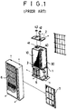
- FIG. 1 of the accompanying diagrammatic drawings illustrates a conventional air conditioner with an evaporator 10, a condenser 30 facing one face of the evaporator, an integral stationary casing 1 disposed longitudinally between the evaporator and the condenser, and cross fans 40,41 for guiding air flow toward the evaporator 10 and the condenser 30 respectively.
- respective upper and lower frames 2,3 are located at respective upper and lower ends of the casing 1.
- Under the lower frame 3 are disposed fan motors (not shown) which are connected to the cross fans, respectively.
- a compressor 5 for compressing and discharging a refrigerant.
- On the upper frame 2 are engaged supporting members 42,43 which support the upper shafts of the cross fans, respectively. Cooling air is discharged through a grill 6.
- a filter 7 removes dust from the air flow.
- Patent Abstracts of Japan vol. 007, no. 031 (M-192) (8 Feb 1993) discloses an air conditioner comprising a frame holding a condenser beneath an evaporator with two fans, each of which is driven by its own motor. This air conditioner is larger than is desirable and does not simply allow an effective method of changing from a heating to a cooling function.
- the air conditioner comprises a casing located in a place where indoor air intakes through a front portion and discharges through the same portion, and a casing located in a place where outdoor air is taken in though a rear portion and discharged through the same portion.
- Heat exchangers are stacked intersectedly and cross fans are coaxially disposed one above the other. Between the upper cross fan and the lower cross fan is placed a transmission for rotating the cross fans reversibly.
- a fan motor is placed at one end of the fans and at the opposite end of the transmission.
- This arrangement reduces the size of the air conditioner.
- the air conditioner requires an additional changeover device for reversing the flow of the refrigerant in order to heat as well as cool the air flowing through it. Furthermore, the condensate generated by the evaporator drops down onto an intermediate platform and drains out through a drain passage formed in the platform without any further use to the air conditioner, which decreases the efficiency of the air conditioner.
- Preferred embodiments of the present invention seek to provide an air conditioner which easily and effectively solves the above mentioned problems.
- An aim of preferred embodiments of the present invention is to provide an air conditioner in which both cooling and heating are achieved in one system without reversing the flow of the refrigerant in the system.
- Another aim is to provide an air conditioner in which condensate formed in an evaporator drops down to a condenser so as to increase heat loss therefrom.
- an air conditioner comprising:
- said frame comprises an intermediate platform for separating said evaporator and said condenser, an upper platform formed over the upper part of said evaporator, a lower platform formed under the lower part of said condenser, a rail formed in each platform for guiding movement of said screen, and a groove formed in each platform for restricting the movement of said evaporator and said condenser.
- said screen members comprise an upper screen member arranged movably back and forth between the front face of said evaporator and the rear face thereof and a lower screen member arranged movably back and forth between the front face of said condenser and the rear face thereof.
- said upper screen member and said lower screen member respectively comprise a screen, a pair of vertical rods for fixing respectively both vertical ends of said screen, a pair of horizontal flexible rods encompassing respectively upper and lower horizontal portions of said screen, a plurality of supporting rods disposed in said screen for reinforcing said screen, and a plurality of actuators connected to said control means for moving respectively said screen members between the front face of said evaporator and the rear face thereof and between the front face of said condenser and the rear face thereof.
- a travelling member in said control means comprises an upper travelling shaft connected to said evaporator, a lower travelling shaft connected to said condenser, and a stepping motor for operating simultaneously said upper travelling shaft and said lower travelling shaft in a reverse manner.
- a swing member in said control means comprises an upper swing shaft disposed at an end of said evaporator, a lower swing shaft disposed at an end of said condenser, and a stepping motor for operating simultaneously said upper swing shaft and said lower swing shaft in a reverse manner.
- said upper screen is disposed adjacent the rear face of said evaporator, and said lower screen is disposed adjacent the front face of said condenser when in a cooling mode, while said upper screen is disposed adjacent the front face of said evaporator, and said lower screen is disposed adjacent the rear face of said condenser when in a heating mode.
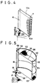
- FIGS. 2 to 6 illustrate an air conditioner in accordance with a preferred embodiment of the present invention.
- the air conditioner includes an evaporator 10 and a condenser 30 which are pivotally mounted by a control means 90 with the evaporator 10 arranged over the condenser 30. Between the evaporator 10 and the condenser 30 are disposed intermediate platform members 50 which comprise a lower intermediate platform 52 and a upper intermediate platform 51. An upper platform 70 is disposed over the evaporator 10, and a lower platform 80 is disposed beneath the condenser 30. Screen members 100, 200 comprise an upper screen member 100 for the evaporator 10 and a lower screen member 200 for the condenser 30.
- the screen members 100,200 are arranged so as to travel back and forth between the front face of the evaporator 10 and the rear face of the condenser 30 or between the front face of the condenser 30 and the rear face of the evaporator 10.
- the control member 90 for pivoting the evaporator 10 and the condenser 30 and moving the screen members 100, 200.
- a fan motor 44 for rotating cross-fans 40, 41 which forcibly move outdoor and indoor air.
- a respective rail 53 is formed for guiding travel of the screen members 100,200, respectively.
- the configuration of the rail 53 comprises a straight line adjacent a front edge of the upper and lower intermediate platforms 51,52 and a curved line extending from the forward end of the straight line as illustrated at Figure 3.
- the curved line runs toward a rear edge of the upper and lower intermediate platforms 51,52 and turns to near a starting point of the straight line as illustrated at Figure 3.
- a respective groove 54 is formed for guiding the travel of roller bearings 11 which are engaged in the upper end edge 10A and a lower end edge 10B of the evaporator and at similar positions in the condenser 30, not shown.
- a rail 53 and a groove 54 are formed, respectively, having the same configuration as above.
- an upper drain duct 55 between the rail 53 and the groove 54 for gathering condensate from the evaporator 10.
- the upper drain duct 55 has an upper drain passage 56 which is at a lower level of the drain duct 55.
- a lower drain duct 57 for collecting the condensate therefrom.
- a plurality of openings 58 are formed for dropping the condensate down to the condenser 30.
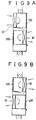
- the control member 90 includes a pivot member for moving both the evaporator 10 and the condenser 30 within a predetermined range, and a travelling member for pivoting screen members 100,200 back and forth.
- the pivot member comprises a stepping motor 91 which swings both the evaporator 10 and the condenser 30 within the range of the groove 54.
- the pivot member also comprises an upper pivot shaft 92 vertically secured to the evaporator 10.
- the pivot member also consists of a lower pivot shaft 93 vertically secured to the condenser 30.
- One end of the lower pivot shaft 93 is mounted to the lower platform 80 and the other end thereof includes a driven gear 93A which is in mechanical communication with the driving gear 92A of the upper pivot shaft 92.
- the evaporator 10 and the condenser 30 are positioned in a manner so as to pivot in opposite directions relative to each other.
- the travelling member comprises a stepping motor 95 which moves screen members 100,200 between the surfaces of the evaporator 10 and those of the condenser 30 back and forth.
- the stepping motor 95 is disposed near the stepping motor 91 of the pivot member.
- the travelling member also consists of an upper travelling shaft 96 connected to an upper screen member 100.
- One end of the upper travelling shaft 96 is pivotally mounted to the upper platform 70 and the other end thereof is connected so as to be in mechanical communication with the stepping motor 95 and extends further downwardly through the stepping motor 95 which further includes a driving gear 96A.
- the travelling member also consists of a lower travelling shaft 97 connected to a lower screen member 200.
- One end of the lower travelling shaft 97 is pivotally mounted to the lower platform 80 and the other end thereof extends upwardly with a driven gear 97A formed thereon so as to mechanically communicate with the driving gear 96A.
- the upper travelling shaft 96 and the lower travelling shaft 97 rotate in a reverse manner.
- the upper screen member is aligned adjacent to the front surface of the evaporator 10
- the lower screen member is aligned adjacent to the rear surface of the condenser 30.
- the upper screen member is aligned vice versa
- the lower screen member is aligned vice versa.
- the upper screen member 100 and the lower screen member 200 each consist of a screen 101 which has a characteristic of heat insulation.
- a pair of vertical rods 102 are fixed respectively to both vertical ends of the screen 101.
- a pair of horizontal flexible rods 103 are encompassed respectively through each upper and lower horizontal end of the screen 101 to permit the screen 101 to travel along the rail 53.
- the horizontal rod 103 is elastic to help the screen member 100 to travel in a retro or backward position.
- a plurality of supporting rods 104 are disposed in the screen 101 for reinforcing the screen 101.
- Each of the vertical rods 102 has rings 105 at the upper portion of the vertical rod 102 and the lower portion thereof, respectively.
- One end of a string 106 is tied to the ring 105 at the upper portion of the right hand vertical rod 102, and other end of a string 106 is tied to the ring 105 at a corresponding portion of the left hand vertical rod 102, as illustrated in Figure 5.
- another string is tied to the vertical rod as above.
- the string is wound up on the upper travelling shaft 96 so that when the left hand vertical rod 102 of the screen member 100 approaches toward the travelling shaft 96, the right hand vertical rod 102 is retracted away from the travelling shaft 96, and vice versa.
- the string 106 is wound up on the lower travelling shaft 97 in the reverse manner in respect to the travelling direction of the vertical rod 102.
- the lower screen 200 is placed adjacent to the front surface of the condenser 30.
- the upper screen 100 is placed adjacent to the front surface of the evaporator 10
- the lower screen 200 is placed adjacent to the rear surface of the condenser 30.
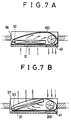
- the evaporator 10 is aligned adjacent to the indoor area as shown in Figure 7A.
- the upper screen 100 moves along the rail 53 and is disposed adjacent to the outdoors.
- the indoor air is taken into the air conditioner through the grill by the rotation of the cross fan 40.
- the flow of the air is guided by the screen 100 and is discharged back to the indoors through the cross fan 40.
- the condenser 30 is aligned adjacent to the outdoors.
- the lower screen 200 moves along the rail 53 and is disposed adjacent to the indoors.
- the outdoor air is taken into the air conditioner through the back grill by the rotation of the cross fan 41 and heat exchanges with the condenser 30.
- the flow of the air is guided by the screen 200 and is discharged back to the outdoors through the cross fan 41. Therefore, the air indoors becomes cool.
- the condensate generated from the surface of the evaporator 10 drops down to the condenser 30 through the openings 58 formed in the intermediate platforms 50.
- the condensate increase the heat loss from the condenser 30 so as to increase the efficiency of the air conditioner.
- the evaporator 10 is moved adjacent to the outdoors along the groove 54 about the upper pivot shaft 92 in a counter-clock direction.
- the upper screen 100 moves along the rail 53 in a clockwise direction by the same directional rotation of the travelling shaft 96.
- the upper screen 100 is disposed adjacent to the indoors.
- the outdoor air is taken into the air conditioner through the back grill by the rotation of the cross fan 40 and heat exchanges with the evaporator 10.
- the flow of the air is guided by the screen 100 and is discharged back to the outdoors through the cross fan 40.
- the heating and cooling are achieved in one system without reversing the flow of the refrigerant in the system. Further, the condensate of the evaporator is used to increase the efficiency of the cooling mode.
Claims (7)
- Ein Klimagerät mit:einem Gestell,einem Verdampfer (10), der im Gestell angeordnet ist,einem Kondensator (30), der im Gestell unterhalb des Verdampfers angeordnet ist,einem Paar Lüfter (40, 41), die im Gestell zum zwangsweise Bewegen der Luft angeordnet sind, undeinem Lüftermotor, der mit jedem Lüfter (40, 41) betrieblich verbunden ist, um die Lüfter (40, 41) zu drehen,dadurch gekennzeichnet, daß:der Verdampfer und der Kondensator schwenkbar im Gestell angeordnet sind;ein Paar Blendenelemente (100, 200) beweglich zwischen einer Vorderseite und einer Rückseite des Verdampfers (10) bzw. zwischen einer Vorderseite und einer Rückseite des Kondensators (30) zum Führen eines Luftstromes angeordnet ist, wobei die Blendenelemente (100, 200) eine obere Blende (100) für den Verdampfer (10) und eine untere Blende (200) für den Kondensator (30) aufweisen; undSteuereinrichtungen vorgesehen sind, um den Verdampfer (10) und den Kondensator (30) innerhalb eines festgeleten Bereiches zu schwenken und um die Blendenelemente (100, 200) gleichzeitig in entgegengesetzte Richtungen zu schieben.
- Ein Klimagerät gemäß Anspruch 1, bei dem das Gestell aufweist eine Zwischenplattform (50) zum Trennen des Verdampfers (10) und des Kondensators (30), eine obere Plattform (70), die über dem oberen Teil des Verdampfers (10) ausgebildet ist, eine untere Plattform (80), die unter dem unteren Teil des Kondensators (30) ausgebildet ist, eine Schiene (53), die in jeder Plattform (50, 70, 80) zum Führen der Bewegung der Blende (100, 200) ausgebildet ist, und eine Nut (54), die in jeder Plattform (50, 70, 80) ausgebildet ist, um die Bewegung des Verdampfers (10) und des Kondensators (30) zu beschränken.
- Ein Klimagerät gemäß Anspruch 1 oder 2, bei dem die Blendenelemente (100, 200) ein oberes Blendenelement (100) aufweisen, das zwischen der Vorderseite und der Rückseite des Verdampfers (10) zurück- und vorbewegbar angeordnet ist, und ein unteres Blendenelement (200) aufweisen, das zwischen der Vorderseite und der Rückseite des Kondensators (30) zurück- und vorbewegbar angeordnet ist.
- Ein Klimagerät gemäß Anspruch 3, bei dem das obere Blendenelement (100) bzw. das untere Blendenelement (200) aufweist eine Blende (101), ein Paar vertikale Stäbe (102) zum entsprechenden Befestigen beider vertikaler Enden der Blende (101), ein Paar horizontale, flexible Stäbe (103), die einen oberen bzw. einen unteren horizontalen Abschnitt der Blende (101) umfassen, eine Vielzahl von Stützstäben (104), die in der Blende (101) zum Versteifen der Blende (101) angeordnet sind, und eine Vielzahl von Stellgliedern (95), die mit den Steuereinrichtungen (90) zum Bewegen der Blendenelemente (100, 200) zwischen der Vorderseite und der Rückseite des Verdampfers (10) bzw. zwischen der Vorderseite und der Rückseite des Kondensators (30) verbunden sind.
- Ein Klimagerät gemäß Anspruch 4, bei dem ein Verschiebeelement in den Steuereinrichtungen (90) eine obere Verschiebewelle (96), die mit dem Verdampfer (10) verbunden ist, eine untere Verschiebewelle (97), die mit dem Kondensator (30) verbunden ist, und einen Schrittmotor (91) zum gleichzeitigen Betätigen der oberen Verschiebewelle (96) und der unteren Verschiebewelle (97) auf entgegengesetzte Weise aufweist.
- Ein Klimagerät gemäß einem der vorhergehenden Ansprüche, bei dem ein Schwenkelement in den Steuereinrichtungen (90) eine obere Schwenkwelle (96), die an einem Ende des Verdampfers (10) angeordnet ist, eine untere Schwenkwelle (97), die an einem Ende des Kondensators (30) angeordnet ist, und einen Schrittmotor (95) zum gleichzeitigen Betätigen der oberen Schwenkwelle (96) und der unteren Schwenkwelle (97) auf entgegengesetzte Weise aufweist.
- Ein Klimagerät gemäß Anspruch 1, bei dem in einem Kühlmodus die obere Blende (100) angrenzend an die Rückseite des Verdampfers (10) angeordnet ist und die untere Blende (200) angrenzend an die Vorderseite des Kondensators (30) angeordnet ist, während in einem Heizmodus die obere Blende (100) angrenzend an die Vorderseite des Verdampfers (10) angeordnet ist und die untere Blende (200) angrenzend an die Rückseite des Kondensators (30) angeordnet ist.
Applications Claiming Priority (4)
| Application Number | Priority Date | Filing Date | Title |
|---|---|---|---|
| KR1683191 | 1991-09-27 | ||
| KR1019910016831A KR940004107B1 (ko) | 1991-09-27 | 1991-09-27 | 공기조화기의 냉,난방전환장치 및 방법 |
| KR1782691 | 1991-10-24 | ||
| KR910017826 | 1991-10-24 |
Publications (3)
| Publication Number | Publication Date |
|---|---|
| EP0534805A2 EP0534805A2 (de) | 1993-03-31 |
| EP0534805A3 EP0534805A3 (en) | 1993-10-27 |
| EP0534805B1 true EP0534805B1 (de) | 1996-08-21 |
Family
ID=26628756
Family Applications (1)
| Application Number | Title | Priority Date | Filing Date |
|---|---|---|---|
| EP92308841A Expired - Lifetime EP0534805B1 (de) | 1991-09-27 | 1992-09-28 | Klimagerät |
Country Status (5)
| Country | Link |
|---|---|
| US (1) | US5255532A (de) |
| EP (1) | EP0534805B1 (de) |
| JP (1) | JPH07104010B2 (de) |
| DE (1) | DE69212937T2 (de) |
| TW (1) | TW197492B (de) |
Cited By (3)
| Publication number | Priority date | Publication date | Assignee | Title |
|---|---|---|---|---|
| WO2004088209A1 (en) * | 2003-04-03 | 2004-10-14 | Air-Aroz Pty Ltd | Means and method of providing localised cooling |
| CN1755274B (zh) * | 2004-09-29 | 2010-05-05 | 乐金电子(天津)电器有限公司 | 一体式空调器的百叶窗式格栅窗 |
| CN1755224B (zh) * | 2004-09-29 | 2010-05-05 | 乐金电子(天津)电器有限公司 | 一体式空调器的百叶窗式格栅窗 |
Families Citing this family (13)
| Publication number | Priority date | Publication date | Assignee | Title |
|---|---|---|---|---|
| US5533357A (en) * | 1995-02-15 | 1996-07-09 | Carrier Corporation | Air conditioning apparatus |
| DE10353046A1 (de) * | 2003-11-13 | 2005-06-09 | Lessing, Jürgen | Kühlvorrichtung, insbesondere zum Kühlen von Kühlräumen |
| ES2226593B1 (es) * | 2004-11-19 | 2006-04-16 | Bsh Electrodomesticos España, S.A. | Equipo de aire acondicionado movil. |
| US7752863B2 (en) * | 2006-07-03 | 2010-07-13 | Lg Electronics Inc. | Air conditioner |
| ITBO20110687A1 (it) * | 2011-12-02 | 2013-06-03 | Giuliano Ungarelli | Condizionatore a recupero d'acqua di condensazione e calore |
| US9157670B2 (en) | 2013-10-25 | 2015-10-13 | Kooltronic, Inc. | Hazardous location heat transfer unit |
| JP6388734B2 (ja) * | 2015-12-18 | 2018-09-12 | 三菱電機株式会社 | 冷凍サイクル装置の室外機 |
| US11085653B2 (en) | 2016-10-16 | 2021-08-10 | Premium Home Comfort, Inc. | Air conditioner and an air conditioner housing |
| CN108917025A (zh) * | 2018-08-20 | 2018-11-30 | 珠海格力电器股份有限公司 | 移动空调 |
| US11859856B1 (en) * | 2019-01-04 | 2024-01-02 | Renu, Inc. | HVAC system with single piece body |
| KR102565503B1 (ko) * | 2019-01-29 | 2023-08-11 | 삼성전자주식회사 | 공기조화기 |
| CN210921603U (zh) | 2019-11-29 | 2020-07-03 | 广东美的制冷设备有限公司 | 整体式空调 |
| CN111059708A (zh) * | 2019-12-06 | 2020-04-24 | 珠海格力电器股份有限公司 | 一种带有旋转显示器的空调器 |
Family Cites Families (6)
| Publication number | Priority date | Publication date | Assignee | Title |
|---|---|---|---|---|
| US3084522A (en) * | 1960-06-01 | 1963-04-09 | Whirlpool Co | Reverse air cycle air conditioner |
| DE1454612C3 (de) * | 1964-12-09 | 1974-11-07 | Nikolaus 7141 Aldingen Laing | Wärmepumpe mit zwei Wärmetauschern und diesen zugeordneten Querstromgebläsen |
| US4297855A (en) * | 1980-05-21 | 1981-11-03 | General Electric Company | Air valve heat pump |
| US4359876A (en) * | 1981-02-17 | 1982-11-23 | General Electric Company | Room air conditioner sensor application |
| JPS57184843A (en) * | 1981-05-08 | 1982-11-13 | Susumu Kuniya | Air-conditioner with switching dumper |
| JPS6139233A (ja) * | 1984-07-27 | 1986-02-25 | Matsushita Electric Ind Co Ltd | 金属薄膜型磁気記録媒体の製造法 |
-
1992
- 1992-09-26 TW TW081107646A patent/TW197492B/zh active
- 1992-09-28 DE DE69212937T patent/DE69212937T2/de not_active Expired - Fee Related
- 1992-09-28 EP EP92308841A patent/EP0534805B1/de not_active Expired - Lifetime
- 1992-09-28 US US07/951,754 patent/US5255532A/en not_active Expired - Fee Related
- 1992-09-28 JP JP4258060A patent/JPH07104010B2/ja not_active Expired - Lifetime
Cited By (3)
| Publication number | Priority date | Publication date | Assignee | Title |
|---|---|---|---|---|
| WO2004088209A1 (en) * | 2003-04-03 | 2004-10-14 | Air-Aroz Pty Ltd | Means and method of providing localised cooling |
| CN1755274B (zh) * | 2004-09-29 | 2010-05-05 | 乐金电子(天津)电器有限公司 | 一体式空调器的百叶窗式格栅窗 |
| CN1755224B (zh) * | 2004-09-29 | 2010-05-05 | 乐金电子(天津)电器有限公司 | 一体式空调器的百叶窗式格栅窗 |
Also Published As
| Publication number | Publication date |
|---|---|
| TW197492B (de) | 1993-01-01 |
| JPH05203189A (ja) | 1993-08-10 |
| EP0534805A3 (en) | 1993-10-27 |
| US5255532A (en) | 1993-10-26 |
| JPH07104010B2 (ja) | 1995-11-08 |
| DE69212937T2 (de) | 1997-02-27 |
| EP0534805A2 (de) | 1993-03-31 |
| DE69212937D1 (de) | 1996-09-26 |
Similar Documents
| Publication | Publication Date | Title |
|---|---|---|
| EP0534805B1 (de) | Klimagerät | |
| CA2409963C (en) | Hybrid window/split air treatment appliance | |
| KR101781845B1 (ko) | 공기조화장치의 실내기 | |
| CN100451475C (zh) | 空调器 | |
| JP2004012060A (ja) | 空気調和機の室内ユニット及び空気調和機 | |
| US5094089A (en) | Driving system for dual tangential blowers in an air conditioner | |
| JP2902606B2 (ja) | 空気調和機の吸入グリルの開閉装置 | |
| JP3293976B2 (ja) | 空気調和機の風向変更装置 | |
| JPH08178338A (ja) | 空気調和装置の室内機 | |
| CA2031425A1 (en) | Air conditioner with dual cross flow blowers | |
| CN100362288C (zh) | 空调出风口结构 | |
| JP4752142B2 (ja) | 空気調和機用室内機 | |
| KR200202068Y1 (ko) | 공기조화기 | |
| KR20090008629A (ko) | 공기조화기 | |
| JP3947804B2 (ja) | 空気調和機 | |
| JPH0742046Y2 (ja) | 空気調和機 | |
| KR940004107B1 (ko) | 공기조화기의 냉,난방전환장치 및 방법 | |
| CN212987426U (zh) | 一种可调节出风口的空调室内机及空调系统 | |
| KR100236342B1 (ko) | 컨버터블형 공기조화기 | |
| KR930004184Y1 (ko) | 공기 조화기 | |
| CN212690271U (zh) | 一种卧式强散热汽车空调压缩机 | |
| KR100274987B1 (ko) | 분리형 공기조화기의 실내기 | |
| JPH0718896Y2 (ja) | 空気調和機 | |
| CN1987266A (zh) | 空调器的室内机 | |
| KR19990019709U (ko) | 공기조화기용 수직루버 구조 |
Legal Events
| Date | Code | Title | Description |
|---|---|---|---|
| PUAI | Public reference made under article 153(3) epc to a published international application that has entered the european phase |
Free format text: ORIGINAL CODE: 0009012 |
|
| AK | Designated contracting states |
Kind code of ref document: A2 Designated state(s): DE FR GB |
|
| PUAL | Search report despatched |
Free format text: ORIGINAL CODE: 0009013 |
|
| AK | Designated contracting states |
Kind code of ref document: A3 Designated state(s): DE FR GB |
|
| 17P | Request for examination filed |
Effective date: 19940416 |
|
| 17Q | First examination report despatched |
Effective date: 19950307 |
|
| GRAH | Despatch of communication of intention to grant a patent |
Free format text: ORIGINAL CODE: EPIDOS IGRA |
|
| GRAH | Despatch of communication of intention to grant a patent |
Free format text: ORIGINAL CODE: EPIDOS IGRA |
|
| GRAA | (expected) grant |
Free format text: ORIGINAL CODE: 0009210 |
|
| AK | Designated contracting states |
Kind code of ref document: B1 Designated state(s): DE FR GB |
|
| REF | Corresponds to: |
Ref document number: 69212937 Country of ref document: DE Date of ref document: 19960926 |
|
| ET | Fr: translation filed | ||
| PLBE | No opposition filed within time limit |
Free format text: ORIGINAL CODE: 0009261 |
|
| STAA | Information on the status of an ep patent application or granted ep patent |
Free format text: STATUS: NO OPPOSITION FILED WITHIN TIME LIMIT |
|
| 26N | No opposition filed | ||
| PGFP | Annual fee paid to national office [announced via postgrant information from national office to epo] |
Ref country code: FR Payment date: 19990909 Year of fee payment: 8 |
|
| PGFP | Annual fee paid to national office [announced via postgrant information from national office to epo] |
Ref country code: GB Payment date: 19990922 Year of fee payment: 8 |
|
| PGFP | Annual fee paid to national office [announced via postgrant information from national office to epo] |
Ref country code: DE Payment date: 19991001 Year of fee payment: 8 |
|
| PG25 | Lapsed in a contracting state [announced via postgrant information from national office to epo] |
Ref country code: GB Free format text: LAPSE BECAUSE OF NON-PAYMENT OF DUE FEES Effective date: 20000928 |
|
| GBPC | Gb: european patent ceased through non-payment of renewal fee |
Effective date: 20000928 |
|
| PG25 | Lapsed in a contracting state [announced via postgrant information from national office to epo] |
Ref country code: FR Free format text: LAPSE BECAUSE OF NON-PAYMENT OF DUE FEES Effective date: 20010531 |
|
| PG25 | Lapsed in a contracting state [announced via postgrant information from national office to epo] |
Ref country code: DE Free format text: LAPSE BECAUSE OF NON-PAYMENT OF DUE FEES Effective date: 20010601 |
|
| REG | Reference to a national code |
Ref country code: FR Ref legal event code: ST |