EP0534805B1 - Air conditioner - Google Patents
Air conditioner Download PDFInfo
- Publication number
- EP0534805B1 EP0534805B1 EP92308841A EP92308841A EP0534805B1 EP 0534805 B1 EP0534805 B1 EP 0534805B1 EP 92308841 A EP92308841 A EP 92308841A EP 92308841 A EP92308841 A EP 92308841A EP 0534805 B1 EP0534805 B1 EP 0534805B1
- Authority
- EP
- European Patent Office
- Prior art keywords
- screen
- evaporator
- condenser
- air conditioner
- disposed
- Prior art date
- Legal status (The legal status is an assumption and is not a legal conclusion. Google has not performed a legal analysis and makes no representation as to the accuracy of the status listed.)
- Expired - Lifetime
Links
Images


Classifications
-
- F—MECHANICAL ENGINEERING; LIGHTING; HEATING; WEAPONS; BLASTING
- F24—HEATING; RANGES; VENTILATING
- F24F—AIR-CONDITIONING; AIR-HUMIDIFICATION; VENTILATION; USE OF AIR CURRENTS FOR SCREENING
- F24F13/00—Details common to, or for air-conditioning, air-humidification, ventilation or use of air currents for screening
- F24F13/20—Casings or covers
-
- F—MECHANICAL ENGINEERING; LIGHTING; HEATING; WEAPONS; BLASTING
- F24—HEATING; RANGES; VENTILATING
- F24F—AIR-CONDITIONING; AIR-HUMIDIFICATION; VENTILATION; USE OF AIR CURRENTS FOR SCREENING
- F24F1/00—Room units for air-conditioning, e.g. separate or self-contained units or units receiving primary air from a central station
- F24F1/02—Self-contained room units for air-conditioning, i.e. with all apparatus for treatment installed in a common casing
- F24F1/022—Self-contained room units for air-conditioning, i.e. with all apparatus for treatment installed in a common casing comprising a compressor cycle
- F24F1/027—Self-contained room units for air-conditioning, i.e. with all apparatus for treatment installed in a common casing comprising a compressor cycle mounted in wall openings, e.g. in windows
Definitions
- the present invention relates to air conditioners.
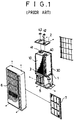
- FIG. 1 of the accompanying diagrammatic drawings illustrates a conventional air conditioner with an evaporator 10, a condenser 30 facing one face of the evaporator, an integral stationary casing 1 disposed longitudinally between the evaporator and the condenser, and cross fans 40,41 for guiding air flow toward the evaporator 10 and the condenser 30 respectively.
- respective upper and lower frames 2,3 are located at respective upper and lower ends of the casing 1.
- Under the lower frame 3 are disposed fan motors (not shown) which are connected to the cross fans, respectively.
- a compressor 5 for compressing and discharging a refrigerant.
- On the upper frame 2 are engaged supporting members 42,43 which support the upper shafts of the cross fans, respectively. Cooling air is discharged through a grill 6.
- a filter 7 removes dust from the air flow.
- Patent Abstracts of Japan vol. 007, no. 031 (M-192) (8 Feb 1993) discloses an air conditioner comprising a frame holding a condenser beneath an evaporator with two fans, each of which is driven by its own motor. This air conditioner is larger than is desirable and does not simply allow an effective method of changing from a heating to a cooling function.
- the air conditioner comprises a casing located in a place where indoor air intakes through a front portion and discharges through the same portion, and a casing located in a place where outdoor air is taken in though a rear portion and discharged through the same portion.
- Heat exchangers are stacked intersectedly and cross fans are coaxially disposed one above the other. Between the upper cross fan and the lower cross fan is placed a transmission for rotating the cross fans reversibly.
- a fan motor is placed at one end of the fans and at the opposite end of the transmission.
- This arrangement reduces the size of the air conditioner.
- the air conditioner requires an additional changeover device for reversing the flow of the refrigerant in order to heat as well as cool the air flowing through it. Furthermore, the condensate generated by the evaporator drops down onto an intermediate platform and drains out through a drain passage formed in the platform without any further use to the air conditioner, which decreases the efficiency of the air conditioner.
- Preferred embodiments of the present invention seek to provide an air conditioner which easily and effectively solves the above mentioned problems.
- An aim of preferred embodiments of the present invention is to provide an air conditioner in which both cooling and heating are achieved in one system without reversing the flow of the refrigerant in the system.
- Another aim is to provide an air conditioner in which condensate formed in an evaporator drops down to a condenser so as to increase heat loss therefrom.
- an air conditioner comprising:
- said frame comprises an intermediate platform for separating said evaporator and said condenser, an upper platform formed over the upper part of said evaporator, a lower platform formed under the lower part of said condenser, a rail formed in each platform for guiding movement of said screen, and a groove formed in each platform for restricting the movement of said evaporator and said condenser.
- said screen members comprise an upper screen member arranged movably back and forth between the front face of said evaporator and the rear face thereof and a lower screen member arranged movably back and forth between the front face of said condenser and the rear face thereof.
- said upper screen member and said lower screen member respectively comprise a screen, a pair of vertical rods for fixing respectively both vertical ends of said screen, a pair of horizontal flexible rods encompassing respectively upper and lower horizontal portions of said screen, a plurality of supporting rods disposed in said screen for reinforcing said screen, and a plurality of actuators connected to said control means for moving respectively said screen members between the front face of said evaporator and the rear face thereof and between the front face of said condenser and the rear face thereof.
- a travelling member in said control means comprises an upper travelling shaft connected to said evaporator, a lower travelling shaft connected to said condenser, and a stepping motor for operating simultaneously said upper travelling shaft and said lower travelling shaft in a reverse manner.
- a swing member in said control means comprises an upper swing shaft disposed at an end of said evaporator, a lower swing shaft disposed at an end of said condenser, and a stepping motor for operating simultaneously said upper swing shaft and said lower swing shaft in a reverse manner.
- said upper screen is disposed adjacent the rear face of said evaporator, and said lower screen is disposed adjacent the front face of said condenser when in a cooling mode, while said upper screen is disposed adjacent the front face of said evaporator, and said lower screen is disposed adjacent the rear face of said condenser when in a heating mode.
- FIGS. 2 to 6 illustrate an air conditioner in accordance with a preferred embodiment of the present invention.
- the air conditioner includes an evaporator 10 and a condenser 30 which are pivotally mounted by a control means 90 with the evaporator 10 arranged over the condenser 30. Between the evaporator 10 and the condenser 30 are disposed intermediate platform members 50 which comprise a lower intermediate platform 52 and a upper intermediate platform 51. An upper platform 70 is disposed over the evaporator 10, and a lower platform 80 is disposed beneath the condenser 30. Screen members 100, 200 comprise an upper screen member 100 for the evaporator 10 and a lower screen member 200 for the condenser 30.
- the screen members 100,200 are arranged so as to travel back and forth between the front face of the evaporator 10 and the rear face of the condenser 30 or between the front face of the condenser 30 and the rear face of the evaporator 10.
- the control member 90 for pivoting the evaporator 10 and the condenser 30 and moving the screen members 100, 200.
- a fan motor 44 for rotating cross-fans 40, 41 which forcibly move outdoor and indoor air.
- a respective rail 53 is formed for guiding travel of the screen members 100,200, respectively.
- the configuration of the rail 53 comprises a straight line adjacent a front edge of the upper and lower intermediate platforms 51,52 and a curved line extending from the forward end of the straight line as illustrated at Figure 3.
- the curved line runs toward a rear edge of the upper and lower intermediate platforms 51,52 and turns to near a starting point of the straight line as illustrated at Figure 3.
- a respective groove 54 is formed for guiding the travel of roller bearings 11 which are engaged in the upper end edge 10A and a lower end edge 10B of the evaporator and at similar positions in the condenser 30, not shown.
- a rail 53 and a groove 54 are formed, respectively, having the same configuration as above.
- an upper drain duct 55 between the rail 53 and the groove 54 for gathering condensate from the evaporator 10.
- the upper drain duct 55 has an upper drain passage 56 which is at a lower level of the drain duct 55.
- a lower drain duct 57 for collecting the condensate therefrom.
- a plurality of openings 58 are formed for dropping the condensate down to the condenser 30.
- the control member 90 includes a pivot member for moving both the evaporator 10 and the condenser 30 within a predetermined range, and a travelling member for pivoting screen members 100,200 back and forth.
- the pivot member comprises a stepping motor 91 which swings both the evaporator 10 and the condenser 30 within the range of the groove 54.
- the pivot member also comprises an upper pivot shaft 92 vertically secured to the evaporator 10.
- the pivot member also consists of a lower pivot shaft 93 vertically secured to the condenser 30.
- One end of the lower pivot shaft 93 is mounted to the lower platform 80 and the other end thereof includes a driven gear 93A which is in mechanical communication with the driving gear 92A of the upper pivot shaft 92.
- the evaporator 10 and the condenser 30 are positioned in a manner so as to pivot in opposite directions relative to each other.
- the travelling member comprises a stepping motor 95 which moves screen members 100,200 between the surfaces of the evaporator 10 and those of the condenser 30 back and forth.
- the stepping motor 95 is disposed near the stepping motor 91 of the pivot member.
- the travelling member also consists of an upper travelling shaft 96 connected to an upper screen member 100.
- One end of the upper travelling shaft 96 is pivotally mounted to the upper platform 70 and the other end thereof is connected so as to be in mechanical communication with the stepping motor 95 and extends further downwardly through the stepping motor 95 which further includes a driving gear 96A.
- the travelling member also consists of a lower travelling shaft 97 connected to a lower screen member 200.
- One end of the lower travelling shaft 97 is pivotally mounted to the lower platform 80 and the other end thereof extends upwardly with a driven gear 97A formed thereon so as to mechanically communicate with the driving gear 96A.
- the upper travelling shaft 96 and the lower travelling shaft 97 rotate in a reverse manner.
- the upper screen member is aligned adjacent to the front surface of the evaporator 10
- the lower screen member is aligned adjacent to the rear surface of the condenser 30.
- the upper screen member is aligned vice versa
- the lower screen member is aligned vice versa.
- the upper screen member 100 and the lower screen member 200 each consist of a screen 101 which has a characteristic of heat insulation.
- a pair of vertical rods 102 are fixed respectively to both vertical ends of the screen 101.
- a pair of horizontal flexible rods 103 are encompassed respectively through each upper and lower horizontal end of the screen 101 to permit the screen 101 to travel along the rail 53.
- the horizontal rod 103 is elastic to help the screen member 100 to travel in a retro or backward position.
- a plurality of supporting rods 104 are disposed in the screen 101 for reinforcing the screen 101.
- Each of the vertical rods 102 has rings 105 at the upper portion of the vertical rod 102 and the lower portion thereof, respectively.
- One end of a string 106 is tied to the ring 105 at the upper portion of the right hand vertical rod 102, and other end of a string 106 is tied to the ring 105 at a corresponding portion of the left hand vertical rod 102, as illustrated in Figure 5.
- another string is tied to the vertical rod as above.
- the string is wound up on the upper travelling shaft 96 so that when the left hand vertical rod 102 of the screen member 100 approaches toward the travelling shaft 96, the right hand vertical rod 102 is retracted away from the travelling shaft 96, and vice versa.
- the string 106 is wound up on the lower travelling shaft 97 in the reverse manner in respect to the travelling direction of the vertical rod 102.
- the lower screen 200 is placed adjacent to the front surface of the condenser 30.
- the upper screen 100 is placed adjacent to the front surface of the evaporator 10
- the lower screen 200 is placed adjacent to the rear surface of the condenser 30.
- the evaporator 10 is aligned adjacent to the indoor area as shown in Figure 7A.
- the upper screen 100 moves along the rail 53 and is disposed adjacent to the outdoors.
- the indoor air is taken into the air conditioner through the grill by the rotation of the cross fan 40.
- the flow of the air is guided by the screen 100 and is discharged back to the indoors through the cross fan 40.
- the condenser 30 is aligned adjacent to the outdoors.
- the lower screen 200 moves along the rail 53 and is disposed adjacent to the indoors.
- the outdoor air is taken into the air conditioner through the back grill by the rotation of the cross fan 41 and heat exchanges with the condenser 30.
- the flow of the air is guided by the screen 200 and is discharged back to the outdoors through the cross fan 41. Therefore, the air indoors becomes cool.
- the condensate generated from the surface of the evaporator 10 drops down to the condenser 30 through the openings 58 formed in the intermediate platforms 50.
- the condensate increase the heat loss from the condenser 30 so as to increase the efficiency of the air conditioner.
- the evaporator 10 is moved adjacent to the outdoors along the groove 54 about the upper pivot shaft 92 in a counter-clock direction.
- the upper screen 100 moves along the rail 53 in a clockwise direction by the same directional rotation of the travelling shaft 96.
- the upper screen 100 is disposed adjacent to the indoors.
- the outdoor air is taken into the air conditioner through the back grill by the rotation of the cross fan 40 and heat exchanges with the evaporator 10.
- the flow of the air is guided by the screen 100 and is discharged back to the outdoors through the cross fan 40.
- the heating and cooling are achieved in one system without reversing the flow of the refrigerant in the system. Further, the condensate of the evaporator is used to increase the efficiency of the cooling mode.
Description
- The present invention relates to air conditioners.
- Figure 1 of the accompanying diagrammatic drawings illustrates a conventional air conditioner with an
evaporator 10, acondenser 30 facing one face of the evaporator, an integralstationary casing 1 disposed longitudinally between the evaporator and the condenser, andcross fans evaporator 10 and thecondenser 30 respectively. At respective upper and lower ends of thecasing 1, respective upper andlower frames lower frame 3 are disposed fan motors (not shown) which are connected to the cross fans, respectively. Further, under thelower frame 3 is disposed acompressor 5 for compressing and discharging a refrigerant. On theupper frame 2 are engaged supportingmembers grill 6. Afilter 7 removes dust from the air flow. - However, a problem occurs because the evaporator and the condenser are juxtaposed along their faces causing the width of the air conditioner to become too massive. In the instalment of the air conditioner in a wall, a significant protruding portion of the air conditioner from the wall requires extra support means, such as brackets and the like, which detracts from the appearance of the air conditioner. Further, two fan motors are required for rotating the pair of cross fans.
- Also, Patent Abstracts of Japan vol. 007, no. 031 (M-192) (8 Feb 1993) discloses an air conditioner comprising a frame holding a condenser beneath an evaporator with two fans, each of which is driven by its own motor. This air conditioner is larger than is desirable and does not simply allow an effective method of changing from a heating to a cooling function.
- In order to resolve the problem, an air conditioner has been developed and disclosed in Japanese Utility Model Publication No. 1986 - 39233. The air conditioner comprises a casing located in a place where indoor air intakes through a front portion and discharges through the same portion, and a casing located in a place where outdoor air is taken in though a rear portion and discharged through the same portion. Heat exchangers are stacked intersectedly and cross fans are coaxially disposed one above the other. Between the upper cross fan and the lower cross fan is placed a transmission for rotating the cross fans reversibly. A fan motor is placed at one end of the fans and at the opposite end of the transmission.
- This arrangement reduces the size of the air conditioner.
- However, the air conditioner requires an additional changeover device for reversing the flow of the refrigerant in order to heat as well as cool the air flowing through it. Furthermore, the condensate generated by the evaporator drops down onto an intermediate platform and drains out through a drain passage formed in the platform without any further use to the air conditioner, which decreases the efficiency of the air conditioner.
- Preferred embodiments of the present invention seek to provide an air conditioner which easily and effectively solves the above mentioned problems.
- An aim of preferred embodiments of the present invention is to provide an air conditioner in which both cooling and heating are achieved in one system without reversing the flow of the refrigerant in the system.
- Another aim is to provide an air conditioner in which condensate formed in an evaporator drops down to a condenser so as to increase heat loss therefrom.
- According to the present invention, there is provided an air conditioner comprising:
- a frame;
- an evaporator disposed in said frame;
- a condenser disposed in said frame and arranged underneath said evaporator;
- a pair of fans disposed in said frame for forcibly moving air; and
- a fan motor operatively connected to each said fan for rotating said fan;
- the evaporator and condenser are pivotally disposed in said frame;
- a pair of screen members is arranged movably between a front face of said evaporator and a rear face thereof and between a front face of said condenser and a rear face thereof, respectively, for guiding air flow, in which screen members comprise an upper screen for the evaporator and a lower screen for the condensor; and
- control means are provided for pivoting within a predetermined range said evaporator and said condenser and for shifting said screen members simultaneously in opposite directions.
- Preferably, said frame comprises an intermediate platform for separating said evaporator and said condenser, an upper platform formed over the upper part of said evaporator, a lower platform formed under the lower part of said condenser, a rail formed in each platform for guiding movement of said screen, and a groove formed in each platform for restricting the movement of said evaporator and said condenser.
- Preferably, said screen members comprise an upper screen member arranged movably back and forth between the front face of said evaporator and the rear face thereof and a lower screen member arranged movably back and forth between the front face of said condenser and the rear face thereof.
- Preferably, said upper screen member and said lower screen member respectively comprise a screen, a pair of vertical rods for fixing respectively both vertical ends of said screen, a pair of horizontal flexible rods encompassing respectively upper and lower horizontal portions of said screen, a plurality of supporting rods disposed in said screen for reinforcing said screen, and a plurality of actuators connected to said control means for moving respectively said screen members between the front face of said evaporator and the rear face thereof and between the front face of said condenser and the rear face thereof.
- Preferably, a travelling member in said control means comprises an upper travelling shaft connected to said evaporator, a lower travelling shaft connected to said condenser, and a stepping motor for operating simultaneously said upper travelling shaft and said lower travelling shaft in a reverse manner.
- Preferably, a swing member in said control means comprises an upper swing shaft disposed at an end of said evaporator, a lower swing shaft disposed at an end of said condenser, and a stepping motor for operating simultaneously said upper swing shaft and said lower swing shaft in a reverse manner.
- Preferably, said upper screen is disposed adjacent the rear face of said evaporator, and said lower screen is disposed adjacent the front face of said condenser when in a cooling mode, while said upper screen is disposed adjacent the front face of said evaporator, and said lower screen is disposed adjacent the rear face of said condenser when in a heating mode.
- For a better understanding of the invention, and to show how the same may be carried into effect, reference will now be made, by way of example, to Figures 2 to 9 of the accompanying diagrammatic drawings, in which:
- Figure 2 is a perspective view of one example of an air conditioner embodying the present invention;
- Figure 3 is a perspective view of a frame suitable for use in the embodiment of Figure 2;
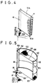
- Figure 4 is a perspective view of a swing member suitable for use in the embodiment of Figure 2;
- Figure 5 is a perspective view of a screen member connected to a travelling member, as suitable for use in the embodiment of Figure 2;
- Figure 6 is a disassembled perspective view of an intermediate platform member suitable for use in the embodiment of Figure 2;
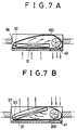
- Figure 7A is a plan view of an evaporator compartment in a cooling condition, in use of the embodiment illustrated in Figures 2 to 6;
- Figure 7B is a plan view of a condenser compartment in a cooling condition, in use of the embodiment illustrated in Figures 2 to 6;
- Figure 8A is a plan view of the evaporator compartment in a heating condition, in use of the embodiment illustrated in Figures 2 to 6;
- Figure 8B is a plan view of the condenser compartment in a heating condition, in use of the embodiment illustrated in Figures 2 to 6;
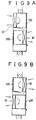
- Figure 9A is an end elevation view of the air conditioner in a cooling condition, in use of the embodiment illustrated in Figures 2 to 6; and
- Figure 9B is an end elevation view of the air conditioner in a heating condition, in use of the embodiment illustrated in Figures 2 to 6.
- Figures 2 to 6 illustrate an air conditioner in accordance with a preferred embodiment of the present invention.
- The air conditioner includes an
evaporator 10 and acondenser 30 which are pivotally mounted by a control means 90 with theevaporator 10 arranged over thecondenser 30. Between theevaporator 10 and thecondenser 30 are disposedintermediate platform members 50 which comprise a lowerintermediate platform 52 and a upper intermediate platform 51. Anupper platform 70 is disposed over theevaporator 10, and alower platform 80 is disposed beneath thecondenser 30.Screen members upper screen member 100 for theevaporator 10 and alower screen member 200 for thecondenser 30. The screen members 100,200 are arranged so as to travel back and forth between the front face of theevaporator 10 and the rear face of thecondenser 30 or between the front face of thecondenser 30 and the rear face of theevaporator 10. Between the upper intermediate platform 51 and the lowerintermediate platform 52 is disposed thecontrol member 90 for pivoting theevaporator 10 and thecondenser 30 and moving thescreen members control member 90 is disposed afan motor 44 for rotatingcross-fans - On the upper surface of the upper intermediate platform 51 and on the lower surface of the lower intermediate platform 52 a
respective rail 53 is formed for guiding travel of the screen members 100,200, respectively. The configuration of therail 53 comprises a straight line adjacent a front edge of the upper and lowerintermediate platforms 51,52 and a curved line extending from the forward end of the straight line as illustrated at Figure 3. The curved line runs toward a rear edge of the upper and lowerintermediate platforms 51,52 and turns to near a starting point of the straight line as illustrated at Figure 3. Further, in the upper surface of the upper intermediate platform 51 and in the lower surface of the lower intermediate platform 52 arespective groove 54 is formed for guiding the travel ofroller bearings 11 which are engaged in the upper end edge 10A and a lower end edge 10B of the evaporator and at similar positions in thecondenser 30, not shown. At the lower surface of theupper platform 70 and the upper surface of the lower platform 80 arail 53 and agroove 54 are formed, respectively, having the same configuration as above. - Further, as illustrated in Figure 6, at the upper surface of the upper intermediate platform 51 there is formed an
upper drain duct 55 between therail 53 and thegroove 54 for gathering condensate from theevaporator 10. Theupper drain duct 55 has anupper drain passage 56 which is at a lower level of thedrain duct 55. At the upper surface of the lowerintermediate platform 52 under theupper drain duct 55 is formed alower drain duct 57 for collecting the condensate therefrom. At the lowest level of the lower duct 57 a plurality ofopenings 58 are formed for dropping the condensate down to thecondenser 30. - At the upper surface of the
upper platform 70 and the lower surface of thelower platform 80 are engaged supportingmembers 42 43, respectively, for supporting thecross fans control member 90 includes a pivot member for moving both theevaporator 10 and thecondenser 30 within a predetermined range, and a travelling member for pivoting screen members 100,200 back and forth. The pivot member comprises a stepping motor 91 which swings both theevaporator 10 and thecondenser 30 within the range of thegroove 54. The pivot member also comprises anupper pivot shaft 92 vertically secured to theevaporator 10. One end of theupper pivot shaft 92 is mounted to theupper platform 70 and the other end thereof is connected so as to mechanically communicate with the stepping motor 91 and includes adriving gear 92A. The pivot member also consists of alower pivot shaft 93 vertically secured to thecondenser 30. One end of thelower pivot shaft 93 is mounted to thelower platform 80 and the other end thereof includes a drivengear 93A which is in mechanical communication with thedriving gear 92A of theupper pivot shaft 92. Theevaporator 10 and thecondenser 30 are positioned in a manner so as to pivot in opposite directions relative to each other. - The travelling member comprises a stepping
motor 95 which moves screen members 100,200 between the surfaces of theevaporator 10 and those of thecondenser 30 back and forth. The steppingmotor 95 is disposed near the stepping motor 91 of the pivot member. The travelling member also consists of an upper travellingshaft 96 connected to anupper screen member 100. One end of the upper travellingshaft 96 is pivotally mounted to theupper platform 70 and the other end thereof is connected so as to be in mechanical communication with the steppingmotor 95 and extends further downwardly through the steppingmotor 95 which further includes a driving gear 96A. The travelling member also consists of a lower travellingshaft 97 connected to alower screen member 200. One end of the lower travellingshaft 97 is pivotally mounted to thelower platform 80 and the other end thereof extends upwardly with a drivengear 97A formed thereon so as to mechanically communicate with the driving gear 96A. The upper travellingshaft 96 and the lower travellingshaft 97 rotate in a reverse manner. When the upper screen member is aligned adjacent to the front surface of theevaporator 10, the lower screen member is aligned adjacent to the rear surface of thecondenser 30. When the upper screen member is aligned vice versa, the lower screen member is aligned vice versa. - The
upper screen member 100 and thelower screen member 200 each consist of ascreen 101 which has a characteristic of heat insulation. A pair ofvertical rods 102 are fixed respectively to both vertical ends of thescreen 101. A pair of horizontalflexible rods 103 are encompassed respectively through each upper and lower horizontal end of thescreen 101 to permit thescreen 101 to travel along therail 53. Thehorizontal rod 103 is elastic to help thescreen member 100 to travel in a retro or backward position. A plurality of supportingrods 104 are disposed in thescreen 101 for reinforcing thescreen 101. Each of thevertical rods 102 hasrings 105 at the upper portion of thevertical rod 102 and the lower portion thereof, respectively. One end of astring 106 is tied to thering 105 at the upper portion of the right handvertical rod 102, and other end of astring 106 is tied to thering 105 at a corresponding portion of the left handvertical rod 102, as illustrated in Figure 5. At the lower portion of eachvertical rod 102, another string is tied to the vertical rod as above. The string is wound up on the upper travellingshaft 96 so that when the left handvertical rod 102 of thescreen member 100 approaches toward the travellingshaft 96, the right handvertical rod 102 is retracted away from the travellingshaft 96, and vice versa. In the lower travellingshaft 97, thestring 106 is wound up on the lower travellingshaft 97 in the reverse manner in respect to the travelling direction of thevertical rod 102. That is, when theupper screen 100 is placed adjacent to the rear surface of theevaporator 10, thelower screen 200 is placed adjacent to the front surface of thecondenser 30. When theupper screen 100 is placed adjacent to the front surface of theevaporator 10, thelower screen 200 is placed adjacent to the rear surface of thecondenser 30. - In Figures 7A,7B and 9A, a cooling operation is illustrated.
- The
evaporator 10 is aligned adjacent to the indoor area as shown in Figure 7A. Theupper screen 100 moves along therail 53 and is disposed adjacent to the outdoors. The indoor air is taken into the air conditioner through the grill by the rotation of thecross fan 40. The intaken air heat exchanges with theevaporator 10. The flow of the air is guided by thescreen 100 and is discharged back to the indoors through thecross fan 40. - In Figure 7B, the
condenser 30 is aligned adjacent to the outdoors. Thelower screen 200 moves along therail 53 and is disposed adjacent to the indoors. The outdoor air is taken into the air conditioner through the back grill by the rotation of thecross fan 41 and heat exchanges with thecondenser 30. The flow of the air is guided by thescreen 200 and is discharged back to the outdoors through thecross fan 41. Therefore, the air indoors becomes cool. Furthermore, the condensate generated from the surface of theevaporator 10 drops down to thecondenser 30 through theopenings 58 formed in theintermediate platforms 50. The condensate increase the heat loss from thecondenser 30 so as to increase the efficiency of the air conditioner. - In Figures 8A,8B and 9B, a heating operation is illustrated.
- In Figure 8A, the
evaporator 10 is moved adjacent to the outdoors along thegroove 54 about theupper pivot shaft 92 in a counter-clock direction. Theupper screen 100 moves along therail 53 in a clockwise direction by the same directional rotation of the travellingshaft 96. Theupper screen 100 is disposed adjacent to the indoors. The outdoor air is taken into the air conditioner through the back grill by the rotation of thecross fan 40 and heat exchanges with theevaporator 10. The flow of the air is guided by thescreen 100 and is discharged back to the outdoors through thecross fan 40. In Figure 8B, with a counter-clockwise rotational direction of theupper pivot shaft 92 as shown in Figure 8A, thecondenser 30 is concurrently moved adjacent to the outdoors along thegroove 54 about thelower pivot shaft 93 in a clockwise direction. With the clockwise rotation of the upper travellingshaft 96, as shown in Figure 8A, thelower screen 200 concurrently travels along therail 53 in a counter-clock wise direction by the same directional rotation of the lower travellingshaft 97. Thelower screen 200 is disposed adjacent to the outdoors. The indoor air is taken into the air conditioner through the grill by the rotation of thecross fan 41 and heat exchanged by thecondenser 30. The flow of the air is guided by thescreen 200 and is discharged back to the indoors through thecross fan 41. Therefore, the air in the indoors becomes warm. - In the above structural air conditioner, the heating and cooling are achieved in one system without reversing the flow of the refrigerant in the system. Further, the condensate of the evaporator is used to increase the efficiency of the cooling mode.
- The invention is not restricted to the details of the foregoing embodiments but by the appended claims.
Claims (7)
- An air conditioner comprising:a frame;an evaporator (10) disposed in said frame;a condenser (30) disposed in said frame and arranged underneath said evaporator;a pair of fans (40, 41) disposed in said frame for forcibly moving air; anda fan motor operatively connected to each said fan (40, 41) for rotating said fans (40, 41);characterised in that :the evaporator and condensor are pivotally disposed in said frame;a pair of screen members (100, 200) is arranged movably between a front face of said evaporator (10) and a rear face thereof and between a front face of said condenser (30) and a rear face thereof, respectively, for guiding air flow, in which screen members (100, 200) comprise an upper screen (100) for the evaporator (10) and a lower screen (200) for the condenser (30); andcontrol means are provided for pivoting within a predetermined range said evaporator (10) and said condenser (30) and for shifting said screen members (100, 200) simultaneously in opposite directions.
- An air conditioner according to claim 1, wherein said frame comprises an intermediate platform (50) for separating said evaporator (10) and said condenser (30), an upper platform (70) formed over the upper part of said evaporator (10), a lower platform (80) formed under the lower part of said condenser (30), a rail (53) formed in each platform (50, 70, 80) for guiding movement of said screen (100, 200), and a groove (54) formed in each platform (50, 70, 80) for restricting the movement of said evaporator (10) and said condenser (30).
- An air conditioner according to claim 1 or 2, wherein said screen members (100, 200) comprise an upper screen member (100) arranged movably back and forth between the front face of said evaporator (10) and the rear face thereof and a lower screen member (200) arranged movably back and forth between the front face of said condenser (30) and the rear face thereof.
- An air conditioner according to claim 3, wherein said upper screen member (100) and said lower screen member (200) respectively comprise a screen (101), a pair of vertical rods (102) for fixing respectively both vertical ends of said screen (101), a pair of horizontal flexible rods (103) encompassing respectively upper and lower horizontal portions of said screen (101), a plurality of supporting rods (104) disposed in said screen (101) for reinforcing said screen (101), and a plurality of actuators (95) connected to said control means (90) for moving respectively said screen members (100, 200) between the front face of said evaporator (10) and the rear face thereof and between the front face of said condenser (30) and the rear face thereof.
- An air conditioner according to claim 4, wherein a travelling member in said control means (90) comprises an upper travelling shaft (96) connected to said evaporator (10), a lower travelling shaft (97) connected to said condenser (30), and a stepping motor (91) for operating simultaneously said upper travelling shaft (96) and said lower travelling shaft (97) in a reverse manner.
- An air conditioner according to any of the preceding claims, wherein a swing member in said control means (90) comprises an upper swing shaft (96) disposed at an end of said evaporator (10), a lower swing shaft (97) disposed at an end of said condenser (30), and a stepping motor (95) for operating simultaneously said upper swing shaft (96) and said lower swing shaft (97) in a reverse manner.
- An air conditioner according to claim 1, wherein said upper screen (100) is disposed adjacent the rear face of said evaporator (10), and said lower screen (200) is disposed adjacent the front face of said condenser (30) when in a cooling mode, while said upper screen (100) is disposed adjacent the front face of said evaporator (10), and said lower screen (200) is disposed adjacent the rear face of said condenser (30) when in a heating mode.
Applications Claiming Priority (4)
| Application Number | Priority Date | Filing Date | Title |
|---|---|---|---|
| KR1683191 | 1991-09-27 | ||
| KR1019910016831A KR940004107B1 (en) | 1991-09-27 | 1991-09-27 | Apparatus for and method of transferring cool and hot function of air conditioner |
| KR1782691 | 1991-10-24 | ||
| KR910017826 | 1991-10-24 |
Publications (3)
| Publication Number | Publication Date |
|---|---|
| EP0534805A2 EP0534805A2 (en) | 1993-03-31 |
| EP0534805A3 EP0534805A3 (en) | 1993-10-27 |
| EP0534805B1 true EP0534805B1 (en) | 1996-08-21 |
Family
ID=26628756
Family Applications (1)
| Application Number | Title | Priority Date | Filing Date |
|---|---|---|---|
| EP92308841A Expired - Lifetime EP0534805B1 (en) | 1991-09-27 | 1992-09-28 | Air conditioner |
Country Status (5)
| Country | Link |
|---|---|
| US (1) | US5255532A (en) |
| EP (1) | EP0534805B1 (en) |
| JP (1) | JPH07104010B2 (en) |
| DE (1) | DE69212937T2 (en) |
| TW (1) | TW197492B (en) |
Cited By (3)
| Publication number | Priority date | Publication date | Assignee | Title |
|---|---|---|---|---|
| WO2004088209A1 (en) * | 2003-04-03 | 2004-10-14 | Air-Aroz Pty Ltd | Means and method of providing localised cooling |
| CN1755274B (en) * | 2004-09-29 | 2010-05-05 | 乐金电子(天津)电器有限公司 | Louver type grille window of integral air conditioner |
| CN1755224B (en) * | 2004-09-29 | 2010-05-05 | 乐金电子(天津)电器有限公司 | Louver type grid window of integral air conditioner |
Families Citing this family (13)
| Publication number | Priority date | Publication date | Assignee | Title |
|---|---|---|---|---|
| US5533357A (en) * | 1995-02-15 | 1996-07-09 | Carrier Corporation | Air conditioning apparatus |
| DE10353046A1 (en) * | 2003-11-13 | 2005-06-09 | Lessing, Jürgen | Cooling device, in particular for cooling cold rooms |
| ES2226593B1 (en) * | 2004-11-19 | 2006-04-16 | Bsh Electrodomesticos España, S.A. | MOBILE CONDITIONING AIR EQUIPMENT. |
| US7752863B2 (en) * | 2006-07-03 | 2010-07-13 | Lg Electronics Inc. | Air conditioner |
| ITBO20110687A1 (en) * | 2011-12-02 | 2013-06-03 | Giuliano Ungarelli | CONDENSATION AND HEAT WATER RECOVERY CONDITIONER |
| US9157670B2 (en) | 2013-10-25 | 2015-10-13 | Kooltronic, Inc. | Hazardous location heat transfer unit |
| US20180283704A1 (en) * | 2015-12-18 | 2018-10-04 | Mitsubishi Electric Corporation | Outdoor unit of refrigeration cycle apparatus |
| US11085653B2 (en) | 2016-10-16 | 2021-08-10 | Premium Home Comfort, Inc. | Air conditioner and an air conditioner housing |
| CN108917025A (en) * | 2018-08-20 | 2018-11-30 | 珠海格力电器股份有限公司 | Mobile air conditioner |
| US11187418B1 (en) * | 2019-01-04 | 2021-11-30 | Katerra Inc. | HVAC system with modular architecture |
| KR102565503B1 (en) | 2019-01-29 | 2023-08-11 | 삼성전자주식회사 | Air conditioner |
| CN210921603U (en) * | 2019-11-29 | 2020-07-03 | 广东美的制冷设备有限公司 | Integral air conditioner |
| CN111059708A (en) * | 2019-12-06 | 2020-04-24 | 珠海格力电器股份有限公司 | Air conditioner with rotary display |
Family Cites Families (6)
| Publication number | Priority date | Publication date | Assignee | Title |
|---|---|---|---|---|
| US3084522A (en) * | 1960-06-01 | 1963-04-09 | Whirlpool Co | Reverse air cycle air conditioner |
| DE1454612C3 (en) * | 1964-12-09 | 1974-11-07 | Nikolaus 7141 Aldingen Laing | Heat pump with two heat exchangers and cross-flow fans assigned to them |
| US4297855A (en) * | 1980-05-21 | 1981-11-03 | General Electric Company | Air valve heat pump |
| US4359876A (en) * | 1981-02-17 | 1982-11-23 | General Electric Company | Room air conditioner sensor application |
| JPS57184843A (en) * | 1981-05-08 | 1982-11-13 | Susumu Kuniya | Air-conditioner with switching dumper |
| JPS6139233A (en) * | 1984-07-27 | 1986-02-25 | Matsushita Electric Ind Co Ltd | Manufacture of metal thin film magnetic recording medium |
-
1992
- 1992-09-26 TW TW081107646A patent/TW197492B/zh active
- 1992-09-28 DE DE69212937T patent/DE69212937T2/en not_active Expired - Fee Related
- 1992-09-28 EP EP92308841A patent/EP0534805B1/en not_active Expired - Lifetime
- 1992-09-28 JP JP4258060A patent/JPH07104010B2/en not_active Expired - Lifetime
- 1992-09-28 US US07/951,754 patent/US5255532A/en not_active Expired - Fee Related
Cited By (3)
| Publication number | Priority date | Publication date | Assignee | Title |
|---|---|---|---|---|
| WO2004088209A1 (en) * | 2003-04-03 | 2004-10-14 | Air-Aroz Pty Ltd | Means and method of providing localised cooling |
| CN1755274B (en) * | 2004-09-29 | 2010-05-05 | 乐金电子(天津)电器有限公司 | Louver type grille window of integral air conditioner |
| CN1755224B (en) * | 2004-09-29 | 2010-05-05 | 乐金电子(天津)电器有限公司 | Louver type grid window of integral air conditioner |
Also Published As
| Publication number | Publication date |
|---|---|
| TW197492B (en) | 1993-01-01 |
| DE69212937T2 (en) | 1997-02-27 |
| JPH07104010B2 (en) | 1995-11-08 |
| EP0534805A2 (en) | 1993-03-31 |
| EP0534805A3 (en) | 1993-10-27 |
| JPH05203189A (en) | 1993-08-10 |
| US5255532A (en) | 1993-10-26 |
| DE69212937D1 (en) | 1996-09-26 |
Similar Documents
| Publication | Publication Date | Title |
|---|---|---|
| EP0534805B1 (en) | Air conditioner | |
| CA2409963C (en) | Hybrid window/split air treatment appliance | |
| KR101781845B1 (en) | Indoor unit of air conditioner | |
| CN100451475C (en) | Air conditioner | |
| JP2004012060A (en) | Indoor unit for air conditioner and air conditioner | |
| US5094089A (en) | Driving system for dual tangential blowers in an air conditioner | |
| JP2902606B2 (en) | Air conditioner intake grill opening and closing device | |
| JP3293976B2 (en) | Air conditioner wind direction changing device | |
| JPH08178338A (en) | Indoor device of air conditioner | |
| CA2031425A1 (en) | Air conditioner with dual cross flow blowers | |
| CN100362288C (en) | Air outlet structure of air conditioner | |
| JP4752142B2 (en) | Indoor unit for air conditioner | |
| KR200202068Y1 (en) | Air conditioner | |
| KR20090008629A (en) | Air conditioner | |
| JP3947804B2 (en) | Air conditioner | |
| JPH0742046Y2 (en) | Air conditioner | |
| KR940004107B1 (en) | Apparatus for and method of transferring cool and hot function of air conditioner | |
| CN212987426U (en) | Air outlet-adjustable air conditioner indoor unit and air conditioning system | |
| KR100236342B1 (en) | Convertible type air conditioner | |
| CN215597691U (en) | Air duct assembly, water purification module and air conditioner | |
| CN212690271U (en) | Horizontal strong heat dissipation automobile air conditioner compressor | |
| CN218379865U (en) | Air conditioner air-out baffle | |
| CN216143816U (en) | Air conditioner indoor unit and air conditioning system | |
| KR100274987B1 (en) | Indoor unit of multi-split air conditioner | |
| JPH0718896Y2 (en) | Air conditioner |
Legal Events
| Date | Code | Title | Description |
|---|---|---|---|
| PUAI | Public reference made under article 153(3) epc to a published international application that has entered the european phase |
Free format text: ORIGINAL CODE: 0009012 |
|
| AK | Designated contracting states |
Kind code of ref document: A2 Designated state(s): DE FR GB |
|
| PUAL | Search report despatched |
Free format text: ORIGINAL CODE: 0009013 |
|
| AK | Designated contracting states |
Kind code of ref document: A3 Designated state(s): DE FR GB |
|
| 17P | Request for examination filed |
Effective date: 19940416 |
|
| 17Q | First examination report despatched |
Effective date: 19950307 |
|
| GRAH | Despatch of communication of intention to grant a patent |
Free format text: ORIGINAL CODE: EPIDOS IGRA |
|
| GRAH | Despatch of communication of intention to grant a patent |
Free format text: ORIGINAL CODE: EPIDOS IGRA |
|
| GRAA | (expected) grant |
Free format text: ORIGINAL CODE: 0009210 |
|
| AK | Designated contracting states |
Kind code of ref document: B1 Designated state(s): DE FR GB |
|
| REF | Corresponds to: |
Ref document number: 69212937 Country of ref document: DE Date of ref document: 19960926 |
|
| ET | Fr: translation filed | ||
| PLBE | No opposition filed within time limit |
Free format text: ORIGINAL CODE: 0009261 |
|
| STAA | Information on the status of an ep patent application or granted ep patent |
Free format text: STATUS: NO OPPOSITION FILED WITHIN TIME LIMIT |
|
| 26N | No opposition filed | ||
| PGFP | Annual fee paid to national office [announced via postgrant information from national office to epo] |
Ref country code: FR Payment date: 19990909 Year of fee payment: 8 |
|
| PGFP | Annual fee paid to national office [announced via postgrant information from national office to epo] |
Ref country code: GB Payment date: 19990922 Year of fee payment: 8 |
|
| PGFP | Annual fee paid to national office [announced via postgrant information from national office to epo] |
Ref country code: DE Payment date: 19991001 Year of fee payment: 8 |
|
| PG25 | Lapsed in a contracting state [announced via postgrant information from national office to epo] |
Ref country code: GB Free format text: LAPSE BECAUSE OF NON-PAYMENT OF DUE FEES Effective date: 20000928 |
|
| GBPC | Gb: european patent ceased through non-payment of renewal fee |
Effective date: 20000928 |
|
| PG25 | Lapsed in a contracting state [announced via postgrant information from national office to epo] |
Ref country code: FR Free format text: LAPSE BECAUSE OF NON-PAYMENT OF DUE FEES Effective date: 20010531 |
|
| PG25 | Lapsed in a contracting state [announced via postgrant information from national office to epo] |
Ref country code: DE Free format text: LAPSE BECAUSE OF NON-PAYMENT OF DUE FEES Effective date: 20010601 |
|
| REG | Reference to a national code |
Ref country code: FR Ref legal event code: ST |