EP0534475A1 - Cable loop insert - Google Patents
Cable loop insert Download PDFInfo
- Publication number
- EP0534475A1 EP0534475A1 EP92116487A EP92116487A EP0534475A1 EP 0534475 A1 EP0534475 A1 EP 0534475A1 EP 92116487 A EP92116487 A EP 92116487A EP 92116487 A EP92116487 A EP 92116487A EP 0534475 A1 EP0534475 A1 EP 0534475A1
- Authority
- EP
- European Patent Office
- Prior art keywords
- insert
- rope loop
- loop
- formwork
- concrete
- Prior art date
- Legal status (The legal status is an assumption and is not a legal conclusion. Google has not performed a legal analysis and makes no representation as to the accuracy of the status listed.)
- Granted
Links
- 239000004567 concrete Substances 0.000 claims abstract description 27
- 238000004519 manufacturing process Methods 0.000 claims abstract description 11
- 238000009415 formwork Methods 0.000 claims description 20
- 239000011178 precast concrete Substances 0.000 claims description 11
- 239000002131 composite material Substances 0.000 claims description 8
- 239000004033 plastic Substances 0.000 claims description 4
- 229920003023 plastic Polymers 0.000 claims description 4
- 238000004873 anchoring Methods 0.000 claims description 2
- 230000002787 reinforcement Effects 0.000 claims description 2
- 230000000295 complement effect Effects 0.000 claims 1
- 238000009434 installation Methods 0.000 claims 1
- 230000003014 reinforcing effect Effects 0.000 abstract description 6
- 238000007789 sealing Methods 0.000 abstract description 5
- 150000001875 compounds Chemical group 0.000 abstract description 4
- 238000009416 shuttering Methods 0.000 abstract 1
- 230000006870 function Effects 0.000 description 8
- 239000000463 material Substances 0.000 description 4
- 230000001681 protective effect Effects 0.000 description 3
- 229910000831 Steel Inorganic materials 0.000 description 2
- 238000005452 bending Methods 0.000 description 2
- 238000005266 casting Methods 0.000 description 2
- 239000010959 steel Substances 0.000 description 2
- 229920002430 Fibre-reinforced plastic Polymers 0.000 description 1
- 239000002775 capsule Substances 0.000 description 1
- 230000006835 compression Effects 0.000 description 1
- 238000007906 compression Methods 0.000 description 1
- 238000010276 construction Methods 0.000 description 1
- 239000011151 fibre-reinforced plastic Substances 0.000 description 1
- 238000001746 injection moulding Methods 0.000 description 1
- 238000010137 moulding (plastic) Methods 0.000 description 1
- 230000000149 penetrating effect Effects 0.000 description 1
- 230000035515 penetration Effects 0.000 description 1
- 230000009993 protective function Effects 0.000 description 1
- 238000000926 separation method Methods 0.000 description 1
- 239000000243 solution Substances 0.000 description 1
Images


Classifications
-
- E—FIXED CONSTRUCTIONS
- E04—BUILDING
- E04B—GENERAL BUILDING CONSTRUCTIONS; WALLS, e.g. PARTITIONS; ROOFS; FLOORS; CEILINGS; INSULATION OR OTHER PROTECTION OF BUILDINGS
- E04B1/00—Constructions in general; Structures which are not restricted either to walls, e.g. partitions, or floors or ceilings or roofs
- E04B1/38—Connections for building structures in general
- E04B1/41—Connecting devices specially adapted for embedding in concrete or masonry
- E04B1/4114—Elements with sockets
- E04B1/415—Elements with sockets with captive and extendable anchoring parts, e.g. spring-loaded bolts, hanging rings
-
- B—PERFORMING OPERATIONS; TRANSPORTING
- B28—WORKING CEMENT, CLAY, OR STONE
- B28B—SHAPING CLAY OR OTHER CERAMIC COMPOSITIONS; SHAPING SLAG; SHAPING MIXTURES CONTAINING CEMENTITIOUS MATERIAL, e.g. PLASTER
- B28B23/00—Arrangements specially adapted for the production of shaped articles with elements wholly or partly embedded in the moulding material; Production of reinforced objects
- B28B23/005—Arrangements specially adapted for the production of shaped articles with elements wholly or partly embedded in the moulding material; Production of reinforced objects with anchoring or fastening elements for the shaped articles
-
- E—FIXED CONSTRUCTIONS
- E04—BUILDING
- E04G—SCAFFOLDING; FORMS; SHUTTERING; BUILDING IMPLEMENTS OR AIDS, OR THEIR USE; HANDLING BUILDING MATERIALS ON THE SITE; REPAIRING, BREAKING-UP OR OTHER WORK ON EXISTING BUILDINGS
- E04G21/00—Preparing, conveying, or working-up building materials or building elements in situ; Other devices or measures for constructional work
- E04G21/12—Mounting of reinforcing inserts; Prestressing
- E04G21/125—Reinforcement continuity box
- E04G21/126—Reinforcement continuity box for cable loops
-
- E—FIXED CONSTRUCTIONS
- E04—BUILDING
- E04G—SCAFFOLDING; FORMS; SHUTTERING; BUILDING IMPLEMENTS OR AIDS, OR THEIR USE; HANDLING BUILDING MATERIALS ON THE SITE; REPAIRING, BREAKING-UP OR OTHER WORK ON EXISTING BUILDINGS
- E04G21/00—Preparing, conveying, or working-up building materials or building elements in situ; Other devices or measures for constructional work
- E04G21/14—Conveying or assembling building elements
- E04G21/142—Means in or on the elements for connecting same to handling apparatus
Definitions
- the present invention relates to a cable loop insert for the connection of prefabricated concrete parts, in particular for the end face connection of concrete wall elements to one another, consisting of a closed or an open-ended, spring-elastic cable loop and an insert serving as a mold core, which elastically rests on the formwork during the manufacture of the precast concrete part encloses the angled closed head portion of the rope loop.
- Holding devices are known as a generic holding device or reinforcing composite elements for the connection of cast slabs or block-shaped molded mass parts to one another, in which eyelet-shaped holding elements protrude from a recess in the composite surface of the prefabricated concrete parts or molded mass parts determined by an insert shell part.
- the eyelet-shaped holding element can be an erectable steel bracket or an elastic wire loop, which is accommodated in an insert shell part in the form of an unstructured plastic housing.
- the holding element in the form of an erectable steel bracket or an elastic wire loop is fixed in its position by a nose-shaped attachment in the insert shell part.
- This insert known from the prior art essentially has two functions.
- this molded part should enclose the holding element in a sealing manner, so that the concrete mass flowing in during the production of the molded mass parts does not come into contact with the holding element.
- it should be designed in such a way that the holding element can be erected in its position of use or composite position without any problems and without great technical effort.
- this molded part had to be made of high-quality plastic, in particular of fiber-reinforced plastic material.
- the second and probably just as important function is the fixation of the holding element within the insert shell part, because the holding element should be fixed within the sealing and protective enclosing molded part in an angled shape or in a shape that has a bending moment, which is an embodiment or an order of magnitude made of the insert part necessary, which extended from the narrowest radius of curvature of the holding element in both directions of the holding element to such an extent that the element was fixed in the desired radius of curvature.
- the insert shell part had to be designed to be disproportionately large and stable, which, as already mentioned, appeared to be too costly for the actual intended use within molded concrete parts.
- the essential essence of the invention lies in the fact that a retaining bracket is additionally arranged in the insert shell part, which deforms and pre-stresses the cable loop in a flexurally elastic manner and fixes it at least essentially at right angles without stressing the insert shell part with these mechanical stresses.
- the solution according to the invention consistently separates the protective function or the enveloping function from the holding and fixing function.
- the actual insert shell part can seal the head section of the rope loop both on the concrete side and on the formwork side and prevent the casting compound from penetrating into the head section of the rope loop without it having to be made of expensive high-quality and high-strength material.
- the support bracket additionally arranged according to the invention in the insert shell part receives the entire rope loop in an elastically deforming manner and fixes the rope loop completely without the involvement of the insert shell part.
- the head sections of the rope loops to be erected in the bonded position must have a prescribed length for the secure bond, which cannot be the case if the head sections of the rope loops are fixed at right angles by the aforementioned .
- This right-angled fixation on the formwork side is necessary in order to anchor the entire cable loop insert firmly in the concrete by pouring in during the manufacture of the precast concrete elements or wall elements.
- the head section of the rope loop is angled and fixed to the formwork during the manufacture of the finished parts.
- the rope loop can be closed or open-ended on the concrete side and can even be equipped with additional angled end parts and reinforcing elements at its ends for better anchoring in the molded part.
- the head section which straightens up spontaneously by elastic resetting after being released from an abutment in the holding bracket is designed as a loop.
- a cross bolt between the side surfaces of the short U-profile section fixes and clamps the inserted rope loop between the abutment for the rope loop head section and the bottom surface of the U-profile.
- this clamping of the cable loop into the support bracket is carried out in such a way that the entire cable loop is inserted into the support bracket from its flat configuration while being bent, an angled section of the head portion of the cable loop being angled onto the abutment. If the cable loop is inserted and angled in the holding bracket in this way, the cable loop is fixed or clamped by the cross bolt, which is inserted for this purpose or shot into the U-profile.
- the rope loop preassembled in this way is now fixed in a right-angled, angled shape and is then inserted into an insert shell part.
- the angled head section of the rope loop is covered by the insert shell part and lies against the formwork side, the longer part of the rope loop body is fixed in such a way that it protrudes into the prefabricated concrete part.
- the insert shell part takes up both the head section of the rope loop and the support bracket and encloses both both formwork and concrete sealing.
- the insert shell part is configured so that it forms a mold core on the concrete side to form a locking cavity in the precast concrete part.
- the insert shell part is configured differently in its longitudinal dimension and also in its concrete-side dimension, depending on the size and shape of the cavity to be formed, as the mold core for forming this cavity in the precast concrete part. If the insert shell part only has to fulfill an enveloping function, it is preferably designed as a cheap and easy-to-produce blister pack.
- the formwork-side part of the insert shell part or the blister pack has, for example, a smooth edge and outer edge area onto which a protective plate provided with a guide can be pushed.
- the flat formwork-side cover of the insert shell part is detachably clipped onto this shell part.
- the insert shell part can be equipped with mounting brackets or mounting openings for fastening to the formwork.
- These mounting brackets or openings are advantageously arranged on the smooth outer edge regions or opposite one another on the smooth edge regions or on or in molded-on tabs.
- the insert shell part according to the invention which has an additional retaining bracket, has the advantage that, on the one hand, the retaining bracket, as a relatively small, compact construction, fixes the rope loop at a right angle, whereby this preassembled rope loop retaining part is received by the insert shell part and only has to be sealed by it.
- the material used for the insert shell part can be an inexpensive blister-like profile-stiffened plastic capsule.
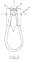
- the cable loop insert part essentially consists of a cable loop 2 with a head section 3, a support bracket 4 with a bolt 5 and an all-encompassing insert part 1, which in turn is formed in two parts and consists of an insert shell part 11 and a flat cover 12 on the formwork side.
- the insert shell part 11 and the cover 12 are additionally supported against one another by profile elements 13.
- the bracket 4 is designed as a robust and compact U-profile section, a manufactured by the injection molding process Plastic molding.
- the bracket 4 takes the rope loop 2 elastically deforming and at least substantially at right angles.
- the two free ends of the wire rope protruding into the concrete part are positively connected to each other to form a loop.
- the head section 3 of the rope loop 2 is in any case designed as a closed loop.
- the support bracket 4 is a short U-section and consists of a bottom surface 7 and an abutment 8 which at least partially closes the U-section.
- the U-section is open on the concrete side with an abutment 8 on the formwork side for the head section 3 of the cable loop 2.
- a cross bolt 5 clamps the inserted cable loop 2 between the formwork-side abutment 8 and the bottom surface 7 of the U-profile.
- the cross bolt 5 is expediently mounted after the cable loop 2 has been inserted into the holding bracket 4.
- the abutment 8 of the head part 3 of the cable loop is slotted in the middle or has a central through-channel or a central recess in which the head part 3 of the cable loop can be erected from the bent or angled position into its position intended for the manufacture of the precast element composite .
- This central recess extends essentially through the entire abutment.
- the bottom surface 7 of the U-profile which extends at least substantially at right angles to the abutment 8, has reinforcing ribs 9 which increase in the direction of the formwork side. These reinforcing ribs 9 are configured as a function of the diameter and consequently as a function of the size of the bending forces to be absorbed.
- the reinforcing ribs 9 are formed in an extension of the central recess in the abutment, on the outside of the bottom surface 7 of the U-profile.
- the inside of the bottom surface 7 of the U-profile is equipped with guide grooves 6 which receive the closed part of the rope loop which projects into the concrete.
- These guide grooves 6 essentially have the task of the rope loop at a predetermined angle and in a central position in the bracket to fix and thus prevent the rope loop from twisting or slipping out of the specified position. They also serve to seal the interior of the insert against penetration of casting compound when pouring the precast concrete parts.
- the rope loop which is clamped and fixed in this way, is inserted into the insert shell part to produce the precast concrete elements or concrete wall elements.
- the insert shell part 11 is dimensioned such that it surrounds the head section 3 of the rope loop 2 and the holding bracket 4 in a sealing manner on the concrete side.
- the insert shell part has a profiled edge onto which a protective plate provided with a guide can be pushed or clipped on.
- the manufacture of the precast concrete elements or wall elements is carried out in such a way that several pre-assembled cable loop insert parts are attached to the formwork at a distance from one another, if necessary even only placed on or placed on the formwork, the prepared formwork body is then poured out with concrete and thereby the rope loops are cast in and thus firmly anchored. After the concrete parts have hardened, the formwork is removed. The head sections of the rope loops, which are encased in the insert shell part or in the blister pack, remain on the composite sides.
- the cover is first removed from the insert shell part 11 and then the head section 3 of the rope loop 2 is released from the abutment 8 of the support bracket 4 by a short compression and guided into its intended functional position through the centrally open recess in the abutment 8 .
- a short compression and guided into its intended functional position through the centrally open recess in the abutment 8 .
- Often guiding through this open recess in the abutment is not necessary at all, since the release of the locking mechanism automatically causes the spring-elastic reinforcement elements or the rope loops to jump out of the tensioned into the relaxed free position.
Landscapes
- Engineering & Computer Science (AREA)
- Architecture (AREA)
- Structural Engineering (AREA)
- Mechanical Engineering (AREA)
- Civil Engineering (AREA)
- Electromagnetism (AREA)
- Physics & Mathematics (AREA)
- Manufacturing & Machinery (AREA)
- Chemical & Material Sciences (AREA)
- Ceramic Engineering (AREA)
- Manufacturing Of Tubular Articles Or Embedded Moulded Articles (AREA)
- Joining Of Building Structures In Genera (AREA)
- Moulds, Cores, Or Mandrels (AREA)
Abstract
Description
Die vorliegende Erfindung betrifft ein Seilschlaufeneinlegeteil für den Verbund von Betonfer-tigteilen, insbesondere für den Stirnseitenverbund von Betonwandelementen untereinander, bestehend aus einer geschlossenen oder einer offenendig verklemmten federelastischen Seilschlaufe und einem als Formkern dienenden Einlegeteil, das den bei der Herstellung des Betonfertigteils elastisch auf die Schalung abgewinkelten geschlossenen Kopfabschnitt der Seilschlaufe umschließt.The present invention relates to a cable loop insert for the connection of prefabricated concrete parts, in particular for the end face connection of concrete wall elements to one another, consisting of a closed or an open-ended, spring-elastic cable loop and an insert serving as a mold core, which elastically rests on the formwork during the manufacture of the precast concrete part encloses the angled closed head portion of the rope loop.
Als gattungsgemäße Haltevorrichtung oder Bewehrungsverbundelemente für den Verbund von gegossenen Platten oder blockförmigen Masseformteilen untereinander sind Haltevorrichtungen bekannt, bei denen ösenförmige Halteelemente aus einer durch ein Einlegeschalenteil bestimmten Ausnehmung in der Verbundfläche der Betonfertigteile bzw. Masseformteile hervorragen. Das ösenförmige Halteelement kann dabei ein aufrichtbarer Stahlbügel oder eine elastische Drahtschlaufe sein, die in einem Einlegeschalenteil in Form eines unstrukturierten Plastikgehäuses untergebracht ist. Das Halteelement in Form eines aufrichtbaren Stahlbügels oder einer elastischen Drahtschlaufe wird dabei durch einen nasenförmigen Ansatz im Einlegeschalenteil in seiner Position fixiert. Dieses nach dem Stand der Technik bekannte Einlegeteil hat im wesentlichen zwei Funktionen zu erfüllen. Zum einen soll es das Halteelement dichtend umschließen, so daß die bei der Herstellung der Masseformteile zufließenden Betonmasse nicht mit dem Halteelement in Berührung kommt. Zum anderen soll es so ausgestaltet sein, daß das Halteelement problemlos und ohne großen technischen Aufwand in seiner Gebrauchslage oder Verbundlage aufrichtbar ist. Um das Halteelement, bzw. die unterliegende Halteschlaufe gegen den Druck des Betonflusses der bei der Herstellung der Formteile auf derartige Einlegeschalenteile einwirkt standzuhalten mußte dieses Formteil aus hochwertigem Kunststoff, insbesondere aus faserverstärktem Kunststoffmaterial hergestellt werden.Holding devices are known as a generic holding device or reinforcing composite elements for the connection of cast slabs or block-shaped molded mass parts to one another, in which eyelet-shaped holding elements protrude from a recess in the composite surface of the prefabricated concrete parts or molded mass parts determined by an insert shell part. The eyelet-shaped holding element can be an erectable steel bracket or an elastic wire loop, which is accommodated in an insert shell part in the form of an unstructured plastic housing. The holding element in the form of an erectable steel bracket or an elastic wire loop is fixed in its position by a nose-shaped attachment in the insert shell part. This insert known from the prior art essentially has two functions. On the one hand, it should enclose the holding element in a sealing manner, so that the concrete mass flowing in during the production of the molded mass parts does not come into contact with the holding element. On the other hand, it should be designed in such a way that the holding element can be erected in its position of use or composite position without any problems and without great technical effort. Around the holding element or the underlying holding loop against the pressure of the concrete flow during the manufacture of the molded parts To act on such insert shell parts, this molded part had to be made of high-quality plastic, in particular of fiber-reinforced plastic material.
Nachteilig an diesen beschriebenen Einlegeteilen ist, daß der Verwendung von relativ hochwertigen Materialien diese Einlegeschalenteile wesentlich verteuert, was unter anderem einen Grund dafür darstellte, daß sie keine praktische Anwendung fanden. So praktisch und arbeitserleichternd sie auch konzipiert waren, da sie ein Aufrichten der Halteelemente in die Verbundlage doch wesentlich erleichtern so wenig wurden sie benutzt, weil sie für den Verwendungszweck ihren eigentlichen Verwendungszweck um ein vielfaches zu hohe Herstellungskosten aufwiesen. Als zweite und wahrscheinlich ebenso wichtige Funktion ist die Fixierung des Halteelementes innerhalb des Einlegeschalenteiles zu nennen, denn das Halteelement sollte innerhalb des dichtend und schützend umschließenden Formteiles in einer abgewinkelten, bzw. einer ein Biegemoment aufweisenden Form fixiert werden, was einer Ausgestaltung bzw. eine Größenordnung des Einlageteiles notwendig machte, die sich vom engsten Krümmungsradius des Halteelementes in beide Richtungen des Haltelementes soweit erstreckte, daß das Element im gewünschten Krümmungsradius fixiert war. Um dies zu erreichen, mußte das Einlegeschalenteil unverhältnismäßig groß und stabil ausgestaltet sein, was wie schon gesagt für den eigentlichen Verwendungszweck innerhalb von Betonformteilen als zu kostenaufwendig erschien.A disadvantage of these described inserts is that the use of relatively high quality materials makes these inserts considerably more expensive, which among other things was a reason why they were not used in practice. As practical as they were designed to make work easier, they made it much easier to erect the holding elements in the composite layer, so little were they used because they had their actual intended use many times too high for the intended use. The second and probably just as important function is the fixation of the holding element within the insert shell part, because the holding element should be fixed within the sealing and protective enclosing molded part in an angled shape or in a shape that has a bending moment, which is an embodiment or an order of magnitude made of the insert part necessary, which extended from the narrowest radius of curvature of the holding element in both directions of the holding element to such an extent that the element was fixed in the desired radius of curvature. In order to achieve this, the insert shell part had to be designed to be disproportionately large and stable, which, as already mentioned, appeared to be too costly for the actual intended use within molded concrete parts.
Ausgehend von diesem Stand der Technik ist es die Aufgabe der vorliegenden Erfindung die ansich bekannten Seilschlaufeneinlegeteile bei zumindestens gleichen Funktionseigenschaften durch konstruktive Maßnahmen das gesamte Seilschlaufeneinlegeteil in seiner Herstellung wesentlich kostengünstiger zu gestalten und damit für den praktischen Einsatz attraktiv zu machen.Based on this prior art, it is the object of the present invention to design the known rope loop inserts with at least the same functional properties by constructive measures to make the entire rope loop insert considerably less expensive to manufacture and thus to make it attractive for practical use.
Diese Aufgabe wird durch ein Seilschlaufeneinlegeteil für den Verbund von Betonfertigteilen gemäß der Lehre des Patentanspruchs 1 gelöst.This object is achieved by a rope loop insert for the connection of precast concrete parts according to the teaching of claim 1.
Mit anderen Worten, der wesentliche Kern der Erfindung liegt darin, dass im Einlegeschalenteil zusätzlich ein Haltebock angeordnet ist, der die Seilschlaufe biegeelastisch ver-formt und vorspannt und zumindest im wesentlichen rechtwinklig einspannend fixiert, ohne das Einlegeschalenteil mit diesen mechanischen Spannungen zu belasten. Die erfindungs-gemäße Lösung trennt konsequent die Schutzfunktion bzw. die Einhüllfunktion von der Halte- und Fixierfunktion. Durch diese Trennung beider Funktionen voneinander kann das eigentliche Einlegeschalenteil sowohl betonseitig als auch schalungsseitig den Kopfabschnitt der Seilschlaufe dichtend umschließen und ein Eindringen der Betonvergußmasse in den Kopfabschnitt der Seilschlaufe verhindern, ohne dass es aus teurem hochwertigen und hochfestem Werkstoff zu bestehen braucht.In other words, the essential essence of the invention lies in the fact that a retaining bracket is additionally arranged in the insert shell part, which deforms and pre-stresses the cable loop in a flexurally elastic manner and fixes it at least essentially at right angles without stressing the insert shell part with these mechanical stresses. The solution according to the invention consistently separates the protective function or the enveloping function from the holding and fixing function. As a result of this separation of the two functions from one another, the actual insert shell part can seal the head section of the rope loop both on the concrete side and on the formwork side and prevent the casting compound from penetrating into the head section of the rope loop without it having to be made of expensive high-quality and high-strength material.
Der erfindungsgemäß zusätzlich im Einlegeschalenteil angeordnete Haltebock nimmt die gesamte Seilschlaufe elastisch verformend auf und fixiert die Seilschlaufe völlig ohne Beteiligung des Einlegeschalenteils.The support bracket additionally arranged according to the invention in the insert shell part receives the entire rope loop in an elastically deforming manner and fixes the rope loop completely without the involvement of the insert shell part.
Neben den Problemen bei der Montage treten auch sicherheitstechnische Probleme auf, denn die in Verbundstellung aufzurichtenden Kopfabschnitte der Seilschlaufen haben für den sicheren Verbund eine vorgeschriebene Länge aufzuweisen, die schon in dem Fall nicht gegeben sein kann wenn die Kopfabschnitte der Seilschlaufen durch die vorgenanntenchen rechtwinklig einspannend fixiert. Diese rechtwinklig einspannende Fixierung an der Schalungsseite ist notwendig, um das gesamte Seilschlaufeneinlegeteil bei der Herstellung der Betonfertigteile bzw. der Wandelemente fest im Beton durch Eingießen zu verankern. Der Kopfabschnitt der Seilschlaufe ist während der Herstellung der Fertigteile abgewinkelt an der Schalung fixiert. Die Seilschlaufe kann dabei betonseitig geschlossen oder offenendig ausgebildet sein und an ihren Enenden zur besseren Verankerung im Formteil sogar mit zusätzlichen abgewinkelten Endteilen und Armierungselementen ausgerüstet sein.In addition to the problems during assembly, there are also safety-related problems, because the head sections of the rope loops to be erected in the bonded position must have a prescribed length for the secure bond, which cannot be the case if the head sections of the rope loops are fixed at right angles by the aforementioned . This right-angled fixation on the formwork side is necessary in order to anchor the entire cable loop insert firmly in the concrete by pouring in during the manufacture of the precast concrete elements or wall elements. The head section of the rope loop is angled and fixed to the formwork during the manufacture of the finished parts. The rope loop can be closed or open-ended on the concrete side and can even be equipped with additional angled end parts and reinforcing elements at its ends for better anchoring in the molded part.
Der in die Verbundstellung sich nach Lösen aus einem Widerlager im Haltebock spontan durch elastisches Rückstellen aufrichtende Kopfabschnitt ist als Schleife ausgebildet.The head section which straightens up spontaneously by elastic resetting after being released from an abutment in the holding bracket is designed as a loop.
Ein Querbolzen zwischen den Seitenflächen des kurzen U-Profilabschnittes fixiert und spannt die eingelegte Seilschlaufe zwischen dem Widerlager für den Seilschlaufenkopfabschnitt und der Bodenfläche des U-Profiles winklig ein. Bei der Vormontage des Seilschlaufeneinlegeteils erfolgt diese Einspannung der Seilschlaufe in den Haltebock derart, daß die gesamte Seilschlaufe aus ihrer ebenen Konfiguration unter Biegen in den Haltebock eingelegt wird, wobei ein fussseitiger Abschnitt des Kopfabschnitts der Seilschlaufe auf das Widerlager abgewinkelt wird. Ist die Seilschlaufe derartig in den Haltebock eingelegt und abgewinkelt, so erfolgt die Fixierung bzw. die Einspannung der Seilschlaufe durch den Querbolzen, der zu diesem Zweck eingesteckt oder in das U-Profil eingeschossen wird.A cross bolt between the side surfaces of the short U-profile section fixes and clamps the inserted rope loop between the abutment for the rope loop head section and the bottom surface of the U-profile. During the pre-assembly of the cable loop insert, this clamping of the cable loop into the support bracket is carried out in such a way that the entire cable loop is inserted into the support bracket from its flat configuration while being bent, an angled section of the head portion of the cable loop being angled onto the abutment. If the cable loop is inserted and angled in the holding bracket in this way, the cable loop is fixed or clamped by the cross bolt, which is inserted for this purpose or shot into the U-profile.
Die derart vormontierte Seilschlaufe ist nunmehr in einer rechtwinkligen abgewinkelten Form fixiert und wird anschließend in ein Einlegeschalenteil eingesetzt. Der abgewinkelte Kopfabschnitt der Seilschlaufe ist durch das Einlegeschalenteil abgedeckt und liegt an der Schalungsseite an, der längere Teil des Seilschlaufenkörpers ist so fixiert, daß er in das Betonfertigteil hineinragt.Das Einlegeschalenteil nimmt dabei sowohl den Kopfabschnitt der Seilschlaufe als auch den Haltebock auf und umschließt beide gleichsam sowohl schalungsals auch betonseitig dichtend. Das Einlegeschalenteil ist dabei so konfiguriert, daß es betonseitig einen Formkern zur Bildung eines Riegelhohlraumes im Betonfertigteil ausbildet. Als Formkern zur Bildung dieses Hohlraumes im Betonfertigteil ist das Einlegeschalenteil in einer bevorzugten Ausführungsform in seiner Längsausdehnung und auch in seiner betonseitigen Ausdehnung, in Abhängigkeit von der Größe und der Form des auszubildenenden Hohlraumes, verschiedenartig konfiguriert. Hat das Einlegeschalenteil lediglich eine Umhüllfunktion zu erfüllen, so ist es vorzugsweise als billig und einfach herzustellende Blisterpackung ausgebildet.The rope loop preassembled in this way is now fixed in a right-angled, angled shape and is then inserted into an insert shell part. The angled head section of the rope loop is covered by the insert shell part and lies against the formwork side, the longer part of the rope loop body is fixed in such a way that it protrudes into the prefabricated concrete part. The insert shell part takes up both the head section of the rope loop and the support bracket and encloses both both formwork and concrete sealing. The insert shell part is configured so that it forms a mold core on the concrete side to form a locking cavity in the precast concrete part. In a preferred embodiment, the insert shell part is configured differently in its longitudinal dimension and also in its concrete-side dimension, depending on the size and shape of the cavity to be formed, as the mold core for forming this cavity in the precast concrete part. If the insert shell part only has to fulfill an enveloping function, it is preferably designed as a cheap and easy-to-produce blister pack.
Der schalungsseitige Teil des Einlegeschalenteiles bzw. der Blisterpackung weist beispielsweise einen glatten Rand und Außenkantenbereich auf, auf den eine mit einer Führung versehene Schutzplatte aufschiebbar ist. Vorzugsweise ist der plane schalungsseitige Deckel des Einlegeschalenteils jedoch auf dieses Schalenteil lösbar rastend aufgeklippst.The formwork-side part of the insert shell part or the blister pack has, for example, a smooth edge and outer edge area onto which a protective plate provided with a guide can be pushed. Preferably, however, the flat formwork-side cover of the insert shell part is detachably clipped onto this shell part.
Das Einlegeschalenteil kann nach einer Ausführungsform mit Montagehalte-rungen bzw. Montageöffnungen für die Befestigung an der Scha-lung ausgerüstet sein. Diese Montagehalterungen bzw. Öffnungen sind dabei günstigerweise an den glatten Außenkantenbereichen oder einander gegenüberliegend an den glatten Randbereichen oder an oder in angeformten Laschen angeordnet.According to one embodiment, the insert shell part can be equipped with mounting brackets or mounting openings for fastening to the formwork. These mounting brackets or openings are advantageously arranged on the smooth outer edge regions or opposite one another on the smooth edge regions or on or in molded-on tabs.
Das erfindungsgemäße einen zusätzlichen Haltebock aufweisende Einlegeschalenteil hat den Vorteil, daß zum einen der Haltebock als relativ kleine kompakte Konstruktion die Seilschlaufe rechtwinklig einspannend fixiert wobei dieses vormontierte Seilschlaufenhalteteil durch das Einlegeschalenteil aufgenommen wird und von diesem lediglich dichtend umhüllt werden muß. Das hat zur Folge, daß das für das Einlegeschalenteil verwendete Material eine kostengünstige blisterartige profilversteifte Kunststoffkapsel sein kann.The insert shell part according to the invention, which has an additional retaining bracket, has the advantage that, on the one hand, the retaining bracket, as a relatively small, compact construction, fixes the rope loop at a right angle, whereby this preassembled rope loop retaining part is received by the insert shell part and only has to be sealed by it. The result of this is that the material used for the insert shell part can be an inexpensive blister-like profile-stiffened plastic capsule.
Die Erfindung ist im Folgenden anhand eines Ausführungsbeispieles in Verbindung mit den Zeichnungen näher erläutert. Es zeigen:
- Fig. 1 eine Seitenansicht der im Haltebock winklig fixierten Seilschlaufe in einem Einlegeteil;
- Fig. 2 eine schematische Darstellung des scha-lungsseitigen Widerlagers des U-Profiles mit eingelegtem Seilschlaufenkopfabschnitt und
- Fig. 3 eine schematische Darstellung des in das Betonfertigteil hineinragenden Abschnittes des Haltebockes.
- Figure 1 is a side view of the rope loop fixed angularly in the bracket in an insert.
- Fig. 2 is a schematic representation of the formwork abutment of the U-profile with inserted rope loop head section and
- Fig. 3 is a schematic representation of the protruding into the precast section of the bracket.
Das erfindungsgemäße Seilschlaufeneinlegeteil besteht im wesentlichen aus einer Seilschlaufe 2 mit einem Kopfabschnitt 3, einem Haltebock 4 mit einem Bolzen 5 und einem das ganze dicht umschließende Einlegeteil 1, das seinerseit zweiteilig ausgebildet ist und aus einem Einlegeschalenteil 11 und schalungsseitig einem planen Deckel 12 besteht. Das Einlegeschalenteil 11 und der Deckel 12 sind durch Profilelemente 13 zusätzlich gegeneinander abgestützt.The cable loop insert part according to the invention essentially consists of a
Der Haltebock 4 ist als robuster und kompakter U-Profilabschnitt ausgestaltet, ein nach dem Spritzguß-verfahren hergestelltes Kunststofformteil. Der Haltebock 4 nimmt die Seilschlaufe 2 elastisch verformend und zumindest im wesentlichen im rechten Winkel einspannend auf. Die beiden freien, in das Betonteil hineinragenden Enden des Drahtseiles sind formschlüssig miteinander zu einer Schlaufe verbunden.The
Der Kopfabschnitt 3 der Seilschlaufe 2 ist in jedem Fall als geschlossene Schlaufe ausgebildet.The
Der Haltebock 4, ist ein kurzer U-Profilabschnitt und besteht aus einer Bodenfläche 7 und einem das U-Profil zumindest teilweise schließendem Widerlagers 8. Der U-Profilabschnitt ist dabei betonseitig offen mit einem schalungsseitigen Widerlager 8 für den Kopfabschnitt 3 der Seilschlaufe 2. Zwischen den einander gegenüberliegenden U-Profilabschnittsei-ten 10 erstreckt sich ein Querbolzen 5. Dieser Querbolzen 5 spannt die eingelegte Seilschlaufe 2 zwischen dem schalungs-seitigen Widerlager 8 und der Bodenfläche 7 des U-Profiles winklig ein. Der Querbolzen 5 wird dabei zweckmässigerweise erst nach Einlage der Seilschlaufe 2 in den Haltebock 4 montiert. Das Widerlager 8 des Kopfteiles 3 der Seilschlaufe ist dabei mittig geschlitzt bzw. weist einen mittigen Durchführkanal oder eine mittige Ausnehmung auf, in dem das Kopfteil 3 der Seilschlaufe aus der abgebogenen bzw. abgewinkelten Stellung in seine zur Her-stellung des Betonfertigteilverbundes bestimmungsgemäße Stellung aufrichtbar ist. Diese mittige Ausnehmung erstreckt sich dabei im wesentlichen durch das gesamte Widerlager.The
Die Bodenfläche 7 des U-Profiles, die zumindest im we-sentlichen rechtwinklig zum Widerlager 8 verläuft weist dabei sich in Richtung der Schalungsseite erhöhende Verstärkungsrippen 9 auf. Diese Verstärkungsrippen 9 sind in Abhängigkeit vom Durchmesser und demzufolge in Abhängigkeit von der Größe der aufzunehmenden Biegekräfte konfiguriert. Die Verstärkungsrippen 9 sind in Verlängerung der mittigen Ausnehmung im Widerlager, auf der Außenseite der Bodenfläche 7 des U-Profiles angeformt. Die Innenseite der Bodenfläche 7 des U- Profiles ist mit Führungsnuten 6 ausgerüstet, die den geschlossenen, in den Beton hineinragenden Teil der Seilschlaufe aufnehmen. Diese Führungsnuten 6 haben im wesentlichen die Aufgabe die Seilschlaufe im vorgegebenen Winkel und in mittiger Lage im Haltebock zu fixieren und damit ein Verdrehen oder Verrut-schen der Seilschlaufe aus der vorgegebenen Lage zu verhin-dern. Sie dienen weiterhin der Abdichtung des Innenraums des Einlegeteils gegen ein Eindringen von Gussmasse beim Giessen der Betonfertigteile.The
Zur Herstellung der Betonfertigteile oder Betonwandelemente wird die so eingespannte und fixierte Seilschlaufe in das Einlegeschalenteil eingesetzt. Das Einlegeschalenteil 11 ist dabei so bemessen, daß es den Kopfabschnitt 3 der Seilschlaufe 2 und den Haltebock 4 betonseitig dichtend umschließt.The rope loop, which is clamped and fixed in this way, is inserted into the insert shell part to produce the precast concrete elements or concrete wall elements. The
Das Einlegeschalenteil weist einen profilierten Rand auf, auf den eine mit einer Führung versehenen Schutzplatte aufschiebbar oder aufklippsbar ist.The insert shell part has a profiled edge onto which a protective plate provided with a guide can be pushed or clipped on.
Die Herstellung der Betonfertigteile oder Wandelemente er-folgt derart, daß mehrere vormontierte Seilschlaufeneinlege-teile voreinander beabstandet an der Schalung befestigt, gegebenenfalls sogar nur auf diese aufgelegt oder an diese angelegt wer-den, der vorbereitete Schalungsformkörper anschließend mit Be-tonmasse ausgegossen wird und dabei die Seilschlaufen mit eingegossen und so fest verankert werden. Nach dem Aushärten der Betonformteile wird die Schalung entfernt. An den Verbundseiten verbleiben die im Einlegeschalenteil bzw. in der Blisterpackung eingehüllten Kopfabschnitte der Seilschlaufen. Für die Herstellung des eigentlichen Verbundes der Betonwandelemente untereinander wird zunächst der Deckel vom Einlegeschalenteil 11 entfernt und dann der Kopfabschnitt 3 der Seilschlaufe 2 durch kurzes Zusammendrücken aus dem Widerlagers 8 des Haltebockes 4 gelöst und durch die mittig offene Ausnehmung im Widerlager 8 in ihre bestimmungsgemäße Funktionslage geführt. Oftmals ist ein Führen durch diese offene Ausnehmung im Widerlager garnicht notwendig, da die Lösung der Arretierung ein Herausspringen der federelastischen Bewehrungselemente bzw. der Seilschlaufen aus der gespannten in die entspannte freie Lage selbstätig bewirkt.The manufacture of the precast concrete elements or wall elements is carried out in such a way that several pre-assembled cable loop insert parts are attached to the formwork at a distance from one another, if necessary even only placed on or placed on the formwork, the prepared formwork body is then poured out with concrete and thereby the rope loops are cast in and thus firmly anchored. After the concrete parts have hardened, the formwork is removed. The head sections of the rope loops, which are encased in the insert shell part or in the blister pack, remain on the composite sides. For the production of the actual connection of the concrete wall elements to one another, the cover is first removed from the
Claims (9)
dadurch gekennzeichnet,
daß im Einlegeteil (1) zusätzlich ein Haltebock (4) angeordnet ist, der die Seilschlaufe (2) ohne mechanische Beanspruchung des Einlegeteils elastisch verformend und zumindest im wesentlichen rechtwinklig einspannend fixiert.Rope loop insert for the reinforcement connection composite of precast concrete parts, also for their transport, in particular for the end face composite of concrete wall elements, consisting of a closed or an open-ended spring-elastic cable loop as anchoring and holding element and a insert serving as a hollow mandrel, which is elastic during the manufacture of the precast concrete part receives and encloses the closed head section of the rope loop that is angled to the formwork,
characterized by
that in the insert part (1) there is additionally arranged a support bracket (4) which fixes the cable loop (2) elastically deforming and at least essentially clamping at right angles without mechanical stress on the insert part.
dadurch gekennzeichnet,
daß der Haltebock (4) ein kurzer U-Profilabschnitt ist, der betonseitig offen und schalungsseitig mit einem Widerlager (8) für den Kopfabschnitt (3) der Seilschlaufe (2) versehen ist, wobei ein Querbolzen (5) die eingelegte Seilschlaufe (2) zwischen dem schalungsseitigen Widerlager (8) und der Bodenfläche (7) des U-Profiles winklig einspannt.Rope loop insert according to claim 1
characterized by
that the support bracket (4) is a short U-profile section, which is open on the concrete side and provided on the formwork side with an abutment (8) for the head section (3) of the rope loop (2), a cross bolt (5) inserting the rope loop (2) angularly clamped between the formwork-side abutment (8) and the bottom surface (7) of the U-profile.
dadurch gekennzeichnet,
daß das Einlegeteil (1) ein den Kopfabschnitt (3) der Seilschlaufe (2) und den Haltebock (4) schalungsseitig und betonseitig dichtend umschließender dünnwandiger blisterartiger Kunststoffhohlkörper ist, der betonseitig als Formkern zur Bildung eines Hohlraumes im Betonfertigteil konfiguriert und schalungsseitig zur bündigen Anlage an der Schalung plan ist.Rope loop insert according to one of claims 1 or 2,
characterized by
that the insert (1) is the head section (3) of the rope loop (2) and the support bracket (4) on the formwork side and the concrete side sealingly enclosing thin-walled blister-like hollow plastic body that is configured on the concrete side as a mold core to form a cavity in the precast concrete part and on the formwork side for flush installation the formwork is flat.
dadurch gekennzeichnet,
daß das Einlegeteil (1) zweiteilig ist, nämlich aus einem profilierten Einlegeschalenteil (11) und einem planen Deckel (12) besteht, die lösbar, insbesondere durch Reissen voneinander trennbar miteinander verbunden sind.Rope loop insert according to one of claims 1 to 3,
characterized by
that the insert (1) is in two parts, namely consists of a profiled insert shell part (11) and a flat cover (12) which are detachably connected to one another, particularly by tearing.
dadurch gekennzeichnet,
dass das Einlegeschalenteil (11) und der Deckel (12) durch eine rastende Schnappverbindung miteinandeer verbunden sind.Rope loop insert according to claim 4,
characterized by
that the insert shell part (11) and the lid (12) are connected to one another by a snap-fit snap connection.
gekennzeichnet durch
senkrecht zum Deckel (12) wirkende Stützelemente (13), die am Deckel (12) und/oder am Einlegeschalenteil (11) angeformt oder ausgeformt sind.Rope loop insert according to one of claims 3 to 5,
characterized by
Support elements (13) which act perpendicularly to the cover (12) and are molded or molded on the cover (12) and / or on the insert shell part (11).
dadurch gekennzeichnet,
dass am Deckel (12) plan in der Deckelhauptebene liegende Reisslaschen und/oder Nagellaschen (14) ausgebildet sind.Rope loop insert according to one of claims 3 to 6,
characterized by
that tear tabs and / or nail tabs (14) are formed on the lid (12) in the main plane of the lid.
dadurch gekennzeichnet,
dass daß auf der Innenseite der Bodenfläche (7) des U-Profiles Führungsnuten (6) zur Aufnahme der Seilschlaufe (2) angeformt sind.Rope loop insert according to one of claims 1 to 7,
characterized by
that that on the inside of the bottom surface (7) of the U-profile guide grooves (6) for receiving the rope loop (2) are formed.
dadurch gekennzeichnet,
dass die Führungsnuten (6) zumindest auf einem Teilabschnitt flächenbündig formkomplementär zum Schnurprofil der Seilschlaufe (2) profiliert sind.Rope loop insert according to claim 8,
characterized by
that the guide grooves (6) are profiled at least on a partial section flush with the shape to complement the cord profile of the rope loop (2).
Applications Claiming Priority (2)
| Application Number | Priority Date | Filing Date | Title |
|---|---|---|---|
| DE4131956A DE4131956A1 (en) | 1991-09-25 | 1991-09-25 | ROPE LOOP INSERT FOR THE COMPOSITION OF PRECAST CONCRETE PARTS |
| DE4131956 | 1991-09-25 |
Publications (2)
| Publication Number | Publication Date |
|---|---|
| EP0534475A1 true EP0534475A1 (en) | 1993-03-31 |
| EP0534475B1 EP0534475B1 (en) | 1996-05-29 |
Family
ID=6441484
Family Applications (1)
| Application Number | Title | Priority Date | Filing Date |
|---|---|---|---|
| EP92116487A Expired - Lifetime EP0534475B1 (en) | 1991-09-25 | 1992-09-25 | Cable loop insert |
Country Status (3)
| Country | Link |
|---|---|
| EP (1) | EP0534475B1 (en) |
| DE (3) | DE4131956A1 (en) |
| DK (1) | DK0534475T3 (en) |
Cited By (11)
| Publication number | Priority date | Publication date | Assignee | Title |
|---|---|---|---|---|
| WO1996031671A1 (en) * | 1995-04-04 | 1996-10-10 | Betomax Kunststoff- Und Metallwarenfabrik Gmbh & Co. Kg | Support device for at least one elastically deformable securing element and a process for section-concreting using elastically deformable securing elements as a concrete connection |
| WO1998003751A1 (en) * | 1996-07-20 | 1998-01-29 | Pfeifer Seil- Und Hebetechnik Gmbh & Co. | Device for assembling prefabricated concrete parts |
| FR2803610A1 (en) * | 2000-01-07 | 2001-07-13 | Freyssinet Int Stup | SYSTEM FOR ATTACHING A REINFORCEMENT STRIP TO A WALL OF A SUPPORT STRUCTURE AND DEVICE FOR LAYING SAID SYSTEM |
| DE20306280U1 (en) * | 2003-04-22 | 2004-09-02 | Pfeifer Holding Gmbh & Co. Kg | Concrete component connection device |
| DE202005010080U1 (en) * | 2005-06-27 | 2006-11-09 | Pfeifer Holding Gmbh & Co. Kg | Connector for connecting concrete parts with transverse strength has floor profiled with groups of projections and recesses alternating in longitudinal direction, whereby each group has at least one projection and/or at least one recess |
| WO2008053061A1 (en) * | 2006-11-03 | 2008-05-08 | Juan Casas Alvarez | Clamping method for reinforced concrete structures or similar and clamping element therefor |
| EP2228505A1 (en) * | 2009-03-12 | 2010-09-15 | Krummel, Gerhard | Device for connecting prefabricated concrete sections |
| WO2013064497A1 (en) * | 2011-10-31 | 2013-05-10 | Inventio Ag | Load loop box and anchor device |
| CN107059664A (en) * | 2017-06-19 | 2017-08-18 | 桂林理工大学 | Pre-stressed fiber cloth rotary self-locking formula stretching and anchoring device |
| DE102020203116A1 (en) | 2020-03-11 | 2021-09-16 | Pfeifer Holding Gmbh & Co. Kg | Connecting device |
| EE01588U1 (en) * | 2022-03-31 | 2022-11-15 | Lifting Loops OÜ | A concreteable recess former and a lifting strap assembly |
Families Citing this family (7)
| Publication number | Priority date | Publication date | Assignee | Title |
|---|---|---|---|---|
| DE19758606C2 (en) * | 1997-01-28 | 2001-05-17 | Dieter Rausch | Tie for flat concrete wall |
| DE19704780C2 (en) * | 1997-01-28 | 2002-01-24 | Dieter Rausch | Device for connecting flat concrete components |
| DE19826985C2 (en) * | 1998-06-18 | 2003-07-03 | Georg Weidner | form member |
| DE29905927U1 (en) | 1999-04-01 | 1999-07-08 | Pfeifer Holding GmbH & Co. KG, 87700 Memmingen | Masonry panel with flexible, convex connection loop |
| DE202008000529U1 (en) * | 2008-01-11 | 2009-05-20 | Philipp Gmbh | Cable loop holder |
| DE202008007387U1 (en) * | 2008-06-03 | 2009-10-29 | Philipp Gmbh | Rope loop box |
| CN108756012B (en) * | 2018-06-06 | 2024-01-26 | 中国建材国际工程集团有限公司 | Tensioning rope connection assembly for connecting concrete wall panels and method of use thereof |
Citations (6)
| Publication number | Priority date | Publication date | Assignee | Title |
|---|---|---|---|---|
| DE1684254A1 (en) * | 1967-08-11 | 1971-05-27 | Franz Gaertner | Holding device for plate or block-shaped mass molded parts |
| DE2525011A1 (en) * | 1975-06-05 | 1976-12-09 | Hochtief Ag Hoch Tiefbauten | Formwork unit for shaped concrete components - comprising form panels with plastic sheet incorporating shaping gas blisters |
| US4304431A (en) * | 1980-03-24 | 1981-12-08 | Walston Everett V | Handling/lifter device for a concrete slab or the like |
| DE3127087A1 (en) * | 1981-07-09 | 1983-01-27 | Sigma Bauelemente Gmbh, 4800 Bielefeld | Device for retaining steel reinforcing members |
| DE3322646A1 (en) * | 1982-08-26 | 1984-03-08 | Gebr. Philipp GmbH, 8750 Aschaffenburg | Rope conveying anchor and method for manufacture |
| DE3629772A1 (en) * | 1986-09-02 | 1988-03-03 | Siegfried Fricker | MOLDED BODY FOR HOLDING AN ANCHOR WHEN CONCRETING A PRECAST CONCRETE PART |
-
1991
- 1991-09-25 DE DE4131956A patent/DE4131956A1/en not_active Withdrawn
- 1991-09-25 DE DE9117119U patent/DE9117119U1/en not_active Expired - Lifetime
-
1992
- 1992-09-25 DE DE59206407T patent/DE59206407D1/en not_active Expired - Lifetime
- 1992-09-25 DK DK92116487.7T patent/DK0534475T3/en active
- 1992-09-25 EP EP92116487A patent/EP0534475B1/en not_active Expired - Lifetime
Patent Citations (6)
| Publication number | Priority date | Publication date | Assignee | Title |
|---|---|---|---|---|
| DE1684254A1 (en) * | 1967-08-11 | 1971-05-27 | Franz Gaertner | Holding device for plate or block-shaped mass molded parts |
| DE2525011A1 (en) * | 1975-06-05 | 1976-12-09 | Hochtief Ag Hoch Tiefbauten | Formwork unit for shaped concrete components - comprising form panels with plastic sheet incorporating shaping gas blisters |
| US4304431A (en) * | 1980-03-24 | 1981-12-08 | Walston Everett V | Handling/lifter device for a concrete slab or the like |
| DE3127087A1 (en) * | 1981-07-09 | 1983-01-27 | Sigma Bauelemente Gmbh, 4800 Bielefeld | Device for retaining steel reinforcing members |
| DE3322646A1 (en) * | 1982-08-26 | 1984-03-08 | Gebr. Philipp GmbH, 8750 Aschaffenburg | Rope conveying anchor and method for manufacture |
| DE3629772A1 (en) * | 1986-09-02 | 1988-03-03 | Siegfried Fricker | MOLDED BODY FOR HOLDING AN ANCHOR WHEN CONCRETING A PRECAST CONCRETE PART |
Cited By (15)
| Publication number | Priority date | Publication date | Assignee | Title |
|---|---|---|---|---|
| WO1996031671A1 (en) * | 1995-04-04 | 1996-10-10 | Betomax Kunststoff- Und Metallwarenfabrik Gmbh & Co. Kg | Support device for at least one elastically deformable securing element and a process for section-concreting using elastically deformable securing elements as a concrete connection |
| WO1998003751A1 (en) * | 1996-07-20 | 1998-01-29 | Pfeifer Seil- Und Hebetechnik Gmbh & Co. | Device for assembling prefabricated concrete parts |
| FR2803610A1 (en) * | 2000-01-07 | 2001-07-13 | Freyssinet Int Stup | SYSTEM FOR ATTACHING A REINFORCEMENT STRIP TO A WALL OF A SUPPORT STRUCTURE AND DEVICE FOR LAYING SAID SYSTEM |
| DE20306280U1 (en) * | 2003-04-22 | 2004-09-02 | Pfeifer Holding Gmbh & Co. Kg | Concrete component connection device |
| DE202005010080U1 (en) * | 2005-06-27 | 2006-11-09 | Pfeifer Holding Gmbh & Co. Kg | Connector for connecting concrete parts with transverse strength has floor profiled with groups of projections and recesses alternating in longitudinal direction, whereby each group has at least one projection and/or at least one recess |
| WO2008053061A1 (en) * | 2006-11-03 | 2008-05-08 | Juan Casas Alvarez | Clamping method for reinforced concrete structures or similar and clamping element therefor |
| EP2228505A1 (en) * | 2009-03-12 | 2010-09-15 | Krummel, Gerhard | Device for connecting prefabricated concrete sections |
| US8387328B2 (en) | 2009-03-12 | 2013-03-05 | Peikko Group Oy | Device for connecting prefabricated concrete sections |
| US8567148B2 (en) | 2009-03-12 | 2013-10-29 | Peikko Group Oy | Device for connecting prefabricated concrete sections |
| WO2013064497A1 (en) * | 2011-10-31 | 2013-05-10 | Inventio Ag | Load loop box and anchor device |
| CN107059664A (en) * | 2017-06-19 | 2017-08-18 | 桂林理工大学 | Pre-stressed fiber cloth rotary self-locking formula stretching and anchoring device |
| CN107059664B (en) * | 2017-06-19 | 2023-08-11 | 桂林理工大学 | Rotary self-locking tensioning anchoring device for prestressed fiber cloth |
| DE102020203116A1 (en) | 2020-03-11 | 2021-09-16 | Pfeifer Holding Gmbh & Co. Kg | Connecting device |
| WO2021180712A1 (en) | 2020-03-11 | 2021-09-16 | Pfeifer Holding Gmbh & Co. Kg | Connecting device |
| EE01588U1 (en) * | 2022-03-31 | 2022-11-15 | Lifting Loops OÜ | A concreteable recess former and a lifting strap assembly |
Also Published As
| Publication number | Publication date |
|---|---|
| DE4131956A1 (en) | 1993-04-01 |
| DE59206407D1 (en) | 1996-07-04 |
| DK0534475T3 (en) | 1996-06-17 |
| EP0534475B1 (en) | 1996-05-29 |
| DE9117119U1 (en) | 1996-02-01 |
Similar Documents
| Publication | Publication Date | Title |
|---|---|---|
| EP0534475B1 (en) | Cable loop insert | |
| EP0049455B1 (en) | Moulded body for holding an anchor and for producing a cavity in a finished concrete product | |
| DE8002045U1 (en) | RECOVERABLE SHUTTERING PART FOR THE ANCHORING AREA OF A TENSION LINK IN A CONCRETE COMPONENT | |
| EP0025856B1 (en) | Device for anchoring the end of at least one rod of fibrous composite material used as a tensioning member in prestressed concrete constructions | |
| DE3629772A1 (en) | MOLDED BODY FOR HOLDING AN ANCHOR WHEN CONCRETING A PRECAST CONCRETE PART | |
| EP0119652A2 (en) | Connection and stress repartition element for concrete parts | |
| EP0819203B2 (en) | Support device for at least one elastically deformable securing element and a process for section-concreting using elastically deformable securing elements as a concrete connection | |
| EP1564336B1 (en) | Thermally insulating construction element | |
| EP1407096A2 (en) | Device for joining precast concrete parts | |
| DE2615314C3 (en) | Cable sleeve for communication cables | |
| WO1998034872A1 (en) | Rising platform, specially for a motor vehicle, and method for its production | |
| DE2538246B2 (en) | Formwork tie rods | |
| DE29718410U1 (en) | Assembly unit for the sanitary installation | |
| EP2235287B1 (en) | Rope loop mounting | |
| EP2276898B1 (en) | Prefabricated component with stabilization device | |
| DE19942279C2 (en) | Closure body for a formwork opening | |
| DE19651555C2 (en) | Formwork auxiliary part for a threaded sleeve | |
| DD286014A5 (en) | PLASTIC REUSING ELEMENT | |
| DE3815872A1 (en) | Connecting element for connecting or securing two cables | |
| DE8902526U1 (en) | Holding device for railing posts | |
| DE2343868C3 (en) | Holding device for posts of a guardrail | |
| DE8026600U1 (en) | Shaped body for anchor bracket and for creating a recess in a precast concrete part | |
| EP1964791A1 (en) | Container | |
| DE2552793A1 (en) | Concrete shuttering fixture component - using permanently retained anchor with holes for wires and screwed anchor bar | |
| CH691269A5 (en) | Shear force mandrel. |
Legal Events
| Date | Code | Title | Description |
|---|---|---|---|
| PUAI | Public reference made under article 153(3) epc to a published international application that has entered the european phase |
Free format text: ORIGINAL CODE: 0009012 |
|
| AK | Designated contracting states |
Kind code of ref document: A1 Designated state(s): BE DE DK FR NL |
|
| 17P | Request for examination filed |
Effective date: 19930930 |
|
| 17Q | First examination report despatched |
Effective date: 19950308 |
|
| GRAH | Despatch of communication of intention to grant a patent |
Free format text: ORIGINAL CODE: EPIDOS IGRA |
|
| GRAA | (expected) grant |
Free format text: ORIGINAL CODE: 0009210 |
|
| AK | Designated contracting states |
Kind code of ref document: B1 Designated state(s): BE DE DK FR NL |
|
| REG | Reference to a national code |
Ref country code: DK Ref legal event code: T3 |
|
| ET | Fr: translation filed | ||
| REF | Corresponds to: |
Ref document number: 59206407 Country of ref document: DE Date of ref document: 19960704 |
|
| PLBQ | Unpublished change to opponent data |
Free format text: ORIGINAL CODE: EPIDOS OPPO |
|
| PLBI | Opposition filed |
Free format text: ORIGINAL CODE: 0009260 |
|
| PLBF | Reply of patent proprietor to notice(s) of opposition |
Free format text: ORIGINAL CODE: EPIDOS OBSO |
|
| 26 | Opposition filed |
Opponent name: BETOMAX KUNSTSTOFF- UND METALLWARENFABRIK GMBH & C Effective date: 19970228 |
|
| NLR1 | Nl: opposition has been filed with the epo |
Opponent name: BETOMAX KUNSTSTOFF- UND METALLWARENFABRIK GMBH & C |
|
| PLBF | Reply of patent proprietor to notice(s) of opposition |
Free format text: ORIGINAL CODE: EPIDOS OBSO |
|
| PLBF | Reply of patent proprietor to notice(s) of opposition |
Free format text: ORIGINAL CODE: EPIDOS OBSO |
|
| PLBO | Opposition rejected |
Free format text: ORIGINAL CODE: EPIDOS REJO |
|
| PLBN | Opposition rejected |
Free format text: ORIGINAL CODE: 0009273 |
|
| STAA | Information on the status of an ep patent application or granted ep patent |
Free format text: STATUS: OPPOSITION REJECTED |
|
| 27O | Opposition rejected |
Effective date: 19980429 |
|
| NLR2 | Nl: decision of opposition | ||
| PGFP | Annual fee paid to national office [announced via postgrant information from national office to epo] |
Ref country code: DE Payment date: 20101126 Year of fee payment: 19 |
|
| PGFP | Annual fee paid to national office [announced via postgrant information from national office to epo] |
Ref country code: DK Payment date: 20110926 Year of fee payment: 20 |
|
| PGFP | Annual fee paid to national office [announced via postgrant information from national office to epo] |
Ref country code: FR Payment date: 20110928 Year of fee payment: 20 |
|
| PGFP | Annual fee paid to national office [announced via postgrant information from national office to epo] |
Ref country code: NL Payment date: 20110929 Year of fee payment: 20 |
|
| PGFP | Annual fee paid to national office [announced via postgrant information from national office to epo] |
Ref country code: BE Payment date: 20110914 Year of fee payment: 20 |
|
| REG | Reference to a national code |
Ref country code: DE Ref legal event code: R071 Ref document number: 59206407 Country of ref document: DE |
|
| REG | Reference to a national code |
Ref country code: DE Ref legal event code: R071 Ref document number: 59206407 Country of ref document: DE |
|
| BE20 | Be: patent expired |
Owner name: GEBR. *PHILIPP G.M.B.H. Effective date: 20120925 |
|
| REG | Reference to a national code |
Ref country code: DK Ref legal event code: EUP |
|
| REG | Reference to a national code |
Ref country code: NL Ref legal event code: V4 Effective date: 20120925 |
|
| PG25 | Lapsed in a contracting state [announced via postgrant information from national office to epo] |
Ref country code: DE Free format text: LAPSE BECAUSE OF EXPIRATION OF PROTECTION Effective date: 20120926 |