EP0533311A1 - Vorrichtung für Klebeverbindungen und Verbindungsverfahren zur Herstellung von Innenbauteilen - Google Patents
Vorrichtung für Klebeverbindungen und Verbindungsverfahren zur Herstellung von Innenbauteilen Download PDFInfo
- Publication number
- EP0533311A1 EP0533311A1 EP92303594A EP92303594A EP0533311A1 EP 0533311 A1 EP0533311 A1 EP 0533311A1 EP 92303594 A EP92303594 A EP 92303594A EP 92303594 A EP92303594 A EP 92303594A EP 0533311 A1 EP0533311 A1 EP 0533311A1
- Authority
- EP
- European Patent Office
- Prior art keywords
- core member
- peripheral part
- surface skin
- bonding
- skin member
- Prior art date
- Legal status (The legal status is an assumption and is not a legal conclusion. Google has not performed a legal analysis and makes no representation as to the accuracy of the status listed.)
- Granted
Links
Images


Classifications
-
- B—PERFORMING OPERATIONS; TRANSPORTING
- B29—WORKING OF PLASTICS; WORKING OF SUBSTANCES IN A PLASTIC STATE IN GENERAL
- B29C—SHAPING OR JOINING OF PLASTICS; SHAPING OF MATERIAL IN A PLASTIC STATE, NOT OTHERWISE PROVIDED FOR; AFTER-TREATMENT OF THE SHAPED PRODUCTS, e.g. REPAIRING
- B29C63/00—Lining or sheathing, i.e. applying preformed layers or sheathings of plastics; Apparatus therefor
- B29C63/02—Lining or sheathing, i.e. applying preformed layers or sheathings of plastics; Apparatus therefor using sheet or web-like material
- B29C63/04—Lining or sheathing, i.e. applying preformed layers or sheathings of plastics; Apparatus therefor using sheet or web-like material by folding, winding, bending or the like
-
- Y—GENERAL TAGGING OF NEW TECHNOLOGICAL DEVELOPMENTS; GENERAL TAGGING OF CROSS-SECTIONAL TECHNOLOGIES SPANNING OVER SEVERAL SECTIONS OF THE IPC; TECHNICAL SUBJECTS COVERED BY FORMER USPC CROSS-REFERENCE ART COLLECTIONS [XRACs] AND DIGESTS
- Y10—TECHNICAL SUBJECTS COVERED BY FORMER USPC
- Y10T—TECHNICAL SUBJECTS COVERED BY FORMER US CLASSIFICATION
- Y10T156/00—Adhesive bonding and miscellaneous chemical manufacture
- Y10T156/10—Methods of surface bonding and/or assembly therefor
- Y10T156/1002—Methods of surface bonding and/or assembly therefor with permanent bending or reshaping or surface deformation of self sustaining lamina
- Y10T156/1028—Methods of surface bonding and/or assembly therefor with permanent bending or reshaping or surface deformation of self sustaining lamina by bending, drawing or stretch forming sheet to assume shape of configured lamina while in contact therewith
- Y10T156/103—Encasing or enveloping the configured lamina
-
- Y—GENERAL TAGGING OF NEW TECHNOLOGICAL DEVELOPMENTS; GENERAL TAGGING OF CROSS-SECTIONAL TECHNOLOGIES SPANNING OVER SEVERAL SECTIONS OF THE IPC; TECHNICAL SUBJECTS COVERED BY FORMER USPC CROSS-REFERENCE ART COLLECTIONS [XRACs] AND DIGESTS
- Y10—TECHNICAL SUBJECTS COVERED BY FORMER USPC
- Y10T—TECHNICAL SUBJECTS COVERED BY FORMER US CLASSIFICATION
- Y10T156/00—Adhesive bonding and miscellaneous chemical manufacture
- Y10T156/10—Methods of surface bonding and/or assembly therefor
- Y10T156/1002—Methods of surface bonding and/or assembly therefor with permanent bending or reshaping or surface deformation of self sustaining lamina
- Y10T156/1034—Overedge bending of lamina about edges of sheetlike base
-
- Y—GENERAL TAGGING OF NEW TECHNOLOGICAL DEVELOPMENTS; GENERAL TAGGING OF CROSS-SECTIONAL TECHNOLOGIES SPANNING OVER SEVERAL SECTIONS OF THE IPC; TECHNICAL SUBJECTS COVERED BY FORMER USPC CROSS-REFERENCE ART COLLECTIONS [XRACs] AND DIGESTS
- Y10—TECHNICAL SUBJECTS COVERED BY FORMER USPC
- Y10T—TECHNICAL SUBJECTS COVERED BY FORMER US CLASSIFICATION
- Y10T156/00—Adhesive bonding and miscellaneous chemical manufacture
- Y10T156/10—Methods of surface bonding and/or assembly therefor
- Y10T156/1002—Methods of surface bonding and/or assembly therefor with permanent bending or reshaping or surface deformation of self sustaining lamina
- Y10T156/1051—Methods of surface bonding and/or assembly therefor with permanent bending or reshaping or surface deformation of self sustaining lamina by folding
Definitions
- the present invention relates to a bonding device for a surface skin member which can achieve a favorable alignment between the surface skin member and the core member, and an accurate folding back process of the peripheral part of the surface skin member in fabricating a vehicle interior component in which the surface skin member is bonded onto the surface of the core member and folded over an edge of the core member onto the reverse surface of the core member.
- Automotive interior components often consist of a core member having a capability to retain its shape, and a surface skin member bonded on the surface of the core member for soft feel and aesthetically attractive appearance.
- the peripheral part of the surface skin member is folded back onto the reverse surface of the surface core member.
- Such a processing of the peripheral part of the surface skin member is carried out either manually or automatically by using a vacuum back holding device.
- Figure 11 illustrates the general structure of a vacuum back holding device.
- a core member 2 is positioned on a back holding die 1, and a bonding agent is applied to the core member 2.
- a surface skin member 3 is then placed over the surface of the core member 2, and a cover member 5 consisting of a stretched elastic sheet made of such materials as rubber is pressed against the reverse surface of the surface skin member 3 while vacuum suction is applied to the front surface of the surface skin member via vacuum suction holes 1a provided in the vacuum back holding die 1 so that the surface skin member 3 may be securely bonded over the surface of the core member 2 and the surface skin member 3 may be folded back over the edge of the core member 2 onto the reverse surface of the core member 2 by the elastic force of the elastic sheet 4.
- a primary object of the present invention is to provide a bonding device and a bonding process for fabricating a vehicle interior component consisting of a core member and a surface skin member which are simple and reliable.
- a second object of the present invention is to provide a bonding device and a bonding process for fabricating an aesthetically favorable vehicle interior component without involving any substantial complication.
- a third object of the present invention is to provide a bonding device and a bonding process for economically fabricating a vehicle interior component having desired properties.
- a bonding device for fabricating a vehicle interior component consisting of a core member and a surface skin member covering a front surface of the core member and folded back over a reverse surface of the core member at a peripheral part of the surface skin member, comprising: a bonding station for bonding the surface skin member onto the front surface of the core member; a peripheral part folding back station for folding the peripheral part of the surface skin member over an edge of the core member, and securing onto the reverse surface of the core member; and conveying means for carrying an assembly of the core member and the surface skin member from the bonding station to the peripheral part folding back station; the bonding station being provided with a first die made of a block of resilient material for mounting the surface skin member thereon while the conveying means is provided with means for retaining the core member, and means for pushing the core member against the surface skin member mounted on the first die made of a block of resilient material; the peripheral part folding back station being provided with a second die for retaining the assembly of the core member and
- the use of the first die made of a block of resilient material such as polyurethane foam allows the surface skin member to be secured onto the surface of the core member with a high positional accuracy thereby eliminating the need for manual intervention in the fabrication process which can be otherwise automated, and the aesthetic appearance of the surface skin member secured on the core member can be improved through elimination of creases and other defective conditions of the surface skin member.
- the first slide bar means comprises a plurality of first slide bars which are slidable across an edge of the core member
- the second slid bar means comprises a plurality of second slide bars which are slidable along and substantially in parallel with the reverse surface of the core member adjacent the edge of the core member.
- the present invention further provides a bonding process for fabricating a vehicle interior component consisting of a core member and a surface skin member covering a front surface of the core member and folded back over a reverse surface of the core member at a peripheral part of the surface skin member, comprising the steps of: bonding the surface skin member onto the front surface of the core member; folding the peripheral part of the surface skin member over an edge of the core member; and pushing the peripheral part of the surface skin member onto the reverse surface of the core member.
- the core member consists of a shell member made of substantially hard synthetic resin material.
- the interior component may comprise a pair of core members each defining a concave surface at the reverse surface thereof, the core members being joined together at an entire periphery of each of the core members so that the interior component may be constructed as a hollow member, so that a highly light weight and shock resistance interior component may be obtained.
- Figures 1 and 2 are a perspective view and a sectional view showing an automotive sun-visor which is fabricated with the bonding device for a surface skin member according to the present invention
- Figures 3 and 4 are a side view and a plan view showing the structure of the bonding device for a surface skin member according to the present invention
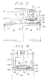
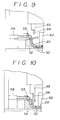
- Figures 5 through 10 are sectional views showing the operation of the bonding device.
- an automotive sun-visor 10 fabricated with the bonding device according to the present invention is prepared by covering front surfaces of a pair of core members 20 fabricated as injection molded shells of synthetic resin material with surface skin members 30, and securely attaching the core members 20 to each other at their reverse surfaces and along their edges so that the sun-visor may be made highly light-weight with a desired shock absorbing capability.
- this sun-visor requires the peripheral part of the surface skin member 30 to be folded over the edge of the core member 20 and secured onto the reverse surface thereof so as to define an aesthetically acceptable parting line 31.
- this bonding device is provided with a bonding station 40 for bonding the surface skin member 30 onto the surface of the core member 20, and a peripheral part folding back station 50 for folding back a peripheral part of the surface skin member 30 onto the reverse surface of the core member 20, the two stations being arranged one next to the other.
- the bonding station 40 is provided with a lower die 42 secured on a lower table 41 for mounting the surface skin member 30 thereon, and this lower die 42 is made of a block of resilient material such as foamed polyurethane defining a flat mounting surface.
- the peripheral part folding back station 50 is likewise provided with a lower die 52 made of synthetic resin or aluminum secured on a lower table 51 for mounting the sun-visor assembly thereon, and a plurality of slide bars 53 connected to respective drive cylinders 54.
- the slide bars 53 are used for provisionally forming the peripheral part of the surface skin member 30 in conformity with the reverse surface of the core member 20.
- An upper table 60 is provided between the bonding station 40 and the peripheral part folding back station 50 so as to be reciprocated therebetween.
- the upper table 60 is connected to a slider 71 which laterally slides over a conveying rail 70 as seen in the drawing, and the upper table 60 is provided with a drive cylinder 61 for vertically moving the upper table 60, and an upper die 62 for mounting the core member 20 thereon.
- the upper die 62 is provided with vacuum suction holes 63 for retaining the core member 20 thereon.
- the vertically moveable bars 64 are provided slightly inwardly of the periphery of the upper die 62, and are vertically actuated by drive cylinders 65 for pressing the peripheral part of the surface skin member 30 against the reverse surface of the core member 20.
- the bonding device for a surface skin member according to the present invention is constructed as described above, and the operation thereof is now described in the following with reference to Figures 5 through 10.
- the surface skin member 30 is mounted on the upper surface of the lower die 42 in the bonding station 40, and the core member 20 is mounted on the upper die 62 positioned on the side of the bonding station 40 as shown in the drawing.
- Vacuum suction is applied to the upper die 62 via the vacuum suction holes 63 so that the core member 20 may be retained on the upper die 62 by suction, and the front surface and the peripheral part of the reverse surface of the core member 20 are coated with a bonding agent.
- the drive cylinder 61 is activated so that the upper table 60 may be lowered until the upper die 62 is received by the lower die 42, and the surface skin member 30 may be bonded onto the front surface of the core member 20. Since the mounting surface of the lower die 42 is flat, the surface skin member 30 may be favorably conformed to the curved contour of the core member 20 thanks to the elasticity of the resilient material of the lower die 42 without creating any creases in the surface skin member 30.
- the upper table 60 is raised to its original position by the actuation of the drive cylinder 61.
- the slider 71 is slid along the rail 70 until the upper table 60 reaches the peripheral part folding back station 50 as illustrated in Figure 7.
- the upper table 60 is lowered by the actuation of the drive cylinder 61 as illustrated in Figure 8 to mount the half-finished product on the lower die 52 in the peripheral part folding back station 50.
- the core member 20 integrally joined with the surface skin member 30 is mounted on the lower die 52 as illustrated in Figure 9, and the slide bars 53 arranged around the lower die 52 are slid in the direction indicated by the arrow in the drawing by activating the hydraulic cylinders 54 to carry out a preliminary shaping process for the peripheral part of the surface skin member 30 by pressing it inwardly.
- the vertically moveable bars 64 are lowered by the cylinders 65 for vertical movement to press the peripheral part of the surface skin member 30, which has been subjected to the preliminary shaping process, for a certain time period against the reverse surface of the core member 20 as illustrated in Figure 10.
- the slide bars 53 and the vertically moveable bars 64 are retracted to their original positions.
- the above described embodiment was directed to the process of bonding the peripheral part of the surface skin member 30 onto the resin core member 20 of an automotive sun-visor 10, but the present invention is not limited to this application and can be applied to any other interior components such as door trims, rear corner trims or other interior component as long as the peripheral part of a surface skin member is required to be folded back onto the reverse surface of the core member.
- the bonding device for a surface skin member of a vehicle interior component offers the following specific advantages.
Landscapes
- Engineering & Computer Science (AREA)
- Manufacturing & Machinery (AREA)
- Lining Or Joining Of Plastics Or The Like (AREA)
- Vehicle Interior And Exterior Ornaments, Soundproofing, And Insulation (AREA)
Applications Claiming Priority (2)
| Application Number | Priority Date | Filing Date | Title |
|---|---|---|---|
| JP74441/91 | 1991-09-17 | ||
| JP1991074441U JP2513142Y2 (ja) | 1991-09-17 | 1991-09-17 | 内装部品における表皮材の貼着装置 |
Publications (2)
| Publication Number | Publication Date |
|---|---|
| EP0533311A1 true EP0533311A1 (de) | 1993-03-24 |
| EP0533311B1 EP0533311B1 (de) | 1996-09-25 |
Family
ID=13547326
Family Applications (1)
| Application Number | Title | Priority Date | Filing Date |
|---|---|---|---|
| EP92303594A Expired - Lifetime EP0533311B1 (de) | 1991-09-17 | 1992-04-22 | Vorrichtung für Klebeverbindungen und Verbindungsverfahren zur Herstellung von Innenbauteilen |
Country Status (4)
| Country | Link |
|---|---|
| US (2) | US5431768A (de) |
| EP (1) | EP0533311B1 (de) |
| JP (1) | JP2513142Y2 (de) |
| DE (1) | DE69214074T2 (de) |
Cited By (5)
| Publication number | Priority date | Publication date | Assignee | Title |
|---|---|---|---|---|
| EP0603498A1 (de) * | 1992-12-23 | 1994-06-29 | R + S STANZTECHNIK GmbH | Verfahren und Vorrichtung zum Umfalten von den Rändern einer laminierten Platte längs seiner Kontur zum Formen eines Bekleidungspanels |
| EP0629487A1 (de) * | 1993-06-04 | 1994-12-21 | Battenfeld GmbH | Verfahren und Vorrichtung zum Herstellen von laminierten Kunststoff-Formteilen |
| US5851569A (en) * | 1996-12-03 | 1998-12-22 | Mexican Industries Of Michigan, Inc. | Cold edge folding apparatus for making door inserts for automobile doors |
| CN105818368A (zh) * | 2015-01-09 | 2016-08-03 | 臻越自动化技术(上海)有限公司 | 车门上饰板包边装置 |
| DE102017124286A1 (de) | 2017-10-18 | 2019-04-18 | International Automotive Components Group Gmbh | Verfahren und Vorrichtung zur Herstellung eines Umbugs |
Families Citing this family (8)
| Publication number | Priority date | Publication date | Assignee | Title |
|---|---|---|---|---|
| US5925207A (en) * | 1991-01-16 | 1999-07-20 | Kasai Kogyo Co., Ltd. | Automotive interior components, and method and device for manufacturing the same |
| AU678544B3 (en) * | 1996-09-25 | 1997-05-29 | Proform N.Z. Ltd | Laminating means |
| US6101738A (en) * | 1998-07-27 | 2000-08-15 | Gleason; Gary | Sludge dewatering system and method |
| US6171428B1 (en) * | 1999-09-03 | 2001-01-09 | Dongseo Kiyeon Co., Ltd. | Method for fabricating automotive door trims |
| DE10345812A1 (de) * | 2003-09-30 | 2005-04-28 | Michael Greidenweis | Kaschierverfahren und Kaschiervorrichtung |
| DE102011015818A1 (de) * | 2011-04-01 | 2012-10-04 | Faurecia Innenraum Systeme Gmbh | Umbugverfahren, Umbugvorrichtung sowie Bauteil mit Umbug |
| KR102036129B1 (ko) * | 2019-06-03 | 2019-10-25 | 덕양산업 주식회사 | 감싸기 금형장치와 이를 이용한 내장재 제조방법 |
| KR102036132B1 (ko) * | 2019-06-03 | 2019-10-25 | 덕양산업 주식회사 | 감싸기 금형장치와 이를 이용한 내장재 제조방법 |
Citations (5)
| Publication number | Priority date | Publication date | Assignee | Title |
|---|---|---|---|---|
| GB2106831A (en) * | 1981-09-24 | 1983-04-20 | Kiss G H | A process for lining moulded articles and apparatus for performing the process |
| GB2195940A (en) * | 1986-10-03 | 1988-04-20 | Polistock Nv | Molding laminated panels |
| EP0295068A2 (de) * | 1987-06-08 | 1988-12-14 | Prince Corporation | Sonnenblende |
| FR2626211A1 (fr) * | 1988-01-27 | 1989-07-28 | Boxetui Sarl | Procede de gainage automatique et machine pour sa mise en oeuvre |
| WO1990000519A1 (fr) * | 1988-07-13 | 1990-01-25 | Christian Guilhem | Procede et dispositif pour l'habillage d'un objet au moyen d'au moins une piece souple |
Family Cites Families (26)
| Publication number | Priority date | Publication date | Assignee | Title |
|---|---|---|---|---|
| US2458864A (en) * | 1945-01-01 | 1949-01-11 | John D Lindsay | Method of making integral molded structures |
| US2500895A (en) * | 1946-09-23 | 1950-03-14 | Nat Automotive Fibres Inc | Apparatus for making trim panels |
| US2808099A (en) * | 1954-12-21 | 1957-10-01 | Silverman Jacob | Machine for folding ornamental sheet about a base |
| US3089536A (en) * | 1960-06-15 | 1963-05-14 | Chris Craft Ind Inc | Combination edge turining and welding die |
| US3147172A (en) * | 1960-08-10 | 1964-09-01 | American Motors Corp | Apparatus for folding edges of flexible covering material about a board or panel |
| US3230133A (en) * | 1962-07-13 | 1966-01-18 | Motor Coils Mfg Company | Apparatus for wrapping a sheet of material around an elongated article |
| US3383262A (en) * | 1962-10-04 | 1968-05-14 | Us Plywood Champ Papers Inc | Panel edge covering |
| US3580770A (en) * | 1967-01-31 | 1971-05-25 | Tripro Inc | Method for producing laminated structures |
| LU60972A1 (de) * | 1969-05-31 | 1970-08-04 | ||
| US3753831A (en) * | 1970-08-28 | 1973-08-21 | Boston Machine Works Co | Folding apparatus |
| US4059477A (en) * | 1976-05-26 | 1977-11-22 | Labelette Company | Box end labeling apparatus |
| US4016025A (en) * | 1976-06-29 | 1977-04-05 | Peterson Everett A | Electronic sealing apparatus |
| US4406729A (en) * | 1981-11-04 | 1983-09-27 | Evans Rotork, Inc. | Round edge former |
| US4728383A (en) * | 1982-11-10 | 1988-03-01 | Audi Ag. | Method of mounting ready-made headliners into bodies of automotive vehicles |
| FR2546635B1 (fr) * | 1983-05-25 | 1986-07-04 | Saint Gobain Vitrage | Procede et dispositif pour recouvrir une ebauche d'un verre de lunettes par une feuille de protection |
| JPS60131225A (ja) * | 1983-12-20 | 1985-07-12 | Toshio Nishino | 平板状芯材を熱可塑性合成樹脂フイルム等を以てくるむ法 |
| JPH01275124A (ja) * | 1988-04-28 | 1989-11-02 | Ishikawajima Harima Heavy Ind Co Ltd | 表皮材貼付方法及びその装置 |
| US5176777A (en) * | 1988-07-13 | 1993-01-05 | Christian Guilhem | Process and apparatus for covering an object with at least one piece of flexible material |
| JPH072378B2 (ja) * | 1988-09-27 | 1995-01-18 | 池田物産株式会社内 | 車両用成形天井の表皮端末処理装置 |
| JPH0292636A (ja) * | 1988-09-30 | 1990-04-03 | Wakaba Sangyo:Kk | 軟質シート被覆物品の製造方法 |
| US5000805A (en) * | 1989-04-28 | 1991-03-19 | Hoover Universal, Inc. | Method for vacuum forming composite vehicle seat |
| US5108529A (en) * | 1989-09-05 | 1992-04-28 | Shuert Lyle H | Method of forming a twin sheet plastic pallet using preforming |
| US5139604A (en) * | 1990-05-09 | 1992-08-18 | Mitchell Charles P | Controlled bladder wrap tool system |
| US5258083A (en) * | 1990-10-18 | 1993-11-02 | Westinghouse Electric Corp. | Method for constructing an office space dividing panel |
| JP2558014B2 (ja) * | 1991-01-16 | 1996-11-27 | 河西工業株式会社 | 自動車用内装部品の製造方法 |
| US5264058A (en) * | 1992-08-24 | 1993-11-23 | Monsanto | Forming a shaped prelaminate and bilayer glazing of glass and plastic |
-
1991
- 1991-09-17 JP JP1991074441U patent/JP2513142Y2/ja not_active Expired - Lifetime
-
1992
- 1992-04-22 EP EP92303594A patent/EP0533311B1/de not_active Expired - Lifetime
- 1992-04-22 DE DE69214074T patent/DE69214074T2/de not_active Expired - Fee Related
-
1993
- 1993-07-28 US US08/097,929 patent/US5431768A/en not_active Expired - Fee Related
-
1994
- 1994-12-06 US US08/348,899 patent/US5609709A/en not_active Expired - Fee Related
Patent Citations (5)
| Publication number | Priority date | Publication date | Assignee | Title |
|---|---|---|---|---|
| GB2106831A (en) * | 1981-09-24 | 1983-04-20 | Kiss G H | A process for lining moulded articles and apparatus for performing the process |
| GB2195940A (en) * | 1986-10-03 | 1988-04-20 | Polistock Nv | Molding laminated panels |
| EP0295068A2 (de) * | 1987-06-08 | 1988-12-14 | Prince Corporation | Sonnenblende |
| FR2626211A1 (fr) * | 1988-01-27 | 1989-07-28 | Boxetui Sarl | Procede de gainage automatique et machine pour sa mise en oeuvre |
| WO1990000519A1 (fr) * | 1988-07-13 | 1990-01-25 | Christian Guilhem | Procede et dispositif pour l'habillage d'un objet au moyen d'au moins une piece souple |
Non-Patent Citations (1)
| Title |
|---|
| PATENT ABSTRACTS OF JAPAN vol. 014, no. 287 (M-0988)21 June 1990 & JP-A-20 89 618 ( IKEDA BUSSAN CO LTD ) * |
Cited By (8)
| Publication number | Priority date | Publication date | Assignee | Title |
|---|---|---|---|---|
| EP0603498A1 (de) * | 1992-12-23 | 1994-06-29 | R + S STANZTECHNIK GmbH | Verfahren und Vorrichtung zum Umfalten von den Rändern einer laminierten Platte längs seiner Kontur zum Formen eines Bekleidungspanels |
| WO1995035197A1 (en) * | 1992-12-23 | 1995-12-28 | Kodama Chemical Industry Co., Ltd. | Method and apparatus for folding a brim of a laminated panel around a panel rim to form a trim panel |
| EP0629487A1 (de) * | 1993-06-04 | 1994-12-21 | Battenfeld GmbH | Verfahren und Vorrichtung zum Herstellen von laminierten Kunststoff-Formteilen |
| US5851569A (en) * | 1996-12-03 | 1998-12-22 | Mexican Industries Of Michigan, Inc. | Cold edge folding apparatus for making door inserts for automobile doors |
| CN105818368A (zh) * | 2015-01-09 | 2016-08-03 | 臻越自动化技术(上海)有限公司 | 车门上饰板包边装置 |
| CN105818368B (zh) * | 2015-01-09 | 2017-12-12 | 臻越自动化技术(上海)有限公司 | 车门上饰板包边装置 |
| DE102017124286A1 (de) | 2017-10-18 | 2019-04-18 | International Automotive Components Group Gmbh | Verfahren und Vorrichtung zur Herstellung eines Umbugs |
| EP3473409A2 (de) | 2017-10-18 | 2019-04-24 | International Automotive Components Group GmbH | Verfahren und vorrichtung zur herstellung eines umbugs |
Also Published As
| Publication number | Publication date |
|---|---|
| DE69214074D1 (de) | 1996-10-31 |
| EP0533311B1 (de) | 1996-09-25 |
| JP2513142Y2 (ja) | 1996-10-02 |
| US5431768A (en) | 1995-07-11 |
| DE69214074T2 (de) | 1997-05-15 |
| JPH0526348U (ja) | 1993-04-06 |
| US5609709A (en) | 1997-03-11 |
Similar Documents
| Publication | Publication Date | Title |
|---|---|---|
| US5609709A (en) | Bonding process for fabricating an interior component | |
| EP0720902B1 (de) | Vorrichtung und Verfahren zum Formen einer mehrschichtigen Verkleidingskomponente | |
| US5718791A (en) | Method of laminating a trim panel and folding a cover sheet edge around the panel rim | |
| US6706370B1 (en) | Sunshade of a sunroof for a motor vehicle and manufacturing method thereof | |
| EP0732182A2 (de) | Verfahren zum Formen eines mehrschichtigen Formteils | |
| US5236534A (en) | Method for fabricating automotive door trims | |
| US5968437A (en) | Method for integrally molding a thermoplastic laminated assembly | |
| US5290093A (en) | Method of seam location using vacuum | |
| JPS63132026A (ja) | 貼合せ成形品及びその成形方法 | |
| JP2503494Y2 (ja) | 自動車用内装部品における装飾シ―トの圧着装置 | |
| DE3030537A1 (de) | Vorrichtung zum beschichten einer werkstueckoberflaeche mit einer tiefziehfaehigen folie | |
| JPS6211657B2 (de) | ||
| JPH08258132A (ja) | 表皮材の貼着方法及びその貼着装置 | |
| JPS5921306B2 (ja) | 積層樹脂成形品の貼着加工方法 | |
| JPH04341823A (ja) | 自動車用内装部品における装飾シートの圧着方法および圧着装置 | |
| JP2876238B2 (ja) | 表装部材の端末処理方法 | |
| JPH0528983B2 (de) | ||
| JPH02206513A (ja) | 自動車用内装部品の製造方法 | |
| JP2610323B2 (ja) | 成形装置 | |
| JP2823107B2 (ja) | 内装部品における装飾シートの圧着方法および圧着装置 | |
| JPS57193315A (en) | Treating method for end of bonded formed product | |
| JPH0885123A (ja) | 自動車用内装部品における装飾シートの圧着方法 | |
| JPH04128827U (ja) | プレス成形用金型装置 | |
| JP3915206B2 (ja) | 積層体の製造方法 | |
| JP2782613B2 (ja) | 内装材の製造方法 |
Legal Events
| Date | Code | Title | Description |
|---|---|---|---|
| PUAI | Public reference made under article 153(3) epc to a published international application that has entered the european phase |
Free format text: ORIGINAL CODE: 0009012 |
|
| 17P | Request for examination filed |
Effective date: 19920505 |
|
| AK | Designated contracting states |
Kind code of ref document: A1 Designated state(s): DE FR GB SE |
|
| 17Q | First examination report despatched |
Effective date: 19950331 |
|
| GRAH | Despatch of communication of intention to grant a patent |
Free format text: ORIGINAL CODE: EPIDOS IGRA |
|
| GRAA | (expected) grant |
Free format text: ORIGINAL CODE: 0009210 |
|
| GRAH | Despatch of communication of intention to grant a patent |
Free format text: ORIGINAL CODE: EPIDOS IGRA |
|
| AK | Designated contracting states |
Kind code of ref document: B1 Designated state(s): DE FR GB SE |
|
| REF | Corresponds to: |
Ref document number: 69214074 Country of ref document: DE Date of ref document: 19961031 |
|
| ET | Fr: translation filed | ||
| PG25 | Lapsed in a contracting state [announced via postgrant information from national office to epo] |
Ref country code: GB Effective date: 19970422 |
|
| PG25 | Lapsed in a contracting state [announced via postgrant information from national office to epo] |
Ref country code: SE Effective date: 19970423 |
|
| PLBE | No opposition filed within time limit |
Free format text: ORIGINAL CODE: 0009261 |
|
| STAA | Information on the status of an ep patent application or granted ep patent |
Free format text: STATUS: NO OPPOSITION FILED WITHIN TIME LIMIT |
|
| 26N | No opposition filed | ||
| GBPC | Gb: european patent ceased through non-payment of renewal fee |
Effective date: 19970422 |
|
| PG25 | Lapsed in a contracting state [announced via postgrant information from national office to epo] |
Ref country code: FR Free format text: LAPSE BECAUSE OF NON-PAYMENT OF DUE FEES Effective date: 19971231 |
|
| PG25 | Lapsed in a contracting state [announced via postgrant information from national office to epo] |
Ref country code: DE Free format text: LAPSE BECAUSE OF NON-PAYMENT OF DUE FEES Effective date: 19980101 |
|
| EUG | Se: european patent has lapsed |
Ref document number: 92303594.3 |
|
| REG | Reference to a national code |
Ref country code: FR Ref legal event code: ST |