EP0532934A1 - Device for the gripper conversion of the gripper cylinder of the turning device of a rotary perfecting printing press for sheets - Google Patents
Device for the gripper conversion of the gripper cylinder of the turning device of a rotary perfecting printing press for sheets Download PDFInfo
- Publication number
- EP0532934A1 EP0532934A1 EP92114282A EP92114282A EP0532934A1 EP 0532934 A1 EP0532934 A1 EP 0532934A1 EP 92114282 A EP92114282 A EP 92114282A EP 92114282 A EP92114282 A EP 92114282A EP 0532934 A1 EP0532934 A1 EP 0532934A1
- Authority
- EP
- European Patent Office
- Prior art keywords
- gripper cylinder
- gripper
- shaft
- switching
- control shaft
- Prior art date
- Legal status (The legal status is an assumption and is not a legal conclusion. Google has not performed a legal analysis and makes no representation as to the accuracy of the status listed.)
- Granted
Links
Images


Classifications
-
- B—PERFORMING OPERATIONS; TRANSPORTING
- B41—PRINTING; LINING MACHINES; TYPEWRITERS; STAMPS
- B41F—PRINTING MACHINES OR PRESSES
- B41F21/00—Devices for conveying sheets through printing apparatus or machines
- B41F21/10—Combinations of transfer drums and grippers
- B41F21/106—Combinations of transfer drums and grippers for reversing sheets, e.g. for perfecting machine
Definitions
- the invention relates to a device for converting the gripper control on a gripper cylinder of a turning device in a sheet-fed rotary printing press for face and back printing with training features according to the preamble of patent claim 1.
- Such a device is described in DE-PS 38 14 831.
- the adjusting ring gear is rotatably arranged on a pin attachment of the fixed gear on the gripper cylinder.
- the clamping device consists of a pressure plate anchored to the fixed gear, from a plurality of radially directed pressure levers, which are supported with their outer end against the adjusting ring and in the vicinity of these ends on the opposite side against the pressure plate, and from a prestressed spring, so that their reaction force Causes clamping forces.
- This spring is clamped between a disc and a collar on the spring axially penetrating push rod, so that the action of the reaction forces of the prestressed spring by shifting the disc on the push rod to release the clamp and ineffective to produce the clamp.
- the push rod actuates during its axial displacement under the action of the reaction forces of the spring with its end directed towards the center of the machine one arm of an angular lever pivotably mounted in a recess in the gripper cylinder about an axis lying transversely to the push rod, the other arm of which engages under a clamping bracket which extends radially to Axis of the gripper cylinder transmits tensile forces acting on the switching bridge, by moving them parallel to the axis of the gripper cylinder, the gripper control is changed.
- the reaction forces of the spring for clamping the adjusting ring gear and the fixed gear also act as clamping forces between the switching bridge for the changeover of the gripper control, but here in the radial direction, so that this is monitored by the same securing elements.
- a switching shaft is rotatably mounted with its end facing the machine center over the end of the push rod and a recess enabling the placement of the angle lever extends and is rotatably coupled in a further recess by an angular gear from a pair of bevel gears with an eccentric mounted in a diametrically extending bore, which in turn engages in a link formed on the switching bridge, so that a rotary movement of the switching shaft in a linear displacement of the switching bridge is implemented.
- a manual operation with a key is provided, which is attached to a key head through a recess in the Pressure plate can be placed on the drive side leading end of the control shaft.
- a simplified drive arrangement for the adjustment movement of a shift shaft mounted centrally in the gripper cylinder is known from JP-Sho 63-53037, but a centrally acting clamping device is missing.
- the adjusting ring gear and the fixed gear are frictionally clamped together by several screws in this known arrangement.
- the object of the invention is to provide a simplified, space-saving design and a reduction in the recesses weakening the strength of the gripper cylinder.
- the invention solves this problem by training with the features of claim 1.
- the feature that stands out is that the gripper cylinder and its bearing journal on the drive side only have a central, axially extending bore with a relatively small cross section for receiving a control shaft that is effective both for clamping as a push rod and for the changeover.
- the advantages known from arrangements according to the prior art mentioned remain unrestricted.
- the single shaft enables the clamping of the adjusting ring gear with the fixed gear under a predeterminable reaction force of a spring that is retained with each changeover, the transmission of this reaction force to the clamping connection points of the switching bridge with the gripper cylinder and also the automatic changeover of the gripper control during the angular adjustment between the adjusting ring gear and the Fixed gear.
- reaction force of the spring for the clamping can optionally be transferred to several clamping points of the switching bridge.
- a special inventive concept is contained in claim 5.
- the proposed axial curve for implementation the rotary movement of the selector shaft when changing to a linear movement for moving the switching bridge is particularly simple and robust. It enables the axial switching path to be limited in a simple manner, regardless of the size of the angular adjustment of the adjusting ring gear relative to the fixed gear.
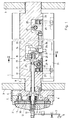
- the gripper cylinder 1 of the turning device of a sheet-fed rotary printing machine for perfecting is mounted on both sides with a bearing pin 2 of reduced diameter in the side part 3 of the machine frame. Outside of this side part 3, a fixed gear 4 is firmly connected to the end face of the bearing journal 2 by screws 5.
- an adjusting ring gear 7 is arranged concentrically about the axis 8 of the gripper cylinder 1 concentrically with the fixed gear 4.
- the frictional clamping connection between the adjusting ring gear 7 and the fixed gear 4 takes place through the reaction force of a spring 9, which is clamped between a radial projection on a switching shaft 10 penetrating the spring axially with radial play and an axially sliding disc 11 on the latter.
- a pressure ring 14 which cooperates with a threaded sleeve 15, which can be screwed onto a threaded pin at the free end of the control shaft 10 and in turn cooperates with a switching element 16 in the drive circuit of the machine, such that the threaded sleeve 15 only on the pressure ring 14 can act when the switching element 16 actuated via a rocker 17 has interrupted the drive circuit and a closing of this circuit is only possible when the spring 9 is connected the full reaction force acts on the elements of the clamp.
- the switching element 16 By screwing the threaded sleeve 15 on the threaded pin on the control shaft 10, the switching element 16 is first actuated before the threaded sleeve acts on the pressure ring and this presses the disk 11 with further prestressing of the spring 9 in the direction against the projecting collar on the control shaft 10, so that the pressure lever 12 are relieved and the clamping between the adjusting ring gear 7 and the fixed gear 4 is released.
- a screwing of the threaded sleeve 15 in the opposite direction initially has the result that the disc 11 is pressed under the action of the spring 9 against the inner ends of the pressure lever 12, and only after the reaction force of the spring is fully effective against the ends of the pressure lever 12 forms there is a space between the pressure ring 14 and the threaded sleeve 15 before the switching element 16 is released for the drive circuit via the rocker 17.
- the selector shaft 10 is axially limited movable in the gripper cylinder 1 and presses with an annular shoulder 18 against one arm of an angle lever 19 which is pivotally mounted about an axis 20 transverse to the axis 8 in a recess 21 of the gripper cylinder 1 and with the other Arm engages under a clamping bracket 22, which is connected by tension bolts 23 to the switching bridge 24, which is linearly displaceable approximately parallel to the axis 8 for gripper changeover.
- the angle lever 19 is mounted in a slide 25 which is carried out to the other end of the gripper cylinder 1 and here acts against a pendulum body 27 mounted in a recess 26, which in turn also engages under a clamping bracket 28 which is connected to the switching bridge by means of draw bolts 29 24 is connected.
- the reaction forces of the spring 9 are simultaneously effective as radial forces acting in the direction of the axis 8 for the switching bridge, so that a frictional Clamp connection between the switching bridge and the gripper cylinder is created.
- a switching wheel 30 is fastened on the drive side outside of the side part 3 on the switching shaft 10, which at the same time forms the collar projection of the switching shaft 10 for the engagement of the spring 9.
- the toothing of an idler gear 31 engages in the external toothing of this ratchet wheel 30, which on the other hand meshes with an internal toothing on the adjusting sprocket 7, so that an angular rotation of the adjusting sprocket 7 relative to the fixed gear 4 leads to a rotary movement of the selector shaft 10.
- the end of the control shaft 10 directed towards the middle of the machine passes through a bore 33 in the arm of the angle lever 19 following the annular shoulder 18 with a section of reduced diameter.
- the extension 32 is continued beyond the angle lever 19 into a recess 34.
- the free end of the extension 32 engages in a rotationally fixed but axially movable manner in a journal of an axial curve 36, which is rotatably supported with this journal in a bearing 35 in the gripper cylinder 2, so that axial movements of the control shaft 10 relative to the axial curve 36 enable the clamping .
- a pin 37 of the switching bridge 24 engages radially in the axial curve 36, so that a rotation of the axial curve 36 results in a linear displacement of the switching bridge 24.
- a roller 37a is advantageously mounted on the pin 37 in order to reduce the frictional resistances.
- the axial slope of the curve 36 extends only over a changeover angle corresponding to the axial changeover movement for the gripper control, so that an axial movement component is only transmitted to the switching bridge 24 in this angular range when the adjusting ring gear 7 is adjusted relative to the fixed gearwheel 4.
- the pin 37 extends through an elongated hole 38 in the slide 25, around the latter linear movement in the clamping and in the release of the clamping not to hinder.
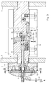
- the design and mounting of the gripper cylinder 1 and the elements of the clamping between the adjusting ring gear 7 and the fixed gear 4 correspond to the description of FIG. 1.
- the elements for converting the rotary movement of the control shaft 10 into an axial movement are different the switching bridge 24.
- a bearing pin of a bevel gear 39 is rotatably mounted in the bearing 35.
- the end of the selector shaft 10 engages in the bearing journal of this bevel gear 39 in a rotationally fixed but axially movable manner.
- the bevel gear 39 engages in the toothing of a bevel gear 40, which is attached to the shaft 41, which is mounted with its axis transverse to the axis 8 of the control shaft 10 in the gripper cylinder and carries an eccentric 42 at its free end, which engages with an eccentric roller 42a mounted eccentrically to the axis of the shaft 41 in a link 43 which is assigned to the switching bridge 24.
- a rotary movement of the selector shaft 10 also causes an axial displacement movement of the switching bridge 24.
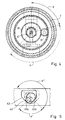
- the link 43 has a special shape, such as, for example is shown in Figure 5.
- the backdrop 43 has two straight buttons 43a and 43b, which enclose each other approximately at a right angle, one of which 43a is assigned to the straight print and the other 43b to the reverse pressure. Both buttons 43a and 43b affect the imaginary circular arc, which the outer vertex of the eccentric 42 strikes when it rotates about the axis of the shaft 41, so that they define the changeover angle x1 from face pressure to back pressure and vice versa, which is due to the transmission ratio of the gears 30 and 31 and the Internal toothing of the adjusting ring gear 7 results. Outside of these buttons 43a and 43b, i.e. outside the changeover angle x1, the eccentric 42 moves in a free space, so that during the adjustment of the adjusting ring gear 7 relative to the fixed gear 4 in the format adjustment range y (y1) there is no displacement movement of the switching bridge 24.
- FIGS. 6 to 9 execution examples for elements for stopping a gripper shaft 44 during the adjustment of the adjusting ring gear 7 relative to the fixed gear 4 are shown.
- a radial curve 45 is fastened on the selector shaft 10 and blocks a parking cam 48 on the gripper shaft 44 via a roller 46 on an angle lever 47.
- a comparable result can also be achieved according to the example of FIGS. 8 and 9 by a pair of gearwheels 49 and 50, of which one 49 is fastened on the selector shaft 10 and the other 50 has a stop bar 51 which also has a stop cam in a predetermined angular position 48 blocked on the Grelferwelle 44.
Abstract
Description
Die Erfindung betrifft eine Vorrichtung zur Umstellung der Greifersteuerung an einem Greiferzylinder einer Wendeeinrichtung in einer Bogenrotationsdruckmaschine für den Schön- und Widerdruck mit Ausbildungsmerkmalen nach dem Oberbegriff des Patentanspruches 1.The invention relates to a device for converting the gripper control on a gripper cylinder of a turning device in a sheet-fed rotary printing press for face and back printing with training features according to the preamble of
Eine derartige Vorrichtung ist in der DE-PS 38 14 831 beschrieben. Bei dieser bekannten Einrichtung ist der Verstellzahnkranz auf einem Zapfenansatz des Festzahnrades an dem Greiferzylinder verdrehbar angeordnet. Die Klemmvorrichtung besteht aus einer am Festzahnrad verankerten Druckplatte, aus mehreren radial gerichteten Druckhebeln, die sich mit ihrem äußeren Ende gegen den Verstellkranz und in Nähe dieser Enden auf der gegenüberliegenden Seite gegen die Druckplatte abstützen, und aus einer vorgespannten Feder, so daß deren Reaktionskraft die Klemmkräfte hervorruft. Diese Feder ist zwischen einer Scheibe und einem Bund an der die Feder axial durchgreifenden Druckstange eingespannt, so daß die Wirkung der Reaktionskräfte der vorgespannten Feder durch Verschiebung der Scheibe auf der Druckstange zum Lösen der Klemmung unwirksam und zur Herstellung der Klemmung wirksam werden. Zu dieser Verschiebung dient ein auf der Druckstange verschraubbares Betätigungsorgan, welches gleichzeitig ein Sicherungsglied im elektrischen Stromkreis der Maschine betätigt, so daß der Stromkreis der Maschine unterbrochen wird, bevor die Klemmung gelöst werden kann, und erst wieder zu schließen ist, wenn die Klemmung wieder hergestellt ist. Die Druckstange betätigt bei ihrer axialen Verschiebung unter der Wirkung der Reaktionskräfte der Feder mit ihrem zur Maschinenmitte gerichteten Ende den einen Arm eines in einer Ausnehmung im Greiferzylinder um eine quer zur Druckstange liegende Achse schwenkbar gelagerten Winkelhebel, dessen anderer Arm einen Klemmbügel untergreift, der radial zur Achse des Greiferzylinders wirkende Zugkräfte auf die Schaltbrücke überträgt, durch deren Verschiebung parallel zur Achse des Greiferzylinders die Umstellung der Greifersteuerung erfolgt. Somit wirken die Reaktionskräfte der Feder für die Klemmung des Verstellzahnkranzes und des Festzahnrades auch als Klemmkräfte zwischen der Schaltbrücke für die Umstellung der Greifersteuerung, hier jedoch in radialer Richtung, so daß diese durch die gleichen Sicherungselemente überwacht wird.Such a device is described in DE-PS 38 14 831. In this known device, the adjusting ring gear is rotatably arranged on a pin attachment of the fixed gear on the gripper cylinder. The clamping device consists of a pressure plate anchored to the fixed gear, from a plurality of radially directed pressure levers, which are supported with their outer end against the adjusting ring and in the vicinity of these ends on the opposite side against the pressure plate, and from a prestressed spring, so that their reaction force Causes clamping forces. This spring is clamped between a disc and a collar on the spring axially penetrating push rod, so that the action of the reaction forces of the prestressed spring by shifting the disc on the push rod to release the clamp and ineffective to produce the clamp. An actuator that can be screwed onto the push rod, which simultaneously actuates a securing element in the electrical circuit of the machine, serves for this displacement, so that the circuit of the machine is interrupted is before the clamp can be released and only close again when the clamp is restored. The push rod actuates during its axial displacement under the action of the reaction forces of the spring with its end directed towards the center of the machine one arm of an angular lever pivotably mounted in a recess in the gripper cylinder about an axis lying transversely to the push rod, the other arm of which engages under a clamping bracket which extends radially to Axis of the gripper cylinder transmits tensile forces acting on the switching bridge, by moving them parallel to the axis of the gripper cylinder, the gripper control is changed. Thus, the reaction forces of the spring for clamping the adjusting ring gear and the fixed gear also act as clamping forces between the switching bridge for the changeover of the gripper control, but here in the radial direction, so that this is monitored by the same securing elements.
Zur Durchführung der Umstellung durch eine lineare Verschiebung der Schaltbrücke parallel zur Achse des Greiferzylinders ist bei der bekannten Anordnung parallel zur Druckstange in einer weiteren achsparallel verlaufenden Bohrung in dem Greiferzylinder eine Schaltwelle drehbar gelagert, die mit ihrem zur Maschinenmitte gerichteten Ende über das Ende der Druckstange und einer die Unterbringung des Winkelhebels ermöglichenden Ausnehmung hinausreicht und in einer weiteren Ausnehmung durch ein Winkelgetriebe aus einem Kegelradpaar mit einem in einer diametral verlaufenden Bohrung gelagerten Exzenter drehfest gekuppelt ist, der seinerseits in eine an der Schaltbrücke ausgebildete Kulisse eingreift, so daß eine Drehbewegung der Schaltwelle in eine lineare Verschiebung der Schaltbrücke umgesetzt wird. Für die Umstellung ist eine Handbetätigung mit einem Schlüssel vorgesehen, der auf einen Schlüsselkopf an dem durch eine Ausnehmung der Druckplatte auf der Antriebsseite herausgeführten Ende der Schaltwelle aufgesetzt werden kann.To carry out the change by a linear displacement of the switching bridge parallel to the axis of the gripper cylinder in the known arrangement parallel to the push rod in a further axis-parallel bore in the gripper cylinder, a switching shaft is rotatably mounted with its end facing the machine center over the end of the push rod and a recess enabling the placement of the angle lever extends and is rotatably coupled in a further recess by an angular gear from a pair of bevel gears with an eccentric mounted in a diametrically extending bore, which in turn engages in a link formed on the switching bridge, so that a rotary movement of the switching shaft in a linear displacement of the switching bridge is implemented. For the changeover, a manual operation with a key is provided, which is attached to a key head through a recess in the Pressure plate can be placed on the drive side leading end of the control shaft.
Eine vereinfachte Antriebsanordnung für die Verstellbewegung einer zentral in dem Greiferzylinder gelagerten Schaltwelle ist aus JP-Sho 63-53037 bekannt, jedoch fehlt eine zentral wirksame Klemmvorrichtung. Der Verstellzahnkranz und das Festzahnrad werden bei dieser bekannten Anordnung durch mehrere Schrauben reibschlüssig miteinander verspannt.A simplified drive arrangement for the adjustment movement of a shift shaft mounted centrally in the gripper cylinder is known from JP-Sho 63-53037, but a centrally acting clamping device is missing. The adjusting ring gear and the fixed gear are frictionally clamped together by several screws in this known arrangement.
Für die Verstellbewegung ist aus der DE-0S 39 11 609 eine Kopplung der Schaltwelle mit dem Verstellzahnkranz durch verzahnte Zwischenglieder bekannt, so daß die Umstellung der Greifersteuerung über die Schaltbrücke, die Schaltwelle und die verzahnten Zwischenglieder selbsttätig bei der Verstellung des Verstellzahnkranzes gegenüber dem Festzahnrad zur Umstellung der Maschine von Schön- auf widerdruck und umgekehrt erfolgt. Bekannt ist aus dieser Druckschrift auch die Ausbildung der verzahnten Zwischenglieder oder eines Mehrgelenk-Hebelgetriebes zur Kopplung des Verstellzahnkranzes mit der Schaltwelle in der weise, daß Drehkräfte nur in einem winkelbereich übertragen werden, der der Umstellung der Schaltbrücke entspricht, so daß die Formatanpassung durch eine Verstellung des Verstellzahnkranzes gegenüber dem Festzahnrad in einem wesentlich größeren Winkelbereich möglich ist.For the adjustment movement from DE-0S 39 11 609 a coupling of the selector shaft with the adjusting ring gear through toothed intermediate elements is known, so that the changeover of the gripper control via the switching bridge, the selector shaft and the toothed intermediate elements automatically when adjusting the adjusting ring gear relative to the fixed gear The machine is switched from beautiful to reverse pressure and vice versa. It is also known from this document the design of the toothed intermediate links or a multi-link lever mechanism for coupling the adjusting ring gear to the selector shaft in such a way that rotational forces are only transmitted in an angular range which corresponds to the changeover of the switching bridge, so that the format adjustment by adjustment of the adjusting ring gear is possible in a much larger angular range compared to the fixed gear.
Eine Anordnung zur übertragung der radial zur Achse des Greiferzylinders gerichteten Klemmkräfte zur reibschlüssigen Verbindung der Schaltbrücke auf dem Greiferzylinder auf mehrere in Achsrichtung des Greiferzylinders nebeneinanderliegende Klemmstellen ist aus der DE-PS 40 04 352 bekannt. Dazu werden die Lagerreaktionskräfte des Winkelhebels, gegen dessen einen Arm die Druckstange preßt, durch einen Schieber und einen Pendelkörper auf wenigstens einen weiteren Klemmbügel übertragen, so daß auch dieser bei der Klemmung durch die Reaktionskräfte der die Klemmung bewirkenden Feder belastet wird und die Schaltbrücke radial gegen den Greiferzylinder verspannt.An arrangement for transmitting the clamping forces directed radially to the axis of the gripper cylinder for the frictional connection of the switching bridge on the gripper cylinder to several clamping points lying next to one another in the axial direction of the gripper cylinder is known from DE-PS 40 04 352. For this purpose, the bearing reaction forces of the bell crank, against which one arm the pressure rod presses, transmitted by a slide and a pendulum body to at least one further clamping bracket, so that this, too, is loaded during the clamping by the reaction forces of the spring causing the clamping and clamps the switching bridge radially against the gripper cylinder.
Aufgabe der Erfindung ist die Schaffung einer vereinfachten, raumsparenden Bauweise und einer Reduzierung der die Festigkeit des Greiferzylinders schwächenden Ausnehmungen.The object of the invention is to provide a simplified, space-saving design and a reduction in the recesses weakening the strength of the gripper cylinder.
Die Erfindung löst diese Aufgabe durch eine Ausbildung mit den Merkmalen nach dem Patentanspruch 1.The invention solves this problem by training with the features of
Herausragend ist das Merkmal, daß der Greiferzylinder und sein Lagerzapfen auf der Antriebsseite nur eine zentrale, in Achsrichtung verlaufende Bohrung relativ kleinen Querschnitts zur Aufnahme einer sowohl für die Klemmung als Druckstange als auch für die Umstellung wirksame Schaltwelle aufweist. Die von Anordnungen nach dem genannten Stand der Technik her bekannten Vorteile bleiben uneingeschränkt erhalten. Die einzige Welle ermöglicht die Klemmung des Verstellzahnkranzes mit dem Festzahnrad unter einer vorbestimmbaren und bei jeder Umstellung erhaltenbleibenden Reaktionskraft einer Feder, die übertragung dieser Reaktionskraft auf die Klemmverbindungsstellen der Schaltbrücke mit dem Greiferzylinder und außerdem die selbsttätige Umstellung der Greifersteuerung bei der Winkelverstellung zwischen dem Verstellzahnkranz und dem Festzahnrad.The feature that stands out is that the gripper cylinder and its bearing journal on the drive side only have a central, axially extending bore with a relatively small cross section for receiving a control shaft that is effective both for clamping as a push rod and for the changeover. The advantages known from arrangements according to the prior art mentioned remain unrestricted. The single shaft enables the clamping of the adjusting ring gear with the fixed gear under a predeterminable reaction force of a spring that is retained with each changeover, the transmission of this reaction force to the clamping connection points of the switching bridge with the gripper cylinder and also the automatic changeover of the gripper control during the angular adjustment between the adjusting ring gear and the Fixed gear.
Erhalten bleibt auch der Vorteil, daß die Reaktionskraft der Feder für die Klemmung wahlweise auch auf mehrere Klemmstellen der Schaltbrücke übertragen werden können.There is also the advantage that the reaction force of the spring for the clamping can optionally be transferred to several clamping points of the switching bridge.
Ein besonderer Erfindungsgedanke ist in dem Anspruch 5 enthalten. Die hierin vorgeschlagene Axialkurve zur Umsetzung der Drehbewegung der Schaltwelle bei der Umstellung in eine lineare Bewegung zur Verschiebung der Schaltbrücke ist besonders einfach und robust. Sie ermöglicht in einfacher Weise die Begrenzung des axialen Schaltweges unabhängig von der Größe der Winkelverstellung des Verstellzahnkranzes gegenüber dem Festzahnrad.A special inventive concept is contained in
Weitere Besonderheiten der Erfindung enthalten die Ansprüche 2, 3 und 6 bis 9.
Ausführungsbeispiele der Erfindung sind auf der Zeichnung teils schematisch dargestellt. Es zeigen:
Figur 1- einen Schnitt in einer Achsebene durch das antriebsseitige Ende einer Wendetrommel,
Figur 2- einen Teilschnitt nach der Linie II - II der
Figur 1, Figur 3- einen Schnitt entsprechend
Figur 1 mit abgeänderter Ausbildung der übertragungsglieder, Figur 4- einen Schnitt nach der Linie IV - IV der
Figur 3, Figur 5- einen Schnitt nach der Linie V - V der
Figur 3, Figur 6- ein weiteres Ausführungsbeispiel der übertragungsglieder für die Drehbewegung der Schaltwelle auf die Greifersteuerung,
Figur 7- eine gegenüber
Figur 6 um 90° versetzte Schnittdarstellung, Figur 8- ein gegenüber den
Figuren 6 und 7 abgeändertes Ausführungsbeispiel der übertragungsglieder und Figur 9- eine gegenüber der
Figur 8 um 90° versetzte Schnittdarstellung.
- Figure 1
- 2 shows a section in an axial plane through the drive end of a turning drum,
- Figure 2
- 2 shows a partial section along the line II-II of FIG. 1,
- Figure 3
- 2 shows a section corresponding to FIG. 1 with a modified design of the transmission elements,
- Figure 4
- 4 shows a section along the line IV-IV of FIG. 3,
- Figure 5
- 4 shows a section along the line V-V of FIG. 3,
- Figure 6
- another embodiment of the transmission elements for the rotary movement of the control shaft on the gripper control,
- Figure 7
- 6 shows a sectional view offset by 90 ° compared to FIG. 6,
- Figure 8
- an modified embodiment of Figures 6 and 7 of transmission links and
- Figure 9
- a sectional view offset by 90 ° compared to FIG.
Der Greiferzylinder 1 der Wendeeinrichtung einer Bogenrotationsdruckmaschine für den Schön- und Widerdruck ist beidseitig mit einem im Durchmesser verringerten Lagerzapfen 2 im Seitenteil 3 des Maschinengestells gelagert. Außerhalb dieses Seitenteils 3 ist ein Festzahnrad 4 mit der Stirnfläche des Lagerzapfens 2 durch Schrauben 5 fest verbunden. Auf einem Zapfenansatz 6 ist konzentrisch zum Festzahnrad 4 ein Verstellzahnkranz 7 um die Achse 8 des Greiferzylinders 1 verstellbar angeordnet. Die reibschlüsslge Klemmverbindung zwischen dem Verstellzahnkranz 7 und dem Festzahnrad 4 erfolgt durch die Reaktionskraft einer Feder 9, die zwischen einem radialen Vorsprung an einer die Feder axial mit radialem Spiel durchgreifenden Schaltwelle 10 und einer auf dieser axial gleitend beweglichen Scheibe 11 eingespannt ist. Gegen die Außenseite dieser Scheibe 11 stützen sich die inneren Enden mehrerer, radial gerichteter Druckhebel 12 ab, deren äußere Enden sich gegen den Verstellzahnkranz 7 und in Nähe der äußeren Enden mit balligen oder wulstigen Erhebungen gegen eine Druckplatte 13 abstützen, so daß die freien Enden dieser Druckhebel 12 unter der Wirkung der Federreaktionskraft gegen ihre inneren Enden den Verstellzahnkranz 7 reibschlüssig fest gegen das Festzahnrad 4 pressen. Zum Lösen der Klemmung dient ein Druckring 14, der mit einer Gewindehülse 15 zusammenwirkt, die auf einem Gewindezapfen am freien Ende der Schaltwelle 10 verschraubbar ist und ihrerseits mit einem Schaltorgan 16 im Antriebsstromkreis der Maschine zusammenwirkt, derart, daß die Gewindehülse 15 erst auf den Druckring 14 einwirken kann, wenn das über eine Wippe 17 betätigte Schaltorgan 16 den Antriebsstromkreis unterbrochen hat und eine Schließung dieses Stromkreises erst möglich ist, wenn die Feder 9 mit der vollen Reaktionskraft auf die Elemente der Klemmung einwirkt. Durch Verschraubung der Gewindehülse 15 auf dem Gewindezapfen an der Schaltwelle 10 wird zunächst das Schaltorgan 16 betätigt, bevor die Gewindehülse auf den Druckring einwirkt und dieser die Scheibe 11 unter weiterer Vorspannung der Feder 9 in Richtung gegen den vorspringenden Bund an der Schaltwelle 10 preßt, so daß die Druckhebel 12 entlastet werden und die Klemmung zwischen dem Verstellzahnkranz 7 und dem Festzahnrad 4 gelöst wird. Eine Verschraubung der Gewindehülse 15 in Gegenrichtung hat zunächst zur Folge, daß die Scheibe 11 unter der Wirkung der Feder 9 gegen die inneren Enden der Druckhebel 12 gedrückt wird, und erst nachdem die Reaktionskraft der Feder voll gegen die Enden der Druckhebel 12 wirksam ist, bildet sich zwischen dem Druckring 14 und der Gewindehülse 15 ein Zwischenraum, bevor über die Wippe 17 das Schaltorgan 16 für den Antriebsstromkreis freigegeben wird.The
Die Schaltwelle 10 ist axial begrenzt beweglich in dem Greiferzylinder 1 geführt und drückt mit einer Ringschulter 18 gegen den einen Arm eines Winkelhebels 19, der um eine quer zur Achse 8 liegende Achse 20 schwenkbar in einer Ausnehmung 21 des Greiferzylinders 1 gelagert ist und mit dem anderen Arm einen Klemmbügel 22 untergreift, der durch Zugbolzen 23 mit der Schaltbrücke 24 verbunden ist, die zur Greiferumstellung linear etwa parallel zur Achse 8 verschiebbar angeordnet ist. Bei dem Ausführungsbeispiel ist der Winkelhebel 19 in einem Schieber 25 gelagert, der zum anderen Ende des Greiferzylinders 1 durchgeführt ist und hier gegen einen in einer Ausnehmung 26 gelagerten Pendelkörper 27 wirkt, der seinerseits ebenfalls einen Klemmbügel 28 untergreift, der durch Zugbolzen 29 mit der Schaltbrücke 24 verbunden ist. Durch diese Bauglieder werden die Reaktionskräfte der Feder 9 gleichzeitig als radial in Richtung zur Achse 8 wirksame Klemmkräfte für die Schaltbrücke wirksam, so daß eine reibschlüssige Klemmverbindung zwischen der Schaltbrücke und dem Greiferzylinder entsteht.The
Zur selbsttätigen Ausführung der Umstellbewegung bei der Formatverstellung ist antriebsseitig außerhalb des Seitenteiles 3 ein Schaltrad 30 auf der Schaltwelle 10 befestigt, welches gleichzeitig den Bundvorsprung der Schaltwelle 10 für die Anlage der Feder 9 bildet. In die Außenverzahnung dieses Schaltrades 30 greift die Verzahnung eines Zwischenrades 31 ein, welches andererseits mit einer Innenverzahnung am Verstellzahnkranz 7 kämmt, so daß eine Winkelverdrehung des Verstellzahnkranzes 7 gegenüber dem Festzahnrad 4 zu einer Drehbewegung der Schaltwelle 10 führt. Das zur Maschinenmitte gerichtete Ende der Schaltwelle 10 durchgreift im Anschluß an die Ringschulter 18 mit einem Abschnitt verringerten Druchmessers eine Bohrung 33 in dem Arm des Winkelhebels 19. Der Ansatz 32 ist über den Winkelhebel 19 hinaus bis in eine Ausnehmung 34 fortgeführt. Das freie Ende des Ansatzes 32 greift drehfest, jedoch axial beweglich in einen Lagerzapfen einer Axialkurve 36 ein, die mit diesem Lagerzapfen drehbar in einem Lager 35 in dem Greiferzylinder 2 gelagert ist, so daß axiale Bewegungen der Schaltwelle 10 gegenüber der Axialkurve 36 die Klemmung ermöglichen. In die Axialkurve 36 greift radial ein Zapfen 37 der Schaltbrücke 24 ein, so daß eine Verdrehung der Axialkurve 36 eine lineare Verschiebung der Schaltbrücke 24 zur Folge hat. Vorteilhaft wird auf dem Zapfen 37 eine Rolle 37a gelagert, um die Reibungswiderstände zu verringern. Die axiale Steigung der Kurve 36 erstreckt sich lediglich über einen der axialen Umstellbewegung für die Greifersteuerung entsprechenden Umschaltwinkel, so daß bei der Winkelverstellung des Verstellzahnkranzes 7 gegenüber dem Festzahnrad 4 nur in diesem Winkelbereich eine axiale Bewegungskomponente auf die Schaltbrücke 24 übertragen wird. Bei dem dargestellten Ausführungsbeispiel durchgreift der Zapfen 37 ein Langloch 38 in dem Schieber 25, um dessen lineare Bewegung bei der Klemmung und bei der Lösung der Klemmung nicht zu behindern.For the automatic execution of the changeover movement in the format adjustment, a
Bei dem Ausführungsbeispiel nach den Figuren 3 bis 9 entsprechen Ausbildung und Lagerung des Greiferzylinders 1 sowie die Elemente der Klemmung zwischen dem Verstellzahnkranz 7 und dem Festzahnrad 4 der Beschreibung zu Figur 1. Abweichend sind jedoch die Elemente zur Umsetzung der Drehbewegung der Schaltwelle 10 in eine Axialbewegung der Schaltbrücke 24. Bei dieser Anordnung ist in dem Lager 35 ein Lagerzapfen eines Kegelrades 39 drehbar gelagert. In den Lagerzapfen dieses Kegelrades 39 greift das Ende der Schaltwelle 10 zwar drehfest aber axial beweglich ein. Mit seiner Verzahnung greift das Kegelrad 39 in die Verzahnung eines Kegelrades 40 ein, welches auf der Welle 41 befestigt ist, die mit ihrer Achse quer zur Achse 8 der Schaltwelle 10 in dem Greiferzylinder gelagert ist und an ihrem freien Ende einen Exzenter 42 trägt, der mit einer exzentrisch zur Achse der Welle 41 gelagerten Exzenterrolle 42a in eine Kulisse 43 eingreift, die der Schaltbrücke 24 zugeordnet ist. Somit bewirkt eine Drehbewegung der Schaltwelle 10 ebenfalls eine axiale Verschiebebewegung der Schaltbrücke 24. Um diese Verschiebebewegung auf den Umstellweg und den zugehörigen Umstellwinkel bei der Verstellung des Verstellzahnkranzes 7 gegenüber dem Festzahnrad 4 zu beschränken, weist die Kulisse 43 eine besondere Form auf, wie sie beispielsweise in der Figur 5 dargestellt ist. Hiernach weist die Kulisse 43 zwei gerade, etwa einen rechten Winkel miteinander einschließende Schaltflächen 43a und 43b auf, von denen die eine 43a dem Schöndruck und die andere 43b dem Widerdruck zugeordnet ist. Beide Schaltflächen 43a und 43b tangieren den gedachten Kreisbogen, den der äußere Scheitelpunkt des Exzenters 42 bei seiner Drehung um die Achse der Welle 41 schlägt, so daß sie den Umschaltwinkel x1 von Schöndruck auf Widerdruck und umgekehrt definieren, der aufgrund des übersetzungsverhältnisses der Zahnräder 30 und 31 sowie der Innenverzahnung des Verstellzahnkranzes 7 resultiert. Außerhalb dieser Schaltflächen 43a und 43b, also außerhalb des Umschaltwinkels x1, bewegt sich der Exzenter 42 in einem Freiraum, so daß während der Verstellung des Verstellzahnkranzes 7 gegenüber dem Festzahnrad 4 im Formatverstellbereich y (y1) keine Verschiebebewegung der Schaltbrücke 24 erfolgt.In the embodiment according to FIGS. 3 to 9, the design and mounting of the
In den folgenden Figuren 6 bis 9 sind Ausführungsbelsplele für Elemente zur Stillsetzung einer Greiferwelle 44 bei der Verstellung des Verstellzahnkranzes 7 gegenüber dem Festzahnrad 4 dargestellt. Bei der Anordnung nach den Figuren 6 und 7 ist auf der Schaltwelle 10 eine Radialkurve 45 befestigt, die über eine Rolle 46 an einem Winkelhebel 47 einen Abstellnocken 48 auf der Greiferwelle 44 blockiert. Ein vergleichbares Ergebnis kann nach dem Beispiel der Figuren 8 und 9 auch durch ein Zahnradpaar 49 und 50 erreicht werden, von denen das eine 49 auf der Schaltwelle 10 befestigt ist und das andere 50 eine Anschlagleiste 51 besitzt, die in einer vorgegebenen Winkellage ebenfalls einen Abstellnocken 48 auf der Grelferwelle 44 blockiert.In the following FIGS. 6 to 9, execution examples for elements for stopping a
- 11
- GreiferzylinderGripper cylinder
- 22nd
- LagerzapfenBearing journal
- 33rd
- SeitenteilSide panel
- 44th
- FestzahnradFixed gear
- 55
- Schraubescrew
- 66
- ZapfenansatzPin approach
- 77
- VerstellzahnkranzAdjustable gear rim
- 88th
- Achseaxis
- 99
- Federfeather
- 1010th
- SchaltwelleSelector shaft
- 1111
- Scheibedisc
- 1212
- DruckhebelPush lever
- 1313
- Druckplatteprinting plate
- 1414
- DruckringPressure ring
- 1515
- GewindehülseThreaded sleeve
- 1616
- SchaltorganSwitching element
- 1717th
- WippeSeesaw
- 1818th
- RingschulterRing shoulder
- 1919th
- WinkelhebelAngle lever
- 2020th
- Achseaxis
- 2121
- AusnehmungRecess
- 2222
- KlemmbügelClamp
- 2323
- ZugbolzenDraw bolt
- 2424th
- SchaltbrückeSwitching bridge
- 2525th
- SchieberSlider
- 2626
- AusnehmungRecess
- 2727
- PendelkörperPendulum body
- 2828
- KlemmbügelClamp
- 2929
- ZugbolzenDraw bolt
- 3030th
- SchaltradRatchet
- 3131
- ZwischenzahnradIdler gear
- 3232
- Ansatz der SchaltwelleApproach of the control shaft
- 3333
- Bohrungdrilling
- 3434
- AusnehmungRecess
- 3535
- Lagerwarehouse
- 3636
- AxialkurveAxial curve
- 3737
- Zapfen (Rolle 37a)Pin (roll 37a)
- 3838
- LanglochLong hole
- 3939
- KegelradBevel gear
- 4040
- KegelradBevel gear
- 4141
- Wellewave
- 4242
-
Exzenter (Exzenterrolle 42a)Eccentric (
eccentric roller 42a) - 4343
-
Kulisse (Schaltflächen 43a und 43b)Backdrop (
buttons - 4444
- GreiferwelleGripper shaft
- 4545
- RadialnockenRadial cams
- 4646
- Rollerole
- 4747
- WinkelhebelAngle lever
- 4848
- AbstellnockenParking cams
- 4949
- Zahnradgear
- 5050
- Zahnradgear
- 5151
- AnschlagleisteStop bar
Claims (12)
dadurch gekennzeichnet,
daß die Druckstange als drehbar in dem Greiferzylinder (1) gelagerte, durch verzahnte Getriebeelemente (30, 31) mit dem Verstellzahnkranz (7) gekoppelte Schaltwelle (10) ausgebildet ist, die den einen Arm des Winkelhebels (19) durchsetzt und eine Anschlagschulter (18) aufweist, die unter Klemmkraftbelastung auf eine Gegenfläche am Arm des Winkelhebels (19) einwirkt sowie mit dem zur Maschinenmitte gerichteten Ende drehfest und axial beweglich in ein die Drehbewegung in eine Axialbewegung umsetzendes Zwischenglied eingreift.Device for converting the gripper control on a gripper cylinder of a turning device in a sheet-fed rotary printing machine for perfecting, in which the angular position of an adjusting sprocket (7) can be adjusted relative to a fixed gear wheel (4) which is arranged on the same axis, and intermediate members this adjusting movement in a rotary movement, further intermediate members these Rotary motion in an axial movement parallel to the cylinder axis is transferred to a switching bridge for the gripper changeover, and in which the adjusting ring gear (7) and the fixed gear wheel (4) can be frictionally connected to one another by a clamping device, which one with the reaction force of a prestressed spring (9) in the clamping direction loaded, in the gripper cylinder (1) axially movably guided pressure rod, which acts on at least one, radial clamping forces on the switching bridge (24) transmitting, in the gripper cylinder pivotally mounted about a transverse axis angle lever (19),
characterized,
that the push rod is designed as a rotatable in the gripper cylinder (1), by toothed gear elements (30, 31) with the adjusting ring gear (7) coupled switching shaft (10) which passes through one arm of the angle lever (19) and a stop shoulder (18 ) which acts under clamping force on a counter surface on the arm of the angle lever (19) and with the Machine center directed end rotatably and axially movable engages in an intermediate member converting the rotary movement into an axial movement.
dadurch gekennzeichnet,
daß das die Drehbewegung der Schaltwelle (10) in eine axiale Verstellbewegung umsetzende Zwischenglied drehbar in dem Greiferzylinder gelagert ist und die Schaltwelle (10) mit dem freien Ende drehfest und axial beweglich in das Zwischenglied eingreift.Device according to claim 1,
characterized,
that the intermediate member converting the rotary movement of the selector shaft (10) into an axial adjustment movement is rotatably mounted in the gripper cylinder and the selector shaft (10) engages with the free end in a rotationally fixed and axially movable manner in the intermediate member.
dadurch gekennzeichnet,
daß das Zwischenglied mit einem Lagerzapfen in einem Lager (35) im Greiferzylinder (1) abgestützt ist und das Ende der Schaltwelle (10) in diesen Lagerzapfen drehfest und axial beweglich eingreift.Device according to claims 1 and 2,
characterized,
that the intermediate member is supported with a journal in a bearing (35) in the gripper cylinder (1) and the end of the control shaft (10) engages in this journal in a rotationally fixed and axially movable manner.
dadurch gekennzeichnet,
daß auf der konzentrisch in dem Greiferzylinder (1) drehbar und axial verschieblich gelagerten Schaltwelle (10) außerhalb des Greiferzylinders (1) konzentrisch ein Schaltrad (30) befestigt ist, dessen Verzahnung in ein andererseits mit der Verzahnung eines Innenzahnkranzes am Verstellzahnkranz (7) kämmendes Zwischenzahnrad (31) eingreift.Device according to claim 1,
characterized,
that on the concentrically in the gripper cylinder (1) rotatably and axially displaceably mounted shift shaft (10) outside of the gripper cylinder (1) is concentrically attached a switching wheel (30), the teeth of which mesh with the teeth of an internal ring gear on the adjusting ring gear (7) Intermediate gear (31) engages.
dadurch gekennzeichnet,
daß die Zwischenglieder zur Umsetzung der Drehbewegung der Schaltwelle (10) in eine axiale Bewegung der Schaltbrücke (24) aus einer in dem Lager (35) in dem Greiferzylinder (1) abgestützten Axialkurve (36) mit einer dem Schaltweg der Schaltbrücke (24) entsprechenden Steigung und aus einem in diese Axialkurve (36) eingreifenden, mit der Schaltbrücke (24) verbundenen Zapfen (37) (Rolle 37a) bestehen.Device according to claims 1 to 4,
characterized,
that the intermediate elements for converting the rotary movement of the switching shaft (10) into an axial movement of the switching bridge (24) from an axial curve (36) supported in the bearing (35) in the gripper cylinder (1) with a switching path of the switching bridge (24) corresponding Incline and consist of a pin (37) (roller 37a) which engages in this axial curve (36) and is connected to the switching bridge (24).
dadurch gekennzeichnet,
daß die Axialkurve (36) am inneren Ende der Schaltwelle (10) sich in einem Winkelbereich erstreckt, der dem Umschaltwinkel für die Schaltbrückenverschiebung entspricht.Device according to claim 5,
characterized,
that the axial curve (36) at the inner end of the switching shaft (10) extends in an angular range which corresponds to the switching angle for the switching bridge displacement.
dadurch gekennzeichnet,
daß auf dem in die Axialkurve (36) eingreifenden, an der Schaltbrücke (24) befestigten Zapfen (37) eine Rolle (37a) frei drehbar gelagert ist.Device according to claim 5,
characterized,
that a roller (37a) is freely rotatably mounted on the pin (37) engaging in the axial curve (36) and fastened to the switching bridge (24).
dadurch gekennzeichnet,
daß die Zwischenglieder zur Umsetzung der Drehbewegung der Schaltwelle (10) in eine axiale Bewegung der Schaltbrücke (24) aus einem durch ein Winkelgetriebe (39, 40) angetriebenen, in dem Greiferzylinder (1) um eine quer zur Schaltwellenachse (8) liegende Achse (41) drehbaren Exzenter (42) und einer Kulisse (43) an der Schaltbrücke (24) bestehen, in die der Exzenter (42) eingreift.Device according to claims 1 to 4,
characterized,
that the intermediate members for converting the rotary movement of the selector shaft (10) into an axial movement of the selector bridge (24) from an angular gear (39, 40) driven in the gripper cylinder (1) about an axis lying transversely to the selector shaft axis (8) 41) rotatable eccentric (42) and a link (43) on the switching bridge (24), in which the eccentric (42) engages.
dadurch gekennzeichnet,
daß die Kulisse (43) eine Form aufweist, in der der Exzenter (42) bei seiner Drehung in einem Winkelbereich axial verschiebend wirksam ist, der dem Umschaltwinkel (x1) für die Schaltbrücke (24) entspricht und sich außerhalb dieses Umschaltwinkels in einem Freiraum bewegt.Device according to claim 8,
characterized,
that the link (43) has a shape in which the eccentric (42) is axially displaceable when it rotates in an angular range which corresponds to the switchover angle (x1) for the switching bridge (24) and moves outside this switchover angle in a free space .
dadurch gekennzeichnet,
daß die Kulisse (43) zwei gerade, etwa einen rechten winkel miteinander einschließende und den Kreisbogen, den der äußere Scheitelpunkt des Exzenters (42) bei seiner Drehung um die Achse der Welle (41) schlägt, tangierende Schaltflächen (43a, 43b) aufweist und außerhalb des durch diese Schaltflächen definieten Umschaltwinkels (x1) einen Freiraum für die Exzenterbewegung in der Kulisse aufweist.Device according to claim 9,
characterized,
that the backdrop (43) has two straight buttons (43a, 43b) tangent to each other and approximately enclosing a right angle and the circular arc which the outer vertex of the eccentric (42) rotates around the axis of the shaft (41), and outside of the switching angle (x1) defined by these buttons has a free space for the eccentric movement in the backdrop.
dadurch gekennzeichnet,
daß auf der Schaltwelle (10) ein Radialnocken (45) befestigt ist, der über einen Rollenhebel (47) einen Abstellnocken (48) einer Greiferwelle (44) blockiert.Device according to one or more of the preceding claims,
characterized,
that a radial cam (45) is fastened on the selector shaft (10) and blocks a parking cam (48) of a gripper shaft (44) via a roller lever (47).
dadurch gekennzeichnet,
daß auf der Schaltwelle (10) ein Antriebsritzel (49) für eine drehbeweglich gelagerte Anschlagleiste (51) befestigt ist, die in einer vorbestimmten Winkellage einen Abstellnocken (48) auf einer Greiferwelle (44) blockiert.Device according to one or more of claims 1 to 10,
characterized,
that a drive pinion (49) for a rotatably mounted stop bar (51) is fixed on the control shaft (10), which blocks a parking cam (48) on a gripper shaft (44) in a predetermined angular position.
Applications Claiming Priority (2)
| Application Number | Priority Date | Filing Date | Title |
|---|---|---|---|
| DE4131273 | 1991-09-20 | ||
| DE4131273A DE4131273C1 (en) | 1991-09-20 | 1991-09-20 |
Publications (2)
| Publication Number | Publication Date |
|---|---|
| EP0532934A1 true EP0532934A1 (en) | 1993-03-24 |
| EP0532934B1 EP0532934B1 (en) | 1995-04-05 |
Family
ID=6441035
Family Applications (1)
| Application Number | Title | Priority Date | Filing Date |
|---|---|---|---|
| EP92114282A Expired - Lifetime EP0532934B1 (en) | 1991-09-20 | 1992-08-21 | Device for the gripper conversion of the gripper cylinder of the turning device of a rotary perfecting printing press for sheets |
Country Status (6)
| Country | Link |
|---|---|
| US (1) | US5213035A (en) |
| EP (1) | EP0532934B1 (en) |
| JP (1) | JP2862738B2 (en) |
| CN (1) | CN1032960C (en) |
| AT (1) | ATE120691T1 (en) |
| DE (2) | DE4131273C1 (en) |
Families Citing this family (11)
| Publication number | Priority date | Publication date | Assignee | Title |
|---|---|---|---|---|
| DE4218422C2 (en) * | 1992-06-04 | 1994-04-28 | Heidelberger Druckmasch Ag | Sheet-fed offset rotary press with removable imprinting or finishing unit |
| JP3328855B2 (en) * | 1993-09-02 | 2002-09-30 | 株式会社小森コーポレーション | Sheet-fed rotary printing press with reversing mechanism |
| JP4220581B2 (en) * | 1995-11-15 | 2009-02-04 | ハイデルベルガー ドルツクマシーネン アクチエンゲゼルシヤフト | Double gear of reversing device in printing press |
| DE10254113A1 (en) | 2001-12-12 | 2003-06-18 | Heidelberger Druckmasch Ag | Operating state changing apparatus for gripper controller in sheet reversing device of sheet processing machine, has adjusting component which serves to change position of actuator relative to cylinder when changing operating state |
| DE10206466A1 (en) * | 2002-02-16 | 2003-09-04 | Koenig & Bauer Ag | Device for changing the gripper control of a turning drum |
| JP4625268B2 (en) * | 2004-04-30 | 2011-02-02 | 株式会社小森コーポレーション | Sheet-like material transfer device for sheet-fed rotary printing press with reversing mechanism |
| JP4921764B2 (en) * | 2004-10-04 | 2012-04-25 | ハイデルベルガー ドルツクマシーネン アクチエンゲゼルシヤフト | Device for switching pawl control in reversing device of machine for processing sheets |
| DE102006033104A1 (en) * | 2006-07-18 | 2008-01-24 | Heidelberger Druckmaschinen Ag | Sheetfed Offset Press |
| JP2008044373A (en) * | 2006-08-16 | 2008-02-28 | Heidelberger Druckmas Ag | Apparatus for opening and revolving reversing gripper in sheet-processing machine |
| CN101177061B (en) * | 2006-11-06 | 2011-01-12 | 海德堡印刷机械股份公司 | Method and apparatus for turning a sheet during its transport through a printing press |
| CN101301809B (en) * | 2007-05-11 | 2012-05-30 | 海德堡印刷机械股份公司 | Transfer drum between printing units of a sheet-fed printing press |
Citations (1)
| Publication number | Priority date | Publication date | Assignee | Title |
|---|---|---|---|---|
| DE4004352C1 (en) * | 1990-02-13 | 1991-06-06 | Heidelberger Druckmaschinen Ag, 6900 Heidelberg, De |
Family Cites Families (8)
| Publication number | Priority date | Publication date | Assignee | Title |
|---|---|---|---|---|
| JPH0696285B2 (en) * | 1986-08-25 | 1994-11-30 | 株式会社小森コーポレーション | Print switching device of sheet-fed printing machine with reversing mechanism |
| US4831929A (en) * | 1987-10-21 | 1989-05-23 | Komori Printing Machinery Co., Ltd. | Suction member fixing apparatus for sheet-fed printing press with turn-over mechanism |
| DE3814831C1 (en) * | 1988-05-02 | 1989-10-26 | Heidelberger Druckmaschinen Ag, 6900 Heidelberg, De | |
| DE3820026A1 (en) * | 1988-06-13 | 1989-12-14 | Heidelberger Druckmasch Ag | DEVICE FOR THE POWERFUL CLUTCHING OF A FIXED GEAR WHEEL AND AN ADJUSTING GEAR WHEEL ON A CYLINDER OF A TURNING DEVICE IN AN ARC ROTATION PRINTING MACHINE AND ELECTRICAL PROTECTION OF SUCH A DEVICE |
| DE3900820C1 (en) * | 1989-01-13 | 1990-05-10 | Heidelberger Druckmaschinen Ag, 6900 Heidelberg, De | |
| DE3900818C1 (en) * | 1989-01-13 | 1990-05-10 | Heidelberger Druckmaschinen Ag, 6900 Heidelberg, De | |
| DE3911609A1 (en) * | 1989-04-08 | 1990-10-11 | Heidelberger Druckmasch Ag | ARCH ROTATION PRINTING MACHINE WITH SEVERAL PRINTING WORKS FOR BEAUTIFUL PRINTING AND BEAUTIFUL AND REPRINTING |
| DE3911630A1 (en) * | 1989-04-10 | 1990-10-11 | Heidelberger Druckmasch Ag | DEVICE FOR ADJUSTING THE FORMAT OF A CURVED GUIDE DRUM OF A PRINTING MACHINE |
-
1991
- 1991-09-20 DE DE4131273A patent/DE4131273C1/de not_active Expired - Lifetime
-
1992
- 1992-08-21 EP EP92114282A patent/EP0532934B1/en not_active Expired - Lifetime
- 1992-08-21 DE DE59201831T patent/DE59201831D1/en not_active Expired - Lifetime
- 1992-08-21 AT AT92114282T patent/ATE120691T1/en active
- 1992-09-18 CN CN92110434A patent/CN1032960C/en not_active Expired - Fee Related
- 1992-09-21 US US07/948,238 patent/US5213035A/en not_active Expired - Lifetime
- 1992-09-21 JP JP4251417A patent/JP2862738B2/en not_active Expired - Fee Related
Patent Citations (1)
| Publication number | Priority date | Publication date | Assignee | Title |
|---|---|---|---|---|
| DE4004352C1 (en) * | 1990-02-13 | 1991-06-06 | Heidelberger Druckmaschinen Ag, 6900 Heidelberg, De |
Also Published As
| Publication number | Publication date |
|---|---|
| CN1032960C (en) | 1996-10-09 |
| DE4131273C1 (en) | 1992-12-10 |
| ATE120691T1 (en) | 1995-04-15 |
| CN1072374A (en) | 1993-05-26 |
| EP0532934B1 (en) | 1995-04-05 |
| DE59201831D1 (en) | 1995-05-11 |
| US5213035A (en) | 1993-05-25 |
| JP2862738B2 (en) | 1999-03-03 |
| JPH05200982A (en) | 1993-08-10 |
Similar Documents
| Publication | Publication Date | Title |
|---|---|---|
| DE602005004774T2 (en) | BICYCLE GEAR SHIFT MECHANISM | |
| EP0340452B1 (en) | Device for adjusting the angular position of a cylinder in a sheet overturning device, and device for axially shifting an adjusting member for the gripper conversion device of the cylinder in a rotary printing machine | |
| EP0532934B1 (en) | Device for the gripper conversion of the gripper cylinder of the turning device of a rotary perfecting printing press for sheets | |
| DE3911609C2 (en) | ||
| DE2102412B2 (en) | ADJUSTMENT DEVICE ON CRANKSHAFT GRINDING MACHINES FOR ALIGNING THE CRANK PIN TO BE GRINDED | |
| EP0377860B1 (en) | Sheet transfer drum for printing machines for first impression printing or for perfecting | |
| EP0442265B1 (en) | Clamping device for an axial movable actuator for the reversal of the gripper with a sheet-fed rotary letterpress | |
| EP0742063B1 (en) | Tool turret | |
| DE3229869C2 (en) | ||
| DE3605523A1 (en) | REVERSIBLE GRIP DEVICE FOR A SINGLE-SIDED AND DOUBLE-SIDED PRINTING MACHINE | |
| DE19602568C2 (en) | Device for turning a cylinder on and off | |
| DE3629825C2 (en) | ||
| DE3900820C1 (en) | ||
| DE2607815C2 (en) | Hot foil stamping machine | |
| DE3905250C2 (en) | ||
| DE1436529C3 (en) | ||
| DE10149821B4 (en) | Device for controlling the grippers of a pre-gripper | |
| EP0353652A2 (en) | Additional device for attachment to an offset-printing machine | |
| DE10206466A1 (en) | Device for changing the gripper control of a turning drum | |
| EP0847065A1 (en) | Drive device for a circuit breaker | |
| DE102004045098B4 (en) | Device for the remote-controlled actuation of clamping elements | |
| EP1297953B1 (en) | Device for converting a gripper system | |
| DE2241687C3 (en) | Drive device for the oscillating drive of a feed device | |
| DE2706351B2 (en) | Material feed device on wire and / or strip processing machines | |
| DE3534305A1 (en) | Apparatus for manipulating workpieces, assembly parts or the like |
Legal Events
| Date | Code | Title | Description |
|---|---|---|---|
| PUAI | Public reference made under article 153(3) epc to a published international application that has entered the european phase |
Free format text: ORIGINAL CODE: 0009012 |
|
| 17P | Request for examination filed |
Effective date: 19920821 |
|
| AK | Designated contracting states |
Kind code of ref document: A1 Designated state(s): AT CH DE FR GB IT LI SE |
|
| GBC | Gb: translation of claims filed (gb section 78(7)/1977) | ||
| 17Q | First examination report despatched |
Effective date: 19940914 |
|
| GRAA | (expected) grant |
Free format text: ORIGINAL CODE: 0009210 |
|
| AK | Designated contracting states |
Kind code of ref document: B1 Designated state(s): AT CH DE FR GB IT LI SE |
|
| REF | Corresponds to: |
Ref document number: 120691 Country of ref document: AT Date of ref document: 19950415 Kind code of ref document: T |
|
| REF | Corresponds to: |
Ref document number: 59201831 Country of ref document: DE Date of ref document: 19950511 |
|
| ITF | It: translation for a ep patent filed |
Owner name: STUDIO JAUMANN |
|
| ET | Fr: translation filed | ||
| GBT | Gb: translation of ep patent filed (gb section 77(6)(a)/1977) |
Effective date: 19950612 |
|
| PLBE | No opposition filed within time limit |
Free format text: ORIGINAL CODE: 0009261 |
|
| STAA | Information on the status of an ep patent application or granted ep patent |
Free format text: STATUS: NO OPPOSITION FILED WITHIN TIME LIMIT |
|
| 26N | No opposition filed | ||
| PGFP | Annual fee paid to national office [announced via postgrant information from national office to epo] |
Ref country code: GB Payment date: 19990726 Year of fee payment: 8 |
|
| PGFP | Annual fee paid to national office [announced via postgrant information from national office to epo] |
Ref country code: AT Payment date: 19990817 Year of fee payment: 8 |
|
| PGFP | Annual fee paid to national office [announced via postgrant information from national office to epo] |
Ref country code: SE Payment date: 19990820 Year of fee payment: 8 |
|
| PGFP | Annual fee paid to national office [announced via postgrant information from national office to epo] |
Ref country code: FR Payment date: 19990826 Year of fee payment: 8 |
|
| PGFP | Annual fee paid to national office [announced via postgrant information from national office to epo] |
Ref country code: CH Payment date: 19990908 Year of fee payment: 8 |
|
| PG25 | Lapsed in a contracting state [announced via postgrant information from national office to epo] |
Ref country code: AT Free format text: LAPSE BECAUSE OF NON-PAYMENT OF DUE FEES Effective date: 20000821 Ref country code: GB Free format text: LAPSE BECAUSE OF NON-PAYMENT OF DUE FEES Effective date: 20000821 |
|
| PG25 | Lapsed in a contracting state [announced via postgrant information from national office to epo] |
Ref country code: SE Free format text: LAPSE BECAUSE OF NON-PAYMENT OF DUE FEES Effective date: 20000822 |
|
| PG25 | Lapsed in a contracting state [announced via postgrant information from national office to epo] |
Ref country code: CH Free format text: LAPSE BECAUSE OF NON-PAYMENT OF DUE FEES Effective date: 20000831 Ref country code: LI Free format text: LAPSE BECAUSE OF NON-PAYMENT OF DUE FEES Effective date: 20000831 |
|
| GBPC | Gb: european patent ceased through non-payment of renewal fee |
Effective date: 20000821 |
|
| REG | Reference to a national code |
Ref country code: CH Ref legal event code: PL |
|
| EUG | Se: european patent has lapsed |
Ref document number: 92114282.4 |
|
| PG25 | Lapsed in a contracting state [announced via postgrant information from national office to epo] |
Ref country code: FR Free format text: LAPSE BECAUSE OF NON-PAYMENT OF DUE FEES Effective date: 20010430 |
|
| REG | Reference to a national code |
Ref country code: FR Ref legal event code: ST |
|
| PG25 | Lapsed in a contracting state [announced via postgrant information from national office to epo] |
Ref country code: IT Free format text: LAPSE BECAUSE OF NON-PAYMENT OF DUE FEES;WARNING: LAPSES OF ITALIAN PATENTS WITH EFFECTIVE DATE BEFORE 2007 MAY HAVE OCCURRED AT ANY TIME BEFORE 2007. THE CORRECT EFFECTIVE DATE MAY BE DIFFERENT FROM THE ONE RECORDED. Effective date: 20050821 |
|
| PGFP | Annual fee paid to national office [announced via postgrant information from national office to epo] |
Ref country code: DE Payment date: 20090827 Year of fee payment: 18 |
|
| REG | Reference to a national code |
Ref country code: DE Ref legal event code: R119 Ref document number: 59201831 Country of ref document: DE Effective date: 20110301 |
|
| PG25 | Lapsed in a contracting state [announced via postgrant information from national office to epo] |
Ref country code: DE Free format text: LAPSE BECAUSE OF NON-PAYMENT OF DUE FEES Effective date: 20110301 |