EP0377860B1 - Sheet transfer drum for printing machines for first impression printing or for perfecting - Google Patents
Sheet transfer drum for printing machines for first impression printing or for perfecting Download PDFInfo
- Publication number
- EP0377860B1 EP0377860B1 EP89123293A EP89123293A EP0377860B1 EP 0377860 B1 EP0377860 B1 EP 0377860B1 EP 89123293 A EP89123293 A EP 89123293A EP 89123293 A EP89123293 A EP 89123293A EP 0377860 B1 EP0377860 B1 EP 0377860B1
- Authority
- EP
- European Patent Office
- Prior art keywords
- tension rod
- sheet
- clamping
- shaft
- drum according
- Prior art date
- Legal status (The legal status is an assumption and is not a legal conclusion. Google has not performed a legal analysis and makes no representation as to the accuracy of the status listed.)
- Expired - Lifetime
Links
Images
Classifications
-
- B—PERFORMING OPERATIONS; TRANSPORTING
- B41—PRINTING; LINING MACHINES; TYPEWRITERS; STAMPS
- B41F—PRINTING MACHINES OR PRESSES
- B41F21/00—Devices for conveying sheets through printing apparatus or machines
- B41F21/10—Combinations of transfer drums and grippers
- B41F21/106—Combinations of transfer drums and grippers for reversing sheets, e.g. for perfecting machine
Definitions
- Sheet guiding drums of this type are known from JP-A-62-248643. It is then arranged as a storage drum in front of a turning drum for turning the trailing edge of the sheet and has segments on the outer circumference which form outer drum parts and are equipped with suction devices for guiding and smoothing the sheet lying against the sheet guiding surface.
- the position of the suction devices in relation to gripper devices for sheet transport must be adjusted to the format of the sheets to be printed. This setting is made independently of the adjustment of the gripper devices from the face printing to face and back printing and should be simple, but with great accuracy.
- the axially displaceable mounting of a rod in a hollow shaft is also known from DE-OS 27 08 478 and serves to convert the turning device of a turning drum from straight printing to face and back printing.
- a plurality of friction elements 7 are arranged on a surface 8 of the segment 2 that extends radially, as close as possible to the side wall 4, in a packet-like manner with a spacing from one another, in the manner of a multi-plate clutch for example by means of screws 9.
- a complementary package of friction elements 10 is fastened to a likewise radially extending surface of an abutment 11 connected to the bearing journal 3 or directly to the shaft 1, for example by means of screws 12, the friction elements 7 layered with intermediate layers of the same thickness and those with the same Interlayer layered friction elements 10 interlock and overlap in a certain area.
Description
Die Erfindung betrifft eine Bogenführungstrommel für Druckmaschinen zum Schön- bzw. Schön- und Widerdruck mit den Merkmalen nach dem Oberbegriff des Patentanspruches 1.The invention relates to a sheet guiding drum for printing presses for perfecting or perfecting with the features according to the preamble of patent claim 1.
Bogenführungstrommeln dieser Gattung sind aus der JP-A-62-248643 bekannt. Sie ist hiernach als Speichertrommel vor einer Wendetrommel für die Bogenhinterkantenwendung angeordnet und weist am äußeren Umfang Segmente auf, die äußere Trommelteile bilden und mit Saugeinrichtungen zur Führung und Glättung des an der Bogenführungsfläche anliegenden Bogens ausgestattet sind. Die Saugeinrichtungen müssen in ihrer Lage zu Greifereinrichtungen für den Bogentransport auf das Format der zu bedruckenden Bogen eingestellt werden. Diese Einstellung erfolgt unabhängig von der Verstellung der Greifereinrichtungen aus dem Schöndruck auf Schön- und Widerdruck und soll einfach, jedoch mit großer Genauigkeit, durchführbar sein. Dazu sind die die eigentliche Trommel bildenden Segmente auf einer inneren Welle abgestützt, gegenüber dieser Welle in Umfangsrichtung verstellbar und mittels einer Klemmvorrichtung mit dieser Welle in der eingestellten Lage verriegelbar. Die Druckschrift beschreibt eine Klemmvorrichtung, bei der die beiden Enden der äußere Trommelteile bildenden Segmente radial nach innen gerichtete Seitenteile aufweisen, die durch eine Spannstange gegeneinander verspannt werden, welche in einem sich zentral durch die innere Welle erstreckenden Kanal angeordnet ist und über Spannpratzen außen gegen die Seitenteile wirkt, wobei diese Spannpratzen jeweils in einer sich quer durch die Welle erstreckenden Ausnehmung angeordnet sind. Die Spannstange hintergreift mit einem Kopfende die eine Spannpratze und weist am anderen Ende ein Gewinde auf, welches in ein Innengewinde am Ende des Kanals in der Welle einschraubbar ist, wobei dieses Ende mittels einer die Spannstange umschließenden Hülse und eines Federpakets gegen die Außenseite der anderen Spannpratze abgestützt ist, so daß durch ein außenliegendes Betätigungsorgan eine Verdrehung der Spannstange vorgenommen und somit eine Federspannung zum gegenseitigen Verspannen der Seitenteile der Segmente erzeugt werden kann und über die Spannpratzen eine feste Verbindung mit der Welle hergestellt wird. Das Verspannen der Seitenteile führt leicht zum Verbiegen der Segmente und der darin gelagerten Saugeinrichtung, so daß die Bogenführungsflächen der Segmente und die Saugeinrichtung eine Wölbung erhalten, wodurch der Widerdruck beeinträchtigt wird. Außerdem führt die Unterbringung der Teile der Klemmvorrichtung in dem zentralen Kanal und den sich dazu quer erstreckenden durchgehenden Ausnehmungen zu einer Verminderung der Stabilität der Bogenführungstrommel. Die Klemmkräfte entsprechen dabei direkt der Federspannung in dem Federpaket, welches entsprechend stark ausgebildet sein muß, wodurch große Bedienungskräfte am Betätigungsorgan aufzuwenden sind. Bei der bekannten Anordnung ist das für den Antrieb der Bogenführungstrommel bestimmte Zahnrad zusammen mit den Teilen der Klemmvorrichtung an der Stirnseite der Welle verschraubt, so daß ein Wechsel dieses Zahnrades eine Demontage der Klemmvorrichtung erfordert. Die Klemmvorrichtung ist sehr aufwendig und weist keine Mittel zur Sicherstellung der Klemmung bei laufender Maschine auf.Sheet guiding drums of this type are known from JP-A-62-248643. It is then arranged as a storage drum in front of a turning drum for turning the trailing edge of the sheet and has segments on the outer circumference which form outer drum parts and are equipped with suction devices for guiding and smoothing the sheet lying against the sheet guiding surface. The position of the suction devices in relation to gripper devices for sheet transport must be adjusted to the format of the sheets to be printed. This setting is made independently of the adjustment of the gripper devices from the face printing to face and back printing and should be simple, but with great accuracy. For this purpose, the segments forming the actual drum are supported on an inner shaft, are adjustable in the circumferential direction with respect to this shaft and can be locked with this shaft in the set position by means of a clamping device. The publication describes a clamping device in which the two ends of the segments forming the outer drum parts have radially inwardly directed side parts which are braced against one another by a tensioning rod which is arranged in a channel extending centrally through the inner shaft and on the outside against tensioning claws Side parts acts, whereby these clamping claws are each arranged in a recess extending transversely through the shaft. The tension rod engages behind one head end with a clamping claw and has a thread at the other end which can be screwed into an internal thread at the end of the channel in the shaft, this end using a sleeve surrounding the tension rod and a spring assembly against the outside of the other clamping claw is supported so that a rotation of the tension rod is carried out by an external actuator and thus a spring tension can be generated for mutual bracing of the side parts of the segments and a fixed connection to the shaft is made via the clamping claws. The tensioning of the side parts easily leads to the bending of the segments and the suction device mounted therein, so that the sheet guiding surfaces of the segments and the suction device receive a curvature, as a result of which the back pressure is impaired. In addition, the placement of the parts of the clamping device in the central channel and the through recesses extending transversely thereto leads to a reduction in the stability of the sheet guide drum. The clamping forces correspond directly to the spring tension in the spring assembly, which must be of a correspondingly strong design, as a result of which large operating forces have to be exerted on the actuating member. In the known arrangement, the gearwheel intended for driving the sheet guide drum is screwed together with the parts of the clamping device on the end face of the shaft, so that changing this gearwheel requires disassembly of the clamping device. The clamping device is very complex and has no means of ensuring the clamping while the machine is running.
Bogenführungstrommeln, bei denen anstelle einer inneren Welle ein Trommelkörper mit angegossenem Zapfen zur Lagerung der Trommel vorgesehen ist, sind ebenfalls bekannt.Sheet guide drums, in which a drum body with a cast-on pin for bearing the drum are provided instead of an inner shaft, are also known.
Aus der DE-OS 34 10 689 ist eine Klemmvorrichtung für den gleichen Zweck bekannt, bei der in einer hohl ausgebildeten inneren Welle einer Speichertrommel eine einteilige zweite Hohlwelle drehbar gelagert ist, die am Umfang Klemmkurvenausbildungen aufweist, welche mit Klemmelementen zusammenwirken, die sich zwischen den Klemmkurven und den die eigentliche Trommel bildenden Segmenten, zum Beispiel den Tragelementen der Saugeinrichtung, abstützen. Innerhalb der zweiten Hohlwelle ist eine dritte Welle als Stellwelle vorgesehen, die an einem Ende mit einem Betätigungsorgan verbunden ist und am anderen Ende ein Zahnrad für den Schwenkantrieb der Bogenglätteinrichtung trägt. Drei Klemmelemente sind gleichmäßig auf dem Umfang verteilt in Ausnehmungen der ersteren, hohl ausgebildeten Welle angeordnet und mit einer angepaßten Kontur gegen den Innenumfang einer in Längsrichtung geschlitzten Spreizhülse und somit von innen radial nach außen gegen die Tragelemente preßbar, wozu die zweite Hohlwelle gegenüber der ersteren verdreht wird, so daß die Klemmelemente mit Rollen auf die am Umfang der zweiten Hohlwelle angebrachten Kurven auflaufen. Durch die hohle Wellenausbildung wird die Stabilität der Bogenführungstrommel erheblich vermindert. Die Spannkräfte der Klemmvorrichtung wirken radial nach außen, so daß die Segmente der äußeren Trommel aufgeweitet werden, wodurch die Bauteile der hierin gelagerten Glätteinrichtung im mittleren Trommelbereich nach außen verlagert werden, so daß beim Widerdruck Dubliererscheinungen auftreten. Die Klemmkräfte sind von den Bedienkräften abhängig, so daß hohe Klemmkräfte auch hohe Bedienkräfte erfordern. Auch diese bekannte Ausbildung ist sehr kostenaufwendig, schwierig zu montieren und ohne elektrische Absicherung.From DE-OS 34 10 689 a clamping device for the same purpose is known, in which a one-piece second hollow shaft is rotatably mounted in a hollow inner shaft of a storage drum, which has clamping curve configurations on the circumference, which cooperate with clamping elements that interact between the Support clamping curves and the segments forming the actual drum, for example the support elements of the suction device. Within the second hollow shaft, a third shaft is provided as an actuating shaft, which is connected at one end to an actuating member and at the other end carries a gearwheel for the swivel drive of the sheet smoothing device. Three clamping elements are evenly distributed on the circumference in recesses of the former, hollow shaft and can be pressed with an adapted contour against the inner circumference of a longitudinally slotted expansion sleeve and thus from the inside radially outwards against the support elements, for which purpose the second hollow shaft rotates relative to the former is so that the clamping elements with rollers run onto the curves attached to the circumference of the second hollow shaft. The stability of the sheet guide drum is considerably reduced by the hollow shaft formation. The clamping forces of the clamping device act radially outwards, so that the segments of the outer drum are widened, as a result of which the components of the smoothing device mounted therein are displaced outwards in the middle drum region, so that duplication phenomena occur when the back pressure is applied. The clamping forces are dependent on the operating forces, so that high clamping forces also require high operating forces. This known design is also very expensive, difficult to assemble and without electrical protection.
Die axial verschiebliche Lagerung einer Stange in einer Hohlwelle ist außerdem aus der DE-OS 27 08 478 bekannt und dient dort zum Umstellen der Wendeeinrichtung einer Wendetrommel von Schöndruck auf Schön- und Widerdruck.The axially displaceable mounting of a rod in a hollow shaft is also known from DE-OS 27 08 478 and serves to convert the turning device of a turning drum from straight printing to face and back printing.
Aufgabe der Erfindung ist die Gestaltung einer Bogenführungstrommel der eingangs genannten Gattung mit einer Klemmvorrichtung aus möglichst wenigen, einfachen Bauteilen, die ohne Verspannung der den Bogen führenden Flächen und der gegebenenfalls Glätteinrichtungen tragenden Elemente mit großen, von den Bedienkräften unabhängigen Reibkräften wirksam ist und deren Bauteile ohne nennenswerte Schwächung der die Lagerzapfen aufweisenden inneren Welle untergebracht werden können.The object of the invention is the design of a sheet guide drum of the type mentioned with a clamping device from as few simple components as possible, which is effective without bracing the sheet leading surfaces and the optionally smoothing elements with large friction forces independent of the operating forces and their components without significant weakening of the inner shaft having the bearing pins can be accommodated.
Die Erfindung sieht zur Lösung dieser Aufgabe eine Ausbildung mit Merkmalen nach dem Kennzeichen des Patentanspruches 1 vor.To achieve this object, the invention provides training with features according to the characterizing part of patent claim 1.
Bei einer solchen Klemmvorrichtung wird lediglich eine Seitenwange oder ein anderes sich etwa radial erstreckendes Bauteil des verstellbaren Trommelteils eingeklemmt, so daß keine axiale und auch keine radiale Verformung eintreten kann. Die Anordnung mehrerer Reibelemente, welche lamellenartig abwechselnd ineinandergreifen, führt bei gegebenen Klemmkräften zu einer erheblichen Vergrößerung der Reibkräfte und somit zu einer entsprechend sicheren Verbindung der Teile im Reibungsschluß. Dies ermöglicht die Einleitung der Klemmkräfte unabhängig von den Bedienkräften durch ein relativ schwach ausgebildetes Federpaket, dessen Federspannung durch den als Wippe oder Kipphebel abgestützten Klemmhebel mit entsprechender Hebelübersetzung auf das eine der beiden Widerlager übertragen wird, die zwischen sich den überlappungsbereich der ineinandergreifenden Reibelemente einspannen.In such a clamping device, only a side cheek or another approximately radially extending component of the adjustable drum part is clamped in, so that no axial and also no radial deformation can occur. The arrangement of several friction elements, which alternately engage in a lamella-like manner, leads to a considerable increase in the friction forces at given clamping forces and thus to a correspondingly secure connection of the parts in the frictional engagement. This enables the introduction of the clamping forces independently of the operating forces by means of a relatively weak spring assembly, the spring tension of which is transmitted by the clamping lever supported as a rocker or rocker arm with a corresponding lever ratio to one of the two abutments, which clamp the overlapping area of the interlocking friction elements between them.
Durch diese Hebelübersetzung in Verbindung mit der Vermehrung der Reibflächen werden die Bedienkräfte weiter vermindert, so daß ein darauf abgestimmtes Federpaket leicht durch ein auf der Spannstange von Hand verschraubbares Betätigungsorgan zusammengedrückt werden kann, um die Klemmung zu lösen. Die sehr leichte Betätigung von Hand stellt somit einen besonderen Vorzug der Erfindungsmerkmale dar.This lever ratio in conjunction with the increase in the friction surfaces further reduces the operating forces, so that a spring assembly matched to it can be easily compressed by an actuating member which can be screwed onto the tension rod by hand in order to release the clamping. The very easy operation by hand is therefore a particular advantage of the features of the invention.
Dementsprechend kann auch die Spannstange zur Übertragung der Federkraft des die Klemmkräfte einleitenden Federpakets dünn ausgebildet werden, so daß sie in einer Bohrung mit relativ kleinem Querschnitt untergebracht werden kann und die Welle bzw. der Zapfen der Welle dadurch nicht merkbar geschwächt wird. Auch die Unterbringung des vorteilhaft aus einem hochfesten Werkstoff hergestellten Klemmhebels in einer seitlichen Ausnehmung der Welle bzw. des angegossenen Zapfens führt nicht zu einer nennenswerten Schwächung dieser Welle bzw. des Zapfens, weil die Ausnehmung im Querschnitt relativ klein gehalten werden kann und im übrigen nicht durchgehend ausgeführt werden muß.Accordingly, the tension rod for transmitting the spring force of the spring assembly which initiates the clamping forces can be made thin, so that it can be accommodated in a bore with a relatively small cross section and the shaft or the journal of the shaft is not noticeably weakened as a result. The accommodation of the clamping lever, which is advantageously made of a high-strength material, in a lateral recess of the shaft or of the cast-on journal does not lead to any significant weakening of this shaft or journal, because the cross-section of the recess can be kept relatively small and otherwise not continuous must be carried out.
Das stirnseitig aus der Welle bzw. dem Zapfen herausgeführte Ende der Spannstange und die die Klemmkräfte einleitende Feder sind nach einem weiteren Gedanken zur Ausgestaltung der Erfindung in einer Gehäuseglocke angeordnet, in der sich die Feder einerseits gegen diese Gehäuseglocke und andererseits gegen eine Verbreiterung an der Spannstange, zum Beispiel gegen einen Flansch der Spannstange, abstützt. Das freie Ende der Spannstange durchgreift die Gehäuseglocke axialbeweglich und weist ein Gewinde auf, auf welches ein korrespondierendes Innengewinde eines Betätigungsorgans auf einem ersten Abschnitt, welches einem Leerweg entspricht, und auf einem zweiten Abschnitt, bei dem das Betätigungsorgan sich gegen die Gehäuseglocke legt und die Spannstange bei weiterer Verdrehung gegen die Wirkung der Feder axial verschiebt, verschraubbar ist. Der Leerweg des Betätigungsorgangs kann in an sich bekannter Weise zur Betätigung der Schaltglieder einer elektrischen Absicherung verwendet werden. Dadurch wird es bei Bogenführungstrommeln der eingangs genannten Bauart möglich, eine elektrische Absicherung für die geschlossene Klemmung im Betriebszustand der Maschine vorzusehen.The end of the tension rod leading out of the shaft or the pin and the spring introducing the clamping forces are arranged according to a further idea for the embodiment of the invention in a bell housing, in which the spring is against this bell housing on the one hand and against a widening of the tension rod on the other hand , for example against a flange of the tension rod. The free end of the tension rod extends axially through the housing bell and has a thread on which a corresponding internal thread of an actuating member on a first section, which corresponds to an empty travel, and on a second section, in which the actuating member lies against the bell housing and the tension rod axially displaces against the action of the spring when rotated further, is screwable. The free travel of the actuating mechanism can be used in a manner known per se for actuating the switching elements of an electrical fuse. This makes it possible for sheet guide drums of the type mentioned at the beginning to provide electrical protection for the closed clamping in the operating state of the machine.
In einer vorteilhaften Weiterentwicklung sieht die Erfindung vor, daß die Endlagen für die Bewegung des Betätigungsorgans durch Anschläge begrenzt sind, die zugleich den Leerweg für die Schaltung der elektrischen Absicherung definieren, wobei die Spannstange einen die Drehung des Betätigungsorgans beim Lösen der Klemmvorrichtung begrenzenden Anschlag am Ende ihrer axialen Bewegung in seine Wirkungsposition verschiebt. Dabei ist es zweckmäßig, die axiale Überdeckung der radial wirksamen Anschläge in den Anschlaglagen kleiner auszubilden als die Steigung des Gewindes, mit dem das Betätigungsorgan auf der Spannstange beweglich ist. Durch eine solche Ausbildung wird erreicht, daß der Leerweg des Betätigungsorgans mehreren Umdrehungen entsprechen kann. Weitere Ausgestaltungen dieser Elemente der elektrischen Absicherung sind in den Unteransprüchen 10 und 11 enthalten.In an advantageous further development, the invention provides that the end positions for the movement of the actuating member are limited by stops which at the same time define the free travel for the switching of the electrical protection, the tension rod at the end limiting the rotation of the actuating member when the clamping device is released their axial movement moves into its operative position. It is expedient to make the axial overlap of the radially effective stops in the stop positions smaller than the pitch of the thread with which the actuating member is movable on the tension rod. With such a design it is achieved that the free travel of the actuator can correspond to several revolutions. Further refinements of these elements of electrical protection are contained in
Schließlich führt die erfindungsgemäße Ausbildung zu dem Vorteil, daß die Gehäuseglocke mit der darin in Klemmrichtung federbelasteten Spannstange, dem Betätigungsorgan, dessen Anschlagbegrenzungen und mit Schaltgliedern der elektrischen Absicherung als vormontierte Baueinheit gestaltet und mittels Schrauben an der Stirnfläche der Welle befestigt werden kann. In diesem Zusammenhang ist außerdem erwähnenswert, daß die Mittel zur Betätigung der Klemmvorrichtung und die Mittel zur elektrischen Absicherung dieser Klemmvorrichtung getrennt vom Antriebszahnrad angeordnet sind und somit nicht hinderlich werden können, wenn Arbeiten, wie z.B. Montagen, Demontagen oder Einstellungen des Antriebszahnrades, durchgeführt werden müssen.Finally, the design according to the invention has the advantage that the bell housing with the tension rod spring-loaded in the clamping direction, the actuating member, its stop limits and with switching elements of the electrical fuse can be designed as a preassembled unit and attached to the end face of the shaft by means of screws. In this context, it is also worth mentioning that the means for actuating the clamping device and the means for electrically securing this clamping device are arranged separately from the drive gear and can therefore not be a hindrance when work, such as assembly, disassembly or settings of the drive gear.
Bei einer Bogenführungstrommel mit einer Klemmvorrichtung, die die zuvor genannte Ausbildung mit Reibelementen und deren Betätigung über eine Wippe und eine von den Bedienkräften unabhängige Klemmkrafteinleitung durch ein Federpaket aufweist, ist eine einseitige Anordnung dieser Merkmale ausreichend. Gegebenenfalls kann eine solche Anordnung jedoch auch beidseitig mit unabhängig voneinander wirksamen Mitteln vorgesehen werden.In the case of a sheet guide drum with a clamping device which has the aforementioned design with friction elements and their actuation via a rocker and a clamping force introduction independent of the operating forces by means of a spring assembly, a one-sided arrangement of these features is sufficient. If necessary, such an arrangement can, however, also be provided on both sides with means which act independently of one another.
Auf der Zeichnung ist ein Ausführungsbeispiel der Erfindungsmerkmale dargestellt.In the drawing, an embodiment of the features of the invention is shown.
Es zeigen:
- Figur 1
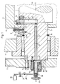
- einen Schnitt in einer Ebene der Trommelachse durch das Ende einer Bogenführungstrommel und ihrer Lagerung,
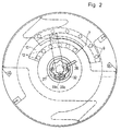
Figur 2- eine Seitenansicht der Anordnung in Figur 1,
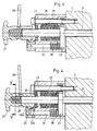
Figur 3- eine gegenüber Figur 1 im Maßstab vergrößerte Schnittdarstellung durch die Bedieneinrichtung in der Schnittebene der Figur 1 bei geschlossener Stellung der Klemmvorrichtung,
- Figur 4
- die gleiche Schnittdarstellung wie
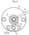
Figur 3, jedoch bei offener Stellung der Klemmvorrichtung und Figur 5- einen Schnitt nach der Linie V - V in Figur 4.
- Figure 1
- a section in a plane of the drum axis through the end of a sheet guide drum and its storage,
- Figure 2
- 2 shows a side view of the arrangement in FIG. 1,
- Figure 3
- 2 shows a sectional view, enlarged on a scale compared to FIG. 1, through the operating device in the sectional plane of FIG. 1 with the clamping device in the closed position,
- Figure 4
- the same sectional view as Figure 3, but with the clamping device and
- Figure 5
- a section along the line V - V in Figure 4.
Die Bogenführungstrommel nach dem Ausführungsbeispiel weist eine innere Welle 1 aus vollem Material und eine äußere Trommel mit wenigstens einem gegenüber der inneren Welle 1 in Umfangsrichtung verstellbaren Segment 2 auf. Anstelle einer solchen Welle kann die Bogenführungstrommel auch einen Trommelkörper mit angegossenen Zapfen zur Lagerung der Trommel aufweisen, so daß die nachfolgend beschriebene Ausbildung in einem solchen Zapfen vorgesehen ist.The sheet guide drum according to the embodiment has an inner shaft 1 made of solid material and an outer Drum with at least one
An der Mantelfläche des Segments ist eine Bogenanlagefläche ausgebildet. Es kann außerdem mit Saugdüsen oder anderen Einrichtungen zur Bogenglättung oder zur Ergreifung von Bogen versehen sein. Dieses Segment 2 ist mit der inneren Welle 1 durch eine Klemmvorrichtung fest verriegelbar. Die innere Welle 1 ist an beiden Enden mit Lagerzapfen 3, welche einstückig mit der Welle aus vollem Material ausgebildet sind, in den Seitenwänden 4 des Maschinengestells gelagert und durch ein Zahnrad 5 antreibbar, welches außerhalb des Maschinengestells mit der Stirnseite der Welle 1 durch mehrere verteilt angeordnete Schrauben 6 verbunden ist. Für eine sichere, reibschlüssige Verriegelung der Welle 1 und des in der äußeren Trommel angeordneten Segments 2 sind nach Art einer Lamellenkupplung mehrere Reibelemente 7 an einer sich radial, möglichst nahe an der Seitenwand 4, erstreckenden Fläche 8 des Segments 2 paketförmig mit einem Abstand voneinander, zum Beispiel mittels Schrauben 9, befestigt. Ein komplementär ausgebildetes Paket aus Reibelementen 10 ist an einer sich ebenfalls radial erstreckenden Fläche eines mit dem Lagerzapfen 3 oder unmittelbar mit der Welle 1 verbundenen Widerlagers 11 zum Beispiel mittels Schrauben 12 befestigt, wobei die mit Zwischenlagen gleicher Stärke geschichteten Reibelemente 7 und die gleichermaßen mit solchen Zwischenlagen geschichteten Reibelemente 10 ineinandergreifen und sich in einem gewissen Bereich überlappen. In diesem Überlappungsbereich 13 sind die an dem Segment 2 befestigten Reibelemente 7 und die an dem Widerlager 11 befestigten Reibelemente 10 zwischen dem Widerlager 11 und einem zweiten Widerlager 14 an der Welle 1 axial gegeneinander verspannbar, so daß durch die Vermehrung der Reibflächen zwischen den Reibelementen 7 und 10 schon bei relativ geringer Klemmkraft zur Verspannung hohe Reibkräfte entstehen. Das Beispiel zeigt jeweils drei Reibelemente in einem Paket, so daß sich in dem Überlappungsbereich 13 sieben Reibflächen ergeben. In Anpassung an die Form des Segmentes 2 sind auch die Reibelemente 7 und 10 segmentförmig ausgebildet, so daß sie sich in der Seitenansicht nur über einen Teil des Umfanges erstrecken, wie aus der Figur 2 ersichtlich ist. Das Widerlager 11 wird in dem Beispiel durch ein Ringsegment gebildet, welches auf dem Lagerzapfen 3 der Welle 1 mittels Schrauben 15 befestigt ist und sich axial zusätzlich gegen einen Stützring 16 oder dergleichen abstützt.An arch contact surface is formed on the lateral surface of the segment. It can also be provided with suction nozzles or other devices for smoothing sheets or for gripping sheets. This
Die Klemmvorrichtung weist einen Klemmhebel 17 auf, der in einer seitlichen Ausnehmung 18 der Welle 1 angeordnet und hierin als Wippe mit ungleich langen Hebelarmen wirksam ist. Dieser Klemmhebel 17 stützt sich in Nähe seines äußeren Endes gegen das Widerlager 14 ab und drückt mit einem Druckstein 19 im Überlappungsbereich 13 gegen die der Fläche 8 gegenüberliegenden Innenseite des radialen Teiles des Segmentes 2, so daß die Druckkräfte parallel zur Längsachse 20 der Welle 1 wirksam sind. In Richtung der Wellenachse 20 drückt gegen das andere Ende des Klemmhebels 17 die Stirnfläche einer Spannstange 21, die in Klemmrichtung permanent federbelastet ist. Diese Spannstange 21 ist zentral oder exzentrisch in einer parallel zur Wellenachse 20 angeordneten Ausnehmung 22 angeordnet und mit dem gegenüberliegenden Ende stirnseitig aus dem Lagerzapfen 3 der Welle 1 herausgeführt. Außerhalb des Lagerzapfens 3 weist die Spannstange 21 einen Ringflansch 23 auf, der an wenigstens einer Stelle von einer Schraube 24 durchgriffen wird, die die Spannstange 21 ohne Behinderung ihrer Axialverschieblichkeit gegen Verdrehung sichert. Außerhalb des Radialflansches 23 ist ein Federpaket 25, zum Beispiel aus Tellerfedern, angeordnet, welches sich einerseits gegen den Radialflansch 23 und andererseits gegen die Innenseite einer Gehäuseglocke 26 abstützt, die durch die Schraube 24 und weitere, auf der Zeichnung nicht dargestellte Schrauben mit der Stirnseite des Lagerzapfens 3 fest verbunden ist. Zu diesem Zweck weist das Zahnrad 5 eine zentrale Ausnehmung auf, die den Durchgriff der Gehäuseglocke 26 ermöglicht. Durch die Feder 25 wird die Spannstange 21 ständig gegen das innere Ende des Klemmhebels 17 gedrückt, so daß über diesen Klemmhebel 17 die Federkräfte vervielfacht und auf die Reibflächen der Reibelemente 7 und 10 übertragen werden. Damit ist die Klemmkraft zwischen den Reibelementen ausschließlich von der Federkraft der Feder 25 und nicht von Bedienkräften abhängig. Das freie Ende der Spannstange 21 ist durch den Boden der Gehäuseglocke 26 nach außen geführt und hier mit einem Betätigungsorgan 27 verbunden. Das Beispiel zeigt ein Gewinde auf dem äußeren Ende der Spannstange 21, auf welches ein Innengewinde des Betätigungsorgans aufschraubbar ist, welches mit einer Vorrichtung zur elektrischen Absicherung der Klemmvorrichtung zusammenwirkt. Zu diesem Zweck erfolgt die Verschraubung des Betätigungsorgans 27 auf dem Gewinde der Spannstange 21, ausgehend von der Klemmstellung, zunächst auf einem Leerweg, der zur Betätigung der elektrischen Absicherung bestimmt ist. Beispielsweise dargestellt ist ein Schaltorgan 28, welches als Kipphebel maschinenfest gelagert ist und mit dem einen Ende in eine Umfangsausnehmung 29 am Betätigungsorgan eingreift, während das andere Ende gegen einen elektrischen Schalter 30 wirkt, wobei eine Feder 31 das Schaltorgan 28 in Richtung der Ausgangslage vor seiner Bewegung belastet. Erst nach dem Leerweg kommt das Betätigungsorgan 27 gegen ein Axialwälzlager 36 an der Außenseite der Gehäuseglocke 26 zur Anlage, so daß bei weiterer Verschraubung die Spannstange 21 in der Zeichenebene nach links axial verschoben wird. Dadurch wird der Klemmhebel 17 entlastet, so daß die reibschlüssige Verbindung zwischen den Reibelementen 7 und 10 aufgehoben wird. Bei Verdrehung des Betätigungsorgans 27 in Gegenrichtung drückt die Feder 25 zunächst die Spannstange 21 mit der Kraft der Feder 25 gegen das innere Ende des Klemmhebels 17, so daß die reibschlüssige Verbindung zwischen den Reibelementen 9 und 10 wieder hergestellt wird, bevor das Betätigungsorgan 27 auf dem Leerweg in die Ausgangslage zurückgedreht werden kann, wobei es über das Schaltorgan 28 den Schalter 30 zur elektrischen Absicherung der Klemmvorrichtung wieder freigibt.The clamping device has a clamping
Nach einem an sich selbständigen Erfindungsgedanken sind die Endlagen für die Bewegung des Betätigungsorgans 27 durch Anschläge 32 bzw. 33a und 33b begrenzt, die so ausgelegt sind, daß sie zugleich den Leerweg für die Schaltung der elektrischen Absicherung definieren. Dazu ist vorgesehen, daß die Spannstange 21 den die Drehung beim Lösen der Klemmvorrichtung begrenzenden Anschlag 33b am Ende ihrer axialen Bewegung in seine Wirkungsposition verschiebt. Außerdem ist die axiale Überdeckung des radial wirksamen Anschlages 32 mit den Anschlägen 33a bzw. 33b in den Anschlaglagen kleiner als die Steigung des Gewindes auf dem freien Ende der Spannstange 21 bzw. in dem Betätigungsorgan 27. Vorgesehen sind ein Anschlag 32 aus einer Nocke an dem Betätigungsorgan 27, wobei diese Nocke zwei Anschlagflächen aufweist, von denen je eine pro Drehrichtung wirksam ist, und Gegenanschläge 33a und 33b an drehfesten Maschinenteilen, die in Achsrichtung der Spannstange bzw der Welle einen auf den Leerweg abgestimmten Abstand voneinander aufweisen und axial verschiebbar am außenliegenden Ende eines in der Gehäuseglocke 26 axial beweglichen Bolzens 34 angeordnet sind, dessen inneres Ende sich gegen den Radialflansch 23 der Spannstange 21 abstützt. Durch die gegenüber der Gewindesteigung kleinere Überdeckung des Anschlages 32 mit den Anschlägen 33a bzw. 33b und durch den axialen Abstand der beiden letzteren Anschläge 33a und 33b voneinander wird erreicht, daß der Anschlag 32 am Betätigungsorgan 27 mehrere Umdrehungen des Betätigungsorganes 27 zur Erzielung eines ausreichend langen Leerweges für die Betätigung der elektrischen Absicherung ausführen kann und auch noch verdrehbar ist, um eine axiale Verschiebung der Spannstange 21 gegen die Wirkung der Feder 25 zum Lösen der Klemmvorrichtung zu ermöglichen, bevor der Anschlag 32 in der Endlage bei gelöster Klemmvorrichtung gegen den Anschlag 33b zur Anlage kommt. Zu diesem Zweck wird der Anschlag 33b durch den Bolzen 34, ausgehend von der Axialbewegung der Spannstange 21, geringfügig axial verschoben, so daß er in den Drehkreis des Anschlages 32 eingreift. Bei der ersten Umdrehung des Betätigungsorgans 27 in Gegenrichtung verschiebt sich die Spannstange 21 nach rechts, so daß auch der Anschlag 33b, unterstützt durch die Feder 35, nach rechts gegen die Gehäuseglocke 26 zur Anlage kommt und dem Anschlag 32 bei der nächsten Umdrehung des Betätigungsorganes 27 nicht mehr im Wege ist. Erst nach dem Zurücklegen des Leerweges kommt der Anschlag 32 gegen den Anschlag 33a wieder zur Anlage, so daß dadurch die andere Endlage des Betätigungsorgans begrenzt ist. Die Figur 4 zeigt die Anschlagberührung bei gelöster Klemmvorrichtung.According to a concept of the invention that is independent per se, the end positions for the movement of the actuating
Anstelle des beschriebenen, von Hand verdrehbaren Betätigungsorganes 27 kann auch ein motorisch bewegtes Betätigungsorgan für die Spannstange 21 vorgesehen sein.Instead of the described, manually rotatable actuating
- 11
- Wellewave
- 22nd
- Segmentsegment
- 33rd
- LagerzapfenBearing journal
- 44th
- SeitenwandSide wall
- 55
- Zahnradgear
- 66
- Schraubescrew
- 77
- ReibelementFriction element
- 88th
- Flächearea
- 99
- Schraubescrew
- 1010th
- ReibelementFriction element
- 1111
- WiderlagerAbutment
- 1212
- Schraubescrew
- 1313
- ÜberlappungsbereichOverlap area
- 1414
- WiderlagerAbutment
- 1515
- Schraubescrew
- 1616
- StützringSupport ring
- 1717th
- KlemmhebelClamping lever
- 1818th
- AusnehmungRecess
- 1919th
- DrucksteinPressure stone
- 2020th
- MittelachseCentral axis
- 2121
- SpannstangeTension rod
- 2222
- AusnehmungRecess
- 2323
- RadialflanschRadial flange
- 2424th
- Schraubescrew
- 2525th
- Federfeather
- 2626
- GehäuseglockeBell housing
- 2727
- BetätigungsorganActuator
- 2828
- SchaltorganSwitching element
- 2929
- UmfangsnutCircumferential groove
- 3030th
- Schaltercounter
- 3131
- Federfeather
- 3232
- Anschlagattack
- 33a33a
- Anschlagattack
- 33b33b
- Anschlagattack
- 3434
- Bolzenbolt
- 3535
- Federfeather
- 3636
- AxialwälzlagerAxial roller bearings
Claims (13)
- Sheet-guiding drum for a printing machine for either single-sided printing or printing and perfecting, comprising at least two sheet-guiding surfaces (8) provided at the circumference of segments defining an outer drum part, said sheet-guiding surfaces being adjustable in circumferential direction with respect to an axial support member (1, 3) and lockable with said axial support member by means of a clamping device (7, 10, 17, 25), said clamping device featuring radially directed friction surfaces being disposed on said segment (2) of said outer drum part and on said axial support member and being pressable one against the other in axial direction by means of a tension rod (21) movable in axial direction of said axial support member,
characterized in that
said friction surfaces being formed on said lamellarly interengaging friction elements (7, 10) alternately connected to a segment of said drum and said axial support member so as to be fixed against rotation relative thereto and being clampable, by means of a movable clamping lever (17) disposed transversely to the axial direction of the clamping force, between two counter-bearings (11, 14) supported on said axial support member, said clamping lever (17) acting as a rocker and having one end thereof spring-loaded in clamping direction of said clamping force (25) by means of said tension rod (21) secured against rotation. - Sheet-guiding drum according to Claim 1,
characterized in
that the clamping lever (17) is disposed in a lateral recess (18) formed in the shaft (1) and that the tension rod (21) is provided in a bore (22) extending, in direction of a shaft axis (20), from an end face to said lateral recess (18). - Sheet-guiding drum according to Claim 2,
characterized in
that, in an overlapping region (13) of the friction elements (7, 10), the outwardly extending end of the clamping lever (17), loosely disposed in the lateral recess (18), is active against the inner side of a flange formed on the segment (2) so as to extend radially inwardly and is supported against a counter-bearing (14) disposed in a defining wall of said lateral recess (18) of the shaft (1) on a side thereof located opposite the friction surfaces of said friction elements (7, 10), said counter-bearing being located at a shorter radial distance from said outwardly directed end of said clamping lever than the other end thereof. - Sheet-guiding drum according to Claim 3,
characterized in
that supporting surfaces for the clamping lever (17) are formed of inserts of hardened material. - Sheet-guiding drum according to Claim 5,
characterized in
that to an end face (8) of the segment (2) radially extending towards the shaft axis (20) there is, on one hand, secured a plurality of friction elements (7) and relatively thin intermediate layers and to a surface of the shaft (1) extending radially towards said shaft axis (20) there is, on the other hand, secured a plurality of friction elements (10) complementary thereto, the overlapping region (13) of said interengaging friction elements (7, 10) being disposed in a force flux of said two counter-bearings for the clamping force. - Sheet-guiding drum according to Claim 1,
characterized in
that, by means an actuating means (28) disposed at an end face of the shaft (1), the tension rod (21) can be retracted against the action of the spring (25) biasing said tension rod in clamping direction, said actuating means being equipped with an electrical protection device (30) and being coupable with said tension rod so as to displace said tension rod in axial direction only after transversing an axially effective idle path for the purpose of switching said protection device. - Sheet-guiding drum according to Claim 6,
characterized in
that the spring (25) biasing the tension rod (21) in clamping direction is supported in a bell-shaped housing (26), secured to the end face of the shaft (1), against said housing, on one hand, and against said tension rod (21), on the other hand, a free end of said tension rod being axially displaceable outwardly through said housing and featuring a thread on which a corresponding internal thread of the actuating means (27) is screwable for axially displacing said tension rod (21) over a first distance corresponding to said idle path, and over a second succeeding distance wherein said actuating member is braced against said bell-shaped housing (26). - Sheet-guiding drum according to Claim 7,
characterized in
that end positions for the displacement of the actuating means (27) are limited by stops (32, 33a, 33b), at the same time said stops define the idle path for switching an electrical protection device (30), the tension rod (21) displacing a stop limiting turning of said actuating means (27) at the end of the axial displacement thereof, when said clamping device is released, into an operative position thereof. - Sheet-guiding drum according to Claim 8,
characterized in
that in the stop positions the axial overlapping of the radially effective stops (32 and 33a, 33b) is smaller than the pitch of the thread with which the actuating means (27) is screwable onto the tension rod (21). - Sheet-guiding drum according to Claims 8 and 9,
characterized in
that the stops (32 and 33a, 33b) consist of a cam formed on the actuating means (27) and of two cams fixed against rotation, said two cams being spaced from one another in the displacement direction of the tension rod a distance corresponding to the length of said idle path and being disposed so as to be axially displaceable. - Sheet-guiding drum according to Claim 10,
characterized in
that the two axially displaceable cams formig the stops (33a, 33b) are secured to the outer end of a bolt (34), guided in the bell-shaped housing (26), the inner end of said bolt being axially supported against the tension rod (21) under biasing action of a spring (35). - Sheet-guiding drum according to Claim 11,
characterized in
that the bell-shaped housing (26) with the tension rod (21), spring-biased in clamping direction and disposed in said housing, as well as the actuating means (27), the stop limitation of said actuating means, and with switching elements (28) of the electrical protection device (30) are designed as pre-fabricatable structural units and may be secured to the end face of the shaft (1) by means of screws (24). - Sheet-guiding drum according to one or several of the preceding claims 1 through 12,
characterized in
that the actuating means (27) is a nut manually screwable on the thread of the tension rod (21).
Applications Claiming Priority (2)
| Application Number | Priority Date | Filing Date | Title |
|---|---|---|---|
| DE3900818 | 1989-01-13 | ||
| DE3900818A DE3900818C1 (en) | 1989-01-13 | 1989-01-13 |
Publications (3)
| Publication Number | Publication Date |
|---|---|
| EP0377860A2 EP0377860A2 (en) | 1990-07-18 |
| EP0377860A3 EP0377860A3 (en) | 1991-04-03 |
| EP0377860B1 true EP0377860B1 (en) | 1993-09-01 |
Family
ID=6371996
Family Applications (1)
| Application Number | Title | Priority Date | Filing Date |
|---|---|---|---|
| EP89123293A Expired - Lifetime EP0377860B1 (en) | 1989-01-13 | 1989-12-15 | Sheet transfer drum for printing machines for first impression printing or for perfecting |
Country Status (9)
| Country | Link |
|---|---|
| US (1) | US5105737A (en) |
| EP (1) | EP0377860B1 (en) |
| JP (1) | JPH082639B2 (en) |
| CN (1) | CN1012566B (en) |
| AU (1) | AU630651B2 (en) |
| CA (1) | CA2007787C (en) |
| DE (2) | DE3900818C1 (en) |
| ES (1) | ES2045370T3 (en) |
| HK (1) | HK10494A (en) |
Families Citing this family (14)
| Publication number | Priority date | Publication date | Assignee | Title |
|---|---|---|---|---|
| DE4131273C1 (en) * | 1991-09-20 | 1992-12-10 | Heidelberger Druckmaschinen Ag, 6900 Heidelberg, De | |
| DE4141817C2 (en) * | 1991-12-18 | 1993-10-07 | Roland Man Druckmasch | Gear train separation device |
| JP3160121B2 (en) * | 1992-07-15 | 2001-04-23 | ハイデルベルガー ドルツクマシーネン アクチエンゲゼルシヤフト | Method and apparatus for performing and stopping sheet reversal and for format adjustment when transporting sheets through a printing press |
| DE4223190C2 (en) * | 1992-07-15 | 1995-12-07 | Heidelberger Druckmasch Ag | Device for turning the sheet turning on and off when conveying sheets through a printing machine |
| DE4322477C2 (en) * | 1992-07-15 | 1995-12-21 | Heidelberger Druckmasch Ag | Method and device for starting and stopping the sheet turning and for setting the format when conveying sheets through a printing press |
| JP3074105B2 (en) * | 1993-05-13 | 2000-08-07 | 株式会社桜井グラフィックシステムズ | Sheet reversing mechanism of sheet-fed printing press |
| DE4401684C2 (en) * | 1994-01-21 | 1998-04-09 | Heidelberger Druckmasch Ag | Adjustment device for a printing press |
| US5631731A (en) * | 1994-03-09 | 1997-05-20 | Nikon Precision, Inc. | Method and apparatus for aerial image analyzer |
| DE4410385C2 (en) * | 1994-03-25 | 1997-07-17 | Roland Man Druckmasch | Device for fastening printing plates |
| JP3524471B2 (en) * | 2000-05-16 | 2004-05-10 | リョービ株式会社 | Sheet-fed printing press that can switch between double-sided printing and single-sided printing |
| DE10122227B4 (en) * | 2001-05-08 | 2012-03-01 | Koenig & Bauer Aktiengesellschaft | Storage drum in turning devices of sheet-fed printing machines |
| DE10260767A1 (en) | 2002-12-23 | 2004-07-01 | Koenig & Bauer Ag | Device for format adjustment on sheet-guiding drums of sheet-fed printing machines |
| DE10260758B3 (en) * | 2002-12-23 | 2004-04-29 | Koenig & Bauer Ag | Device for sheet print machine guide drum format adjustment has axially movable actuating element transferring linear actuation motion as drive element of gearbox producing carrier body rotary motion |
| JP4414180B2 (en) * | 2003-09-18 | 2010-02-10 | 株式会社小森コーポレーション | Torso device |
Family Cites Families (14)
| Publication number | Priority date | Publication date | Assignee | Title |
|---|---|---|---|---|
| GB817354A (en) * | 1955-11-11 | 1959-07-29 | Reyrolle A & Co Ltd | Improvements relating to printing press drives |
| DE2708478C3 (en) * | 1977-02-26 | 1981-11-12 | Koenig & Bauer AG, 8700 Würzburg | Transfer and turning drum for a sheet-fed rotary printing press |
| DE2824733C2 (en) * | 1978-06-06 | 1984-03-15 | Heidelberger Druckmaschinen Ag, 6900 Heidelberg | Transfer drum for perfecting presses |
| JPS5871162A (en) * | 1981-10-24 | 1983-04-27 | Komori Printing Mach Co Ltd | Phase adjusting device of rotary sheet-fed press with reversing mechanism |
| JPS58170278A (en) * | 1982-03-31 | 1983-10-06 | Fujitsu Ltd | Character size controlling system |
| US4513633A (en) * | 1982-04-08 | 1985-04-30 | Eaton Corporation | Positive drive and generated cam surfaces therefor |
| DE8319431U1 (en) * | 1983-07-06 | 1984-02-16 | Heidelberger Druckmaschinen Ag, 6900 Heidelberg | DEVICE FOR CONVERTING TO SELECTIVE SHEET PRINTING OR BEAUTIFUL AND REPRINTING A TURNING DEVICE ARRANGED BETWEEN THE INDIVIDUAL PRINTING WORKS OF AN ARC ROTATION PRINTING MACHINE |
| US4621242A (en) * | 1984-03-19 | 1986-11-04 | The Perkin-Elmer Corporation | R.F. impedance match control system |
| DE3410689A1 (en) * | 1984-03-23 | 1985-10-03 | M.A.N.- Roland Druckmaschinen AG, 6050 Offenbach | DEVICE ON THE STORAGE DRUM OF A SHEET PRINTING MACHINE FOR SELECTIVE PRINTING AND REPRINTING |
| DE3534488A1 (en) * | 1985-09-27 | 1987-04-16 | Koenig & Bauer Ag | CLUTCH IN AN ARC ROTATION PRINTING MACHINE |
| DE3534486A1 (en) * | 1985-09-27 | 1987-04-16 | Koenig & Bauer Ag | CLUTCH IN AN ARC ROTATION PRINTING MACHINE |
| DE3611325A1 (en) * | 1986-04-04 | 1987-10-08 | Heidelberger Druckmasch Ag | DEVICE FOR ADJUSTING THE RELATIVE ROTATION BETWEEN A GEAR WHEEL AND A GEAR WHEEL BEARING WITH THIS SIMULTANEOUSLY |
| JPH0667615B2 (en) * | 1986-04-21 | 1994-08-31 | 株式会社小森コーポレーション | Adsorption member fixing device for sheet-fed printing press with reversing mechanism |
| US4831929A (en) * | 1987-10-21 | 1989-05-23 | Komori Printing Machinery Co., Ltd. | Suction member fixing apparatus for sheet-fed printing press with turn-over mechanism |
-
1989
- 1989-01-13 DE DE3900818A patent/DE3900818C1/de not_active Expired - Lifetime
- 1989-12-15 ES ES89123293T patent/ES2045370T3/en not_active Expired - Lifetime
- 1989-12-15 DE DE89123293T patent/DE58905470D1/en not_active Expired - Fee Related
- 1989-12-15 EP EP89123293A patent/EP0377860B1/en not_active Expired - Lifetime
-
1990
- 1990-01-09 CN CN90100033A patent/CN1012566B/en not_active Expired
- 1990-01-11 AU AU47881/90A patent/AU630651B2/en not_active Ceased
- 1990-01-15 CA CA002007787A patent/CA2007787C/en not_active Expired - Fee Related
- 1990-01-16 JP JP2004662A patent/JPH082639B2/en not_active Expired - Lifetime
- 1990-01-16 US US07/465,906 patent/US5105737A/en not_active Expired - Lifetime
-
1994
- 1994-02-02 HK HK104/94A patent/HK10494A/en not_active IP Right Cessation
Also Published As
| Publication number | Publication date |
|---|---|
| HK10494A (en) | 1994-02-09 |
| CN1012566B (en) | 1991-05-08 |
| CN1044257A (en) | 1990-08-01 |
| CA2007787C (en) | 1994-07-05 |
| US5105737A (en) | 1992-04-21 |
| CA2007787A1 (en) | 1990-07-13 |
| AU630651B2 (en) | 1992-11-05 |
| JPH03252A (en) | 1991-01-07 |
| AU4788190A (en) | 1990-07-19 |
| DE3900818C1 (en) | 1990-05-10 |
| EP0377860A2 (en) | 1990-07-18 |
| JPH082639B2 (en) | 1996-01-17 |
| EP0377860A3 (en) | 1991-04-03 |
| DE58905470D1 (en) | 1993-10-07 |
| ES2045370T3 (en) | 1994-01-16 |
Similar Documents
| Publication | Publication Date | Title |
|---|---|---|
| EP0598791B1 (en) | Device for clamping and adjusting flexible printing plates on plate cylinders of rotary printing presses | |
| EP0377860B1 (en) | Sheet transfer drum for printing machines for first impression printing or for perfecting | |
| EP0340452B1 (en) | Device for adjusting the angular position of a cylinder in a sheet overturning device, and device for axially shifting an adjusting member for the gripper conversion device of the cylinder in a rotary printing machine | |
| DE19831694A1 (en) | Printing unit for a web-fed rotary printing press | |
| EP0346619B1 (en) | Device for fixing the relative position between a toothed gear and a coaxially toothed ring in a rotary sheet printing machine | |
| EP0392207B1 (en) | Register adjusting device for sheet transfer drums of a printing machine | |
| EP0442265B1 (en) | Clamping device for an axial movable actuator for the reversal of the gripper with a sheet-fed rotary letterpress | |
| DE4131273C1 (en) | ||
| DE4221046A1 (en) | Transfer drum for printing machines | |
| DE4444062A1 (en) | Adjustable alignment device for printing plates | |
| EP0172412B1 (en) | Sheet transfer cylinder in sheet-fed rotary presses | |
| EP0755785B1 (en) | Device for attaching printing plates with means for reducing pressure-free zone | |
| DE4242606C2 (en) | Device for adjusting sheet hold-downs | |
| EP0377857B1 (en) | Electrical security device for a clamping device in a sheet transfer drum of a printing press | |
| EP0553739B1 (en) | Sheet guide element adjusting device in rotary printing machines | |
| WO2001083215A1 (en) | Device for providing a cylinder with a packing and registers | |
| EP0508113B1 (en) | Device for the rapid precise clamping and tensioning of printing plates on the forme cylinder of a printing press | |
| EP0155987A2 (en) | Rotation and adjustment tool for axially symmetric elements, particularly steering tie-rods of motor vehicles | |
| EP0425935A2 (en) | Device for the parallel tensioning of printing plates | |
| DE2720673B2 (en) | Device for uneven tensioning of a rubber blanket in an offset printing machine | |
| DE2910114C2 (en) | Clamping head for the core tubes of wraps made of paper, plastic films and the like. | |
| DE19509562C1 (en) | Device for releasing plates from a cylinder | |
| DE1178442B (en) | Device for clamping flexible printing plates on forme cylinders of printing machines | |
| DE102004045098B4 (en) | Device for the remote-controlled actuation of clamping elements | |
| DE1807545A1 (en) | Clamping device for flexible printing plates on a cylinder of a rotary printing machine |
Legal Events
| Date | Code | Title | Description |
|---|---|---|---|
| PUAI | Public reference made under article 153(3) epc to a published international application that has entered the european phase |
Free format text: ORIGINAL CODE: 0009012 |
|
| 17P | Request for examination filed |
Effective date: 19891215 |
|
| AK | Designated contracting states |
Kind code of ref document: A2 Designated state(s): CH DE ES FR GB IT LI NL SE |
|
| PUAL | Search report despatched |
Free format text: ORIGINAL CODE: 0009013 |
|
| AK | Designated contracting states |
Kind code of ref document: A3 Designated state(s): CH DE ES FR GB IT LI NL SE |
|
| 17Q | First examination report despatched |
Effective date: 19930218 |
|
| GRAA | (expected) grant |
Free format text: ORIGINAL CODE: 0009210 |
|
| AK | Designated contracting states |
Kind code of ref document: B1 Designated state(s): CH DE ES FR GB IT LI NL SE |
|
| REF | Corresponds to: |
Ref document number: 58905470 Country of ref document: DE Date of ref document: 19931007 |
|
| ET | Fr: translation filed | ||
| ITF | It: translation for a ep patent filed |
Owner name: STUDIO JAUMANN |
|
| GBT | Gb: translation of ep patent filed (gb section 77(6)(a)/1977) |
Effective date: 19931029 |
|
| REG | Reference to a national code |
Ref country code: ES Ref legal event code: FG2A Ref document number: 2045370 Country of ref document: ES Kind code of ref document: T3 |
|
| PLBE | No opposition filed within time limit |
Free format text: ORIGINAL CODE: 0009261 |
|
| STAA | Information on the status of an ep patent application or granted ep patent |
Free format text: STATUS: NO OPPOSITION FILED WITHIN TIME LIMIT |
|
| 26N | No opposition filed | ||
| EAL | Se: european patent in force in sweden |
Ref document number: 89123293.6 |
|
| PGFP | Annual fee paid to national office [announced via postgrant information from national office to epo] |
Ref country code: ES Payment date: 19961220 Year of fee payment: 8 Ref country code: SE Payment date: 19961220 Year of fee payment: 8 |
|
| PG25 | Lapsed in a contracting state [announced via postgrant information from national office to epo] |
Ref country code: SE Free format text: LAPSE BECAUSE OF NON-PAYMENT OF DUE FEES Effective date: 19971216 Ref country code: ES Free format text: LAPSE BECAUSE OF NON-PAYMENT OF DUE FEES Effective date: 19971216 |
|
| EUG | Se: european patent has lapsed |
Ref document number: 89123293.6 |
|
| PGFP | Annual fee paid to national office [announced via postgrant information from national office to epo] |
Ref country code: NL Payment date: 19981222 Year of fee payment: 10 |
|
| PGFP | Annual fee paid to national office [announced via postgrant information from national office to epo] |
Ref country code: CH Payment date: 19990108 Year of fee payment: 10 |
|
| PG25 | Lapsed in a contracting state [announced via postgrant information from national office to epo] |
Ref country code: LI Free format text: LAPSE BECAUSE OF NON-PAYMENT OF DUE FEES Effective date: 19991231 Ref country code: CH Free format text: LAPSE BECAUSE OF NON-PAYMENT OF DUE FEES Effective date: 19991231 |
|
| PG25 | Lapsed in a contracting state [announced via postgrant information from national office to epo] |
Ref country code: NL Free format text: LAPSE BECAUSE OF NON-PAYMENT OF DUE FEES Effective date: 20000701 |
|
| NLV4 | Nl: lapsed or anulled due to non-payment of the annual fee |
Effective date: 20000701 |
|
| REG | Reference to a national code |
Ref country code: ES Ref legal event code: FD2A Effective date: 20010503 |
|
| REG | Reference to a national code |
Ref country code: GB Ref legal event code: IF02 |
|
| PGFP | Annual fee paid to national office [announced via postgrant information from national office to epo] |
Ref country code: GB Payment date: 20051122 Year of fee payment: 17 |
|
| PG25 | Lapsed in a contracting state [announced via postgrant information from national office to epo] |
Ref country code: IT Free format text: LAPSE BECAUSE OF NON-PAYMENT OF DUE FEES;WARNING: LAPSES OF ITALIAN PATENTS WITH EFFECTIVE DATE BEFORE 2007 MAY HAVE OCCURRED AT ANY TIME BEFORE 2007. THE CORRECT EFFECTIVE DATE MAY BE DIFFERENT FROM THE ONE RECORDED. Effective date: 20051215 |
|
| PGFP | Annual fee paid to national office [announced via postgrant information from national office to epo] |
Ref country code: FR Payment date: 20051216 Year of fee payment: 17 |
|
| GBPC | Gb: european patent ceased through non-payment of renewal fee |
Effective date: 20061215 |
|
| REG | Reference to a national code |
Ref country code: FR Ref legal event code: ST Effective date: 20070831 |
|
| PG25 | Lapsed in a contracting state [announced via postgrant information from national office to epo] |
Ref country code: GB Free format text: LAPSE BECAUSE OF NON-PAYMENT OF DUE FEES Effective date: 20061215 |
|
| PG25 | Lapsed in a contracting state [announced via postgrant information from national office to epo] |
Ref country code: FR Free format text: LAPSE BECAUSE OF NON-PAYMENT OF DUE FEES Effective date: 20070102 |
|
| PGFP | Annual fee paid to national office [announced via postgrant information from national office to epo] |
Ref country code: DE Payment date: 20071210 Year of fee payment: 19 |
|
| PG25 | Lapsed in a contracting state [announced via postgrant information from national office to epo] |
Ref country code: DE Free format text: LAPSE BECAUSE OF NON-PAYMENT OF DUE FEES Effective date: 20090701 |