EP0532142B1 - Procédé et dispositif de contrÔle des pièces ferromagnétiques par ultrasons - Google Patents
Procédé et dispositif de contrÔle des pièces ferromagnétiques par ultrasons Download PDFInfo
- Publication number
- EP0532142B1 EP0532142B1 EP92250255A EP92250255A EP0532142B1 EP 0532142 B1 EP0532142 B1 EP 0532142B1 EP 92250255 A EP92250255 A EP 92250255A EP 92250255 A EP92250255 A EP 92250255A EP 0532142 B1 EP0532142 B1 EP 0532142B1
- Authority
- EP
- European Patent Office
- Prior art keywords
- accordance
- transmission
- piece
- alternating
- coupling piece
- Prior art date
- Legal status (The legal status is an assumption and is not a legal conclusion. Google has not performed a legal analysis and makes no representation as to the accuracy of the status listed.)
- Expired - Lifetime
Links
Images


Classifications
-
- G—PHYSICS
- G01—MEASURING; TESTING
- G01N—INVESTIGATING OR ANALYSING MATERIALS BY DETERMINING THEIR CHEMICAL OR PHYSICAL PROPERTIES
- G01N29/00—Investigating or analysing materials by the use of ultrasonic, sonic or infrasonic waves; Visualisation of the interior of objects by transmitting ultrasonic or sonic waves through the object
- G01N29/22—Details, e.g. general constructional or apparatus details
- G01N29/24—Probes
- G01N29/2412—Probes using the magnetostrictive properties of the material to be examined, e.g. electromagnetic acoustic transducers [EMAT]
-
- G—PHYSICS
- G01—MEASURING; TESTING
- G01N—INVESTIGATING OR ANALYSING MATERIALS BY DETERMINING THEIR CHEMICAL OR PHYSICAL PROPERTIES
- G01N29/00—Investigating or analysing materials by the use of ultrasonic, sonic or infrasonic waves; Visualisation of the interior of objects by transmitting ultrasonic or sonic waves through the object
- G01N29/04—Analysing solids
- G01N29/06—Visualisation of the interior, e.g. acoustic microscopy
- G01N29/0609—Display arrangements, e.g. colour displays
- G01N29/0645—Display representation or displayed parameters, e.g. A-, B- or C-Scan
Definitions
- the invention relates to a method for testing ferromagnetic workpieces by means of ultrasonic waves according to the preamble of the main claim.
- the receiving system In the case of the electrodynamic ultrasound test with coupled transceiver systems, the receiving system is overloaded due to inductive couplings during and immediately after transmission. Ultrasound signals cannot be received for a period of time after transmission. Since you also want to detect defects in the workpiece close to the test head and measure small wall thicknesses, you endeavor to keep the so-called dead zone as small as possible.
- the object of the invention is to provide an improved method for testing ferromagnetic workpieces by means of ultrasound waves with a coupled transmitting and receiving coil system, with which errors close to the probe in the case of angular irradiation in the range of ⁇ 10 mm and wall thicknesses ⁇ 2 mm can be measured.
- a shortening of the dead zone in the case of coupled transmitting / receiving coil systems can, beyond the suppression of unwanted ultrasonic excitation in the test head itself (area 3), only take place over the second area of the dead zone, the recovery phase of the receiving system.
- the dead zone is e.g. reduced to values of less than 7 microseconds in the case of angular irradiation.
- the temporal amplitude profile of the signal coupled into the receiving circuit must first be adapted to the profile of the recovery phase of the receiving system (area 2). Once the amplitude curve has been determined, it must be fed into the receiving system in a time-synchronized manner with each transmission pulse.
- the signal source required for the electrical coupling must be protected from high voltages induced in the receiving system during the first region of the dead zone by means of suitable, known electronic circuits.
- the proposed measure for damping the overdrive when decaying is particularly effective when part of the alternating magnetic field, which is required for coupling-free, magnetostrictive ultrasound excitation, is inductively coupled into the coil system.
- a value of 0.5 mm is preferably proposed for the distance between the coupling piece / meander back and a value against 0 mm for the distance between the coupling piece and the pole shoe.
- the test device is particularly advantageous when the magnetic yoke is designed as a ring yoke.
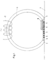
- FIG. 1 shows a schematic representation of the US test device according to the invention.
- the test device To generate the horizontal alternating magnetic field, the test device has a ring yoke 1 and an alternating field coil 2 as magnets. Between the pole pieces 3, 4 of the magnet 1, the coil system, here designed as a transmitting and receiving meander 5, is arranged.
- the coil system 5 is held by a non-magnetic transducer carrier 6, for. B. plastic.
- the workpiece 7 to be tested moves just below the coil system 5 relative to the test device.
- a ferromagnetic coupling piece 8 is arranged on the side of the coil system 5 facing away from the test object. This covers part of the coil system 5, here in this illustration, for example, about 50% of the width.
- the distance between coupling piece 8 / coil system 5 and also the distance between coupling piece 8 / pole shoe 4 can be changed.
- the variation range for the first-mentioned distance is in the range of 0-1 mm and for the second-mentioned distance in the range of 0-10 mm.
- FIGS. 2-5 show the A-scan with a horizontal magnetic field without the coupling according to the invention.
- the first area of the pulse train is the area 10 of the forced oscillation.
- the subsequent area is area 11 of the recovery phase of the receiving system.
- the sum of both is the dead zone area 12, which cannot be used for signal evaluation.
- an artificial error 13 was sounded, which was arranged far enough away that it could also be identified with the very wide dead zone 12.
- FIG. 3 The improvement according to the invention is shown in FIG. 3, in which the area of the recovery phase 11 was almost compensated for by an optimal inductive coupling and the remaining dead zone 12.1 practically coincides with the area of the forced oscillation 10.
- the magnetic current profile 14, 14.1 has also been plotted in addition to the test image.
- the magnetic current curve 14 is optimal in terms of compensation and the runtime spread Fig. 4b clearly shows the greatly shortened dead zone 12.1 and the clearly identifiable error echo 13.1.
- the edge echo 15 is also shown in this illustration.
- the situation is shown in Fig. 5a, which results when the magnetic current profile 14.1 is inverted. This is equivalent to a change in the magnetic polarity of the ring magnet 1.
- the dead zone 12.3 increases again considerably and the test sensitivity is deteriorated so much that the false echo 13.1 can no longer be recognized.
- the edge echo 15 can still be clearly identified.
Landscapes
- Physics & Mathematics (AREA)
- Biochemistry (AREA)
- Health & Medical Sciences (AREA)
- Life Sciences & Earth Sciences (AREA)
- Chemical & Material Sciences (AREA)
- Analytical Chemistry (AREA)
- General Health & Medical Sciences (AREA)
- General Physics & Mathematics (AREA)
- Immunology (AREA)
- Pathology (AREA)
- Acoustics & Sound (AREA)
- Electromagnetism (AREA)
- Investigating Or Analyzing Materials By The Use Of Ultrasonic Waves (AREA)
Claims (8)
- Procédé pour contrôler des pièces ferromagnétiques au moyen d'ondes ultrasonores, un champ de magnétisation alternant et orienté parallèlement à la surface de la pièce étant engendré par l'intermédiaire d'un système magnétique disposé contre la surface de la pièce et excité par du courant alternatif, et des impulsions d'émission à hautes fréquences étant déclenchées par un système d'émission et de réception à bobines, couplé et agencé à proximité de la surface de la pièce, impulsions d'émission à hautes fréquences qui entraînent après l'émission, en raison de couplages inductifs, une surcommande du système de réception,
caractérisé en ce que, dans la zone de la phase de régénération du système de réception, par un couplage électrique ou inductif approprié dans le système de réception, on amortit la perte. - Procédé selon la revendication 1,
caractérisé en ce qu'une partie du champ magnétique alternatif est couplé inductivement dans le système à bobines, l'induction provoquée dans le système de réception par le champ alternatif étant de sens opposé à la dernière surcommande provoquée par le courant d'émission. - Dispositif pour la mise en oeuvre du procédé selon la revendication 1, comportant une culasse d'aimant (1) et un système d'émission et de réception à bobines, couplé, agencé entre les pièces polaires (3, 4) de la culasse d'aimant, et comportant des méandres d'émission et de réception (5) intercalés,
caractérisé en ce que les deux pièces polaires (3, 4) de la culasse d'aimant (1) reposent de façon jointive contre les méandres d'émission et de réception (5), et une pièce de couplage ferromagnétique (8) reliée de façon magnétiquement conductrice à une pièce polaire (4) de l'aimant à champ alternatif est agencée sur la face opposée au contrôle des méandres (5). - Dispositif selon la revendication 3,
caractérisé en ce que la pièce de couplage ferromagnétique (8) recouvre un tiers, jusqu'à deux tiers, de l'écartement des pièces polaires (3, 4) ou de la face arrière des méandres (5). - Dispositif selon l'une des revendications 3 ou 4,
caractérisé en ce que l'écartement entre la pièce de couplage ferromagnétique (8) et la face arrière des méandres (5) est situé dans le domaine de 0 à 1 mm. - Dispositif selon l'une des revendications 3 ou 4,
caractérisé en ce que l'écartement entre la pièce de couplage ferromagnétique (8) et la pièce polaire (4) est situé dans le domaine de 0 à 10 mm. - Dispositif selon l'une des revendications 3 à 6,
caractérisé en ce que la pièce de couplage ferromagnétique (8) est réalisée à partir d'un matériau composite pulvérulent connu, magnétique doux, et présentant une conductibilité électrique réduite. - Dispositif selon l'une des revendications 3 à 7,
caractérisé en ce que la culasse d'aimant est réalisée sous forme d'une culasse annulaire (1).
Applications Claiming Priority (2)
| Application Number | Priority Date | Filing Date | Title |
|---|---|---|---|
| DE4130935A DE4130935A1 (de) | 1991-09-13 | 1991-09-13 | Verfahren und vorrichtung zum pruefen ferromagnetischer werkstuecke mittels ultraschallwellen |
| DE4130935 | 1991-09-13 |
Publications (2)
| Publication Number | Publication Date |
|---|---|
| EP0532142A1 EP0532142A1 (fr) | 1993-03-17 |
| EP0532142B1 true EP0532142B1 (fr) | 1996-02-14 |
Family
ID=6440819
Family Applications (1)
| Application Number | Title | Priority Date | Filing Date |
|---|---|---|---|
| EP92250255A Expired - Lifetime EP0532142B1 (fr) | 1991-09-13 | 1992-09-10 | Procédé et dispositif de contrÔle des pièces ferromagnétiques par ultrasons |
Country Status (2)
| Country | Link |
|---|---|
| EP (1) | EP0532142B1 (fr) |
| DE (2) | DE4130935A1 (fr) |
Families Citing this family (2)
| Publication number | Priority date | Publication date | Assignee | Title |
|---|---|---|---|---|
| EP0677742B1 (fr) * | 1994-04-14 | 2004-10-06 | Fraunhofer-Gesellschaft zur Förderung der angewandten Forschung e.V. | Dispositif et procédé pour déterminer la distance de séparation d'une tête de mesure pendant le contrôle non-destructif de pièces métalliques par des transducteurs ultrasonores électromagnétiques |
| DE10259891B3 (de) | 2002-12-20 | 2004-04-15 | Fraunhofer-Gesellschaft zur Förderung der angewandten Forschung e.V. | Elektromagnetischer Ultraschallwandler |
Family Cites Families (5)
| Publication number | Priority date | Publication date | Assignee | Title |
|---|---|---|---|---|
| SE445616B (sv) * | 1978-11-07 | 1986-07-07 | Studsvik Energiteknik Ab | Forfarande att introducera elektromagnetiskt ultraljud i elektriskt ledande material vid oforstorande provning samt anordning for utforande av forfarandet |
| DE3029036A1 (de) * | 1980-07-31 | 1982-03-04 | Mannesmann AG, 4000 Düsseldorf | Vorrichtung zur pruefung von werkstoffen |
| DE3123935C2 (de) * | 1981-06-16 | 1985-03-28 | Nukem Gmbh, 6450 Hanau | Elektrodynamischer Wandler |
| DE3834248A1 (de) * | 1988-10-05 | 1990-04-12 | Mannesmann Ag | Elektrodynamischer wandlerkopf |
| DE3904440A1 (de) * | 1989-02-10 | 1990-08-23 | Mannesmann Ag | Elektrodynamischer wandlerkopf |
-
1991
- 1991-09-13 DE DE4130935A patent/DE4130935A1/de not_active Ceased
-
1992
- 1992-09-10 EP EP92250255A patent/EP0532142B1/fr not_active Expired - Lifetime
- 1992-09-10 DE DE59205342T patent/DE59205342D1/de not_active Expired - Fee Related
Also Published As
| Publication number | Publication date |
|---|---|
| DE4130935A1 (de) | 1993-03-25 |
| DE59205342D1 (de) | 1996-03-28 |
| EP0532142A1 (fr) | 1993-03-17 |
Similar Documents
| Publication | Publication Date | Title |
|---|---|---|
| DE3834248C2 (fr) | ||
| AT390519B (de) | Verfahren und pruefgeraet zur beruehrungslosen bestimmung des flaechengewichts bzw. der dicke von duennem material, wie beispielsweise papier, folien oder aehnlichem | |
| EP0200183B1 (fr) | Procédé et dispositif pour le contrôle non-destructif de corps ferromagnétiques | |
| DE10136628B4 (de) | Ultraschallwandler zum Aussenden und Empfangen von Ultraschallwellen mittels einer Membran, Verfahren und Steuergerät zum Betrieb des Ultraschallwandlers, sowie Verwendung des Ultraschallwandlers | |
| DE2732543A1 (de) | Vorrichtung und verfahren zur ueberwachung einer grenzlinie | |
| EP0746775A1 (fr) | Etiquette d'identification fonctionnant avec des ondes acoustiques de surface | |
| EP0028397B1 (fr) | Procédé pour éliminer l'influence de la rémanence dans des systèmes récepteurs et dispositif pour la mise en oeuvre de ce procédé | |
| EP0378287A1 (fr) | Procédé pour détecter des défauts dans des pièces oblongues | |
| DE69805871T2 (de) | Längenmessapparat unter Verwendung einer magnetostriktiven Verzögerungsleitung | |
| EP1572382B1 (fr) | Transducteur d'ultrasons electromagnetique | |
| EP3964832A1 (fr) | Procédé de mesure et agencement de mesure destinés à la suppression des interférences d'un signal de réception d'un transducteur emat | |
| DE3904440C2 (fr) | ||
| EP0532142B1 (fr) | Procédé et dispositif de contrÔle des pièces ferromagnétiques par ultrasons | |
| DE4322849C1 (de) | Verfahren zur Bestimmung der Laufzeit von Schallsignalen und Schallwellen-Laufzeit-Bestimmungsvorrichtung | |
| EP1204878B1 (fr) | Procede pour produire des signaux de mesure dans des champs magnetiques | |
| EP0579255B1 (fr) | Tête de mesure ultrasonore | |
| DE2657957C2 (de) | Vorrichtung zur Ultraschallprüfung von Werkstücken | |
| DE3003961A1 (de) | Verfahren und einrichtung zum feststellen von inhomogenitaeten magnetischer werkstoffe | |
| DE4414746A1 (de) | Sende-Empfangsschaltung für ein akustisches Pulsecho-Entfernungsmeßsystem | |
| DE3511768C2 (de) | Elektromagnetischer Wandler | |
| DE10016468C2 (de) | Verfahren und Vorrichtung zur Laufzeitmessung von Schallimpulsen in einem magnetoelastischen Werkstück | |
| DE1573627B2 (de) | Ultraschall- Impuls- Echo- oder Durchstrahlungsverfahren für die zerstörungsfreie Werkstoffprüfung von elektrisch leitenden Materialien, Vorrichtung zur Durchführung des Verfahrens und Verwendungen des Verfahrens zur Ankopplungskontrolle und zur Dickenmessung des Prüflings | |
| DE102004025388B4 (de) | Verfahren und Vorrichtung zur Ermittlung der Position und/oder einer oder mehrerer Bewegungsgrößen eines Gegenstandes | |
| DE3012187C2 (de) | Einrichtung zur Korrektur der Empfangsempfindlichkeit einer elektromagnetischen Ultraschall-Sonde | |
| DE4325767A1 (de) | Schichtdickenmeßvorrichtung |
Legal Events
| Date | Code | Title | Description |
|---|---|---|---|
| PUAI | Public reference made under article 153(3) epc to a published international application that has entered the european phase |
Free format text: ORIGINAL CODE: 0009012 |
|
| AK | Designated contracting states |
Kind code of ref document: A1 Designated state(s): DE FR GB IT |
|
| 17P | Request for examination filed |
Effective date: 19930128 |
|
| 17Q | First examination report despatched |
Effective date: 19950721 |
|
| GRAA | (expected) grant |
Free format text: ORIGINAL CODE: 0009210 |
|
| AK | Designated contracting states |
Kind code of ref document: B1 Designated state(s): DE FR GB IT |
|
| PG25 | Lapsed in a contracting state [announced via postgrant information from national office to epo] |
Ref country code: IT Free format text: LAPSE BECAUSE OF FAILURE TO SUBMIT A TRANSLATION OF THE DESCRIPTION OR TO PAY THE FEE WITHIN THE PRESCRIBED TIME-LIMIT;WARNING: LAPSES OF ITALIAN PATENTS WITH EFFECTIVE DATE BEFORE 2007 MAY HAVE OCCURRED AT ANY TIME BEFORE 2007. THE CORRECT EFFECTIVE DATE MAY BE DIFFERENT FROM THE ONE RECORDED. Effective date: 19960214 Ref country code: GB Effective date: 19960214 |
|
| ET | Fr: translation filed | ||
| REF | Corresponds to: |
Ref document number: 59205342 Country of ref document: DE Date of ref document: 19960328 |
|
| GBV | Gb: ep patent (uk) treated as always having been void in accordance with gb section 77(7)/1977 [no translation filed] |
Effective date: 19960214 |
|
| PLBE | No opposition filed within time limit |
Free format text: ORIGINAL CODE: 0009261 |
|
| 26N | No opposition filed | ||
| PGFP | Annual fee paid to national office [announced via postgrant information from national office to epo] |
Ref country code: DE Payment date: 19991018 Year of fee payment: 8 |
|
| PGFP | Annual fee paid to national office [announced via postgrant information from national office to epo] |
Ref country code: FR Payment date: 20000831 Year of fee payment: 9 |
|
| PG25 | Lapsed in a contracting state [announced via postgrant information from national office to epo] |
Ref country code: DE Free format text: LAPSE BECAUSE OF NON-PAYMENT OF DUE FEES Effective date: 20010601 |
|
| PG25 | Lapsed in a contracting state [announced via postgrant information from national office to epo] |
Ref country code: FR Free format text: LAPSE BECAUSE OF NON-PAYMENT OF DUE FEES Effective date: 20020531 |
|
| REG | Reference to a national code |
Ref country code: FR Ref legal event code: ST |