EP0532142B1 - Method and apparatus for ultrasonic testing of ferromagnetic work-pieces - Google Patents
Method and apparatus for ultrasonic testing of ferromagnetic work-pieces Download PDFInfo
- Publication number
- EP0532142B1 EP0532142B1 EP92250255A EP92250255A EP0532142B1 EP 0532142 B1 EP0532142 B1 EP 0532142B1 EP 92250255 A EP92250255 A EP 92250255A EP 92250255 A EP92250255 A EP 92250255A EP 0532142 B1 EP0532142 B1 EP 0532142B1
- Authority
- EP
- European Patent Office
- Prior art keywords
- accordance
- transmission
- piece
- alternating
- coupling piece
- Prior art date
- Legal status (The legal status is an assumption and is not a legal conclusion. Google has not performed a legal analysis and makes no representation as to the accuracy of the status listed.)
- Expired - Lifetime
Links
Images


Classifications
-
- G—PHYSICS
- G01—MEASURING; TESTING
- G01N—INVESTIGATING OR ANALYSING MATERIALS BY DETERMINING THEIR CHEMICAL OR PHYSICAL PROPERTIES
- G01N29/00—Investigating or analysing materials by the use of ultrasonic, sonic or infrasonic waves; Visualisation of the interior of objects by transmitting ultrasonic or sonic waves through the object
- G01N29/22—Details, e.g. general constructional or apparatus details
- G01N29/24—Probes
- G01N29/2412—Probes using the magnetostrictive properties of the material to be examined, e.g. electromagnetic acoustic transducers [EMAT]
-
- G—PHYSICS
- G01—MEASURING; TESTING
- G01N—INVESTIGATING OR ANALYSING MATERIALS BY DETERMINING THEIR CHEMICAL OR PHYSICAL PROPERTIES
- G01N29/00—Investigating or analysing materials by the use of ultrasonic, sonic or infrasonic waves; Visualisation of the interior of objects by transmitting ultrasonic or sonic waves through the object
- G01N29/04—Analysing solids
- G01N29/06—Visualisation of the interior, e.g. acoustic microscopy
- G01N29/0609—Display arrangements, e.g. colour displays
- G01N29/0645—Display representation or displayed parameters, e.g. A-, B- or C-Scan
Definitions
- the invention relates to a method for testing ferromagnetic workpieces by means of ultrasonic waves according to the preamble of the main claim.
- the receiving system In the case of the electrodynamic ultrasound test with coupled transceiver systems, the receiving system is overloaded due to inductive couplings during and immediately after transmission. Ultrasound signals cannot be received for a period of time after transmission. Since you also want to detect defects in the workpiece close to the test head and measure small wall thicknesses, you endeavor to keep the so-called dead zone as small as possible.
- the object of the invention is to provide an improved method for testing ferromagnetic workpieces by means of ultrasound waves with a coupled transmitting and receiving coil system, with which errors close to the probe in the case of angular irradiation in the range of ⁇ 10 mm and wall thicknesses ⁇ 2 mm can be measured.
- a shortening of the dead zone in the case of coupled transmitting / receiving coil systems can, beyond the suppression of unwanted ultrasonic excitation in the test head itself (area 3), only take place over the second area of the dead zone, the recovery phase of the receiving system.
- the dead zone is e.g. reduced to values of less than 7 microseconds in the case of angular irradiation.
- the temporal amplitude profile of the signal coupled into the receiving circuit must first be adapted to the profile of the recovery phase of the receiving system (area 2). Once the amplitude curve has been determined, it must be fed into the receiving system in a time-synchronized manner with each transmission pulse.
- the signal source required for the electrical coupling must be protected from high voltages induced in the receiving system during the first region of the dead zone by means of suitable, known electronic circuits.
- the proposed measure for damping the overdrive when decaying is particularly effective when part of the alternating magnetic field, which is required for coupling-free, magnetostrictive ultrasound excitation, is inductively coupled into the coil system.
- a value of 0.5 mm is preferably proposed for the distance between the coupling piece / meander back and a value against 0 mm for the distance between the coupling piece and the pole shoe.
- the test device is particularly advantageous when the magnetic yoke is designed as a ring yoke.
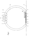
- FIG. 1 shows a schematic representation of the US test device according to the invention.
- the test device To generate the horizontal alternating magnetic field, the test device has a ring yoke 1 and an alternating field coil 2 as magnets. Between the pole pieces 3, 4 of the magnet 1, the coil system, here designed as a transmitting and receiving meander 5, is arranged.
- the coil system 5 is held by a non-magnetic transducer carrier 6, for. B. plastic.
- the workpiece 7 to be tested moves just below the coil system 5 relative to the test device.
- a ferromagnetic coupling piece 8 is arranged on the side of the coil system 5 facing away from the test object. This covers part of the coil system 5, here in this illustration, for example, about 50% of the width.
- the distance between coupling piece 8 / coil system 5 and also the distance between coupling piece 8 / pole shoe 4 can be changed.
- the variation range for the first-mentioned distance is in the range of 0-1 mm and for the second-mentioned distance in the range of 0-10 mm.
- FIGS. 2-5 show the A-scan with a horizontal magnetic field without the coupling according to the invention.
- the first area of the pulse train is the area 10 of the forced oscillation.
- the subsequent area is area 11 of the recovery phase of the receiving system.
- the sum of both is the dead zone area 12, which cannot be used for signal evaluation.
- an artificial error 13 was sounded, which was arranged far enough away that it could also be identified with the very wide dead zone 12.
- FIG. 3 The improvement according to the invention is shown in FIG. 3, in which the area of the recovery phase 11 was almost compensated for by an optimal inductive coupling and the remaining dead zone 12.1 practically coincides with the area of the forced oscillation 10.
- the magnetic current profile 14, 14.1 has also been plotted in addition to the test image.
- the magnetic current curve 14 is optimal in terms of compensation and the runtime spread Fig. 4b clearly shows the greatly shortened dead zone 12.1 and the clearly identifiable error echo 13.1.
- the edge echo 15 is also shown in this illustration.
- the situation is shown in Fig. 5a, which results when the magnetic current profile 14.1 is inverted. This is equivalent to a change in the magnetic polarity of the ring magnet 1.
- the dead zone 12.3 increases again considerably and the test sensitivity is deteriorated so much that the false echo 13.1 can no longer be recognized.
- the edge echo 15 can still be clearly identified.
Landscapes
- Physics & Mathematics (AREA)
- Biochemistry (AREA)
- Health & Medical Sciences (AREA)
- Life Sciences & Earth Sciences (AREA)
- Chemical & Material Sciences (AREA)
- Analytical Chemistry (AREA)
- General Health & Medical Sciences (AREA)
- General Physics & Mathematics (AREA)
- Immunology (AREA)
- Pathology (AREA)
- Acoustics & Sound (AREA)
- Electromagnetism (AREA)
- Investigating Or Analyzing Materials By The Use Of Ultrasonic Waves (AREA)
Description
Die Erfindung betrifft ein Verfahren zum Prüfen ferromagnetischer Werkstücke mittels Ultraschallwellen gemäß dem Gattungsbegriff des Hauptanspruches.The invention relates to a method for testing ferromagnetic workpieces by means of ultrasonic waves according to the preamble of the main claim.
Bei der elektrodynamischen Ultraschallprüfung mit gekoppelten Sende-Empfangssystemen kommt es aufgrund von induktiven Kopplungen während und direkt nach dem Senden zu einer übersteuerung des Empfangssystems. Für eine gewisse Zeit nach dem Senden können keine Ultraschallsignale empfangen werden. Da man auch prüfkopfnahe Fehler im Werkstück nachweisen und geringe Wanddicken messen will, ist man bestrebt, die sogenannte Tot-Zone möglichst klein zu halten.In the case of the electrodynamic ultrasound test with coupled transceiver systems, the receiving system is overloaded due to inductive couplings during and immediately after transmission. Ultrasound signals cannot be received for a period of time after transmission. Since you also want to detect defects in the workpiece close to the test head and measure small wall thicknesses, you endeavor to keep the so-called dead zone as small as possible.
Zur Verringerung der Tot-Zone sind verschiedene Maßnahmen ergriffen worden, so zum Beispiel die Unterdrückung der nicht erwünschten Ultraschallanregungen durch den Einbau von schalldämpfenden Mitteln (DE 38 34 248).Various measures have been taken to reduce the dead zone, for example the suppression of undesired ultrasonic excitations by the installation of sound-absorbing means (DE 38 34 248).
Damit war es möglich, bei der elektrodynamischen Fehlerprüfung (Winkeleinschallung) die Tot-Zone auf 15 bis 12 Mikrosekunden zu verkürzen.This made it possible to shorten the dead zone to 15 to 12 microseconds during the electrodynamic error test (angle scan).
Aufgabe der Erfindung ist es, ein verbessertes Verfahren zum Prüfen von ferromagnetischen Werkstücken mi-ttels Ultraschallwellen mit einem gekoppelten Sende- und Empfangsspulensystem anzugeben, mit dem prüfkopfnahe Fehler bei Winkeleinschallung im Bereich von < 10 mm nachweisbar und Wanddicken < 2 mm gemessen werden können.The object of the invention is to provide an improved method for testing ferromagnetic workpieces by means of ultrasound waves with a coupled transmitting and receiving coil system, with which errors close to the probe in the case of angular irradiation in the range of <10 mm and wall thicknesses <2 mm can be measured.
Diese Rufgabe wird mit den im kennzeichnenden Teil des Hauptanspruches angegebenen Merkmalen gelöst. Vorteilhafte Weiterbildungen sowie eine Vorrichtung zur Durchführung des Verfahrens sind Bestandteil von Unteransprüchen.This call is solved with the features specified in the characterizing part of the main claim. Advantageous further developments and a device for carrying out the method are part of subclaims.
Zum besseren Verständnis der bisher vorgenommen totzonenverkürzenden Maßnahmen ist es zweckmäßig, die Tot-Zone in drei Bereiche zu unterteilen:
- Einen ersten Bereich, in dem der Sendestrom auf die Sendespulen gegeben wird. Hier wird über den Trafoeffekt des Empfangssystems zu erzwungenen, übersteuerten Schwingungen angeregt.
- Einen zweiten Bereich, die Erholungsphase des Empfangssystems. Hier fängt das System bedingt an zu arbeiten, indem es von der letzten durch den Sendestrom erzwungenen Übersteuerung langsam auf die Nullinie einschwingt.
- Einen dritten Bereich, wo das Gesamtsystem durch Ultraschallschwingungen selbst angeregt wird, wobei die beiden erstgenannten Bereiche elektrisch bedingt sind.
- A first area in which the transmission current is applied to the transmission coils. Here, forced, overdriven vibrations are stimulated via the transformer effect of the receiving system.
- A second area, the recovery phase of the reception system. Here the system begins to work conditionally by slowly moving from the last overdrive forced by the transmission current to the zero line.
- A third area, where the entire system itself is excited by ultrasonic vibrations, the first two areas being electrically dependent.
Eine Verkürzung der Tot-Zone bei gekoppelten Sende-Empfangsspulensystemen kann über die Unterdrückung unerwünschter Ultraschallanregung im Prüfkopf selbst (Bereich 3) hinaus nur über den zweiten Bereich der Tot-Zone, die Erholungsphase des Empfangssystems erfolgen. Dazu wird vorgeschlagen, durch eine geeignete elektrische oder induktive Einkopplung in das Empfangssystem das Ausklingen zu dämpfen, wobei die im Empfangssystem erfolgte Einkopplung der letzten durch den Sendestrom erzeugten übersteuerung entgegengerichtet ist. Mit dieser Maßnahme wird die Tot-Zone z.B. bei einer Winkeleinschallung auf Werte von kleiner 7 Mikrosekunden reduziert.A shortening of the dead zone in the case of coupled transmitting / receiving coil systems can, beyond the suppression of unwanted ultrasonic excitation in the test head itself (area 3), only take place over the second area of the dead zone, the recovery phase of the receiving system. For this purpose, it is proposed to dampen the decay by means of a suitable electrical or inductive coupling into the receiving system, the coupling occurring in the receiving system being counter to the last overdrive generated by the transmission current. With this measure, the dead zone is e.g. reduced to values of less than 7 microseconds in the case of angular irradiation.
Bei einer elektrischen Einkopplung muß zunächst der zeitliche Amplitudenverlauf des in den Empfangskreis eingekoppelten Singals an den Verlauf der Erholungsphase des Empfangssystems (Bereich 2) angepaßt werden. Ist der Amplitudenverlauf ermittelt, so muß dieser mit jedem Sendeimpuls entsprechend zeitsynchronisiert in das Empfangssystem eingespeist werden. Durch geeignete, bekannte elektronische Schaltungen muß die für die elektrische Einkopplung erforderliche Signalquelle vor während des ersten Bereichs der Tot-Zone im Empfangssystem induzierten Hochspannungen geschützt werden.In the case of an electrical coupling, the temporal amplitude profile of the signal coupled into the receiving circuit must first be adapted to the profile of the recovery phase of the receiving system (area 2). Once the amplitude curve has been determined, it must be fed into the receiving system in a time-synchronized manner with each transmission pulse. The signal source required for the electrical coupling must be protected from high voltages induced in the receiving system during the first region of the dead zone by means of suitable, known electronic circuits.
Die vorgeschlagene Maßnahme zur Dämpfung der übersteuerung beim Ausklingen ist dann besonders wirksam, wenn ein Teil des magnetischen Wechselfeldes, das zur koppelmittelfreien, magnetostriktiven Ultraschallanregung erforderlich ist, in das Spulensystem induktiv eingekoppelt wird.The proposed measure for damping the overdrive when decaying is particularly effective when part of the alternating magnetic field, which is required for coupling-free, magnetostrictive ultrasound excitation, is inductively coupled into the coil system.
Für die praktische Realisierung wird eine Prüfvorrichtung vorgeschlagen, bei der die beiden Polschuhe des Magnetjoches direkt an den Sender- und Empfangsmäander anliegen und auf der prüflingsabgewandten Seite der Mäander ein mit einem Polschuh des Wechselfeldmagneten magnetisch leitend verbundenes ferromagnetisches Koppelstück angeordnet ist. Dieses Koppelstück wird vorzugsweise aus einem an sic-h bekannten weichmagnetischen Pulververbundwerkstoff mit geringer elektrischer Leitfähigkeit unter dem Handelsnamen Corovac (siehe Prospekt der Firma Vacuumschmelze/Hanau, Ausgabe 3187) hergestellt und überdeckt ein Drittel bis zwei Drittel des PoLschuhabstandes bzw. der Mäanderrückseite. Die gewünschte Tot-Zonen-Verringerung wird aber nur dann erreicht, wenn die im Empfangssystem hervorgerufene Induktion amplitudenmässig so abgestimmt ist, daß sie durch den Sendestrom verursachte ausklingende Übersteuerung kompensiert und das Nachschwingen des Empfangssystems dämpft. Die Amplitude der induktiven Einkopplung im Empfangssystem kann beeinflußt werden durch
- die Amplitude und das Anstiegs- bzw. Abklingverhalten des magnetischen Wechselfeldes
- die Wahl des Werkstoffs des Koppelstückes
- die Veränderung des Abstandes Koppelteil zu Mäanderrückseite
- die Veränderung des Abstandes Koppelteil zu Polschuh.
- the amplitude and the rise or decay behavior of the magnetic alternating field
- the choice of the material of the coupling piece
- the change in the distance between the coupling part and the meander back
- the change in the distance between the coupling part and the pole piece.
Für die beiden letztgenannten Einflußfaktoren wird vorzugsweise für den Abstand Koppelstück/Mäanderrückseite ein Wert von 0,5 mm und für den Abstand Koppelstück zu Polschuh ein Wert gegen 0 mm vorgeschlagen. Dies bedeutet, daß im Sonderfall das Koppelstück direkt am Polschuh anliegt. Bei dieser Konstellation ist aber darauf zu achten, daß das induktiv eingekoppelte Magnetfeld nicht zu stark wird, so daß die übersteuerung überkompensiert wird und negative Werte annimmt. Besonders vorteilhaft ist die Prüfvorrichtung dann, wenn das Magnetjoch als Ringjoch ausgebildet ist.For the latter two influencing factors, a value of 0.5 mm is preferably proposed for the distance between the coupling piece / meander back and a value against 0 mm for the distance between the coupling piece and the pole shoe. This means that in a special case the coupling piece lies directly on the pole piece. In this constellation, however, care must be taken that the inductively coupled magnetic field does not become too strong, so that the overdrive is overcompensated and takes on negative values. The test device is particularly advantageous when the magnetic yoke is designed as a ring yoke.
In der Zeichnung werden anhand einiger Darstellungen das erfindungsgemäße Verfahren sowie die erfindungsgemäße Vorrichtung näher erläutert.In the drawing, the method according to the invention and the device according to the invention are explained in more detail with the aid of some representations.
Es zeigen:
Figur 1- eine schematische Darstellung der erfindungsgemäßen US-Prüfvorrichtung
Figur 2- ein A-Bild mit horizontalem Magnetfeld aber ohne Einkopplung
Figur 3- wie Fig. 2 jedoch mit optimaler induktiver Einkoppelung
- Figur 4a
- Darstellung des Magnetstromverlaufes mit synchronisierter elektrodynamischer Prüfung und optimaler induktiver Einkoppelung
- Figur 4b
- wie Fig. 4a aber in laufzeitmäßig gespreizter Darstellung
- Figur 5a
- wie Fig. 4a aber mit entgegengesetzt gerichteter induktiver Einkoppelung
- Figur 5b
- wie Fig. 5a aber in laufzeitmäßig gespreizter Darstellung.
- Figure 1
- is a schematic representation of the US test device according to the invention
- Figure 2
- an A-scan with a horizontal magnetic field but without coupling
- Figure 3
- like FIG. 2, but with optimal inductive coupling
- Figure 4a
- Representation of the magnetic current curve with synchronized electrodynamic testing and optimal inductive coupling
- Figure 4b
- like Fig. 4a but in terms of runtime spread representation
- Figure 5a
- like FIG. 4a but with oppositely directed inductive coupling
- Figure 5b
- like Fig. 5a but in terms of runtime spread representation.
Figur 1 zeigt in einer schematischen Darstellung die erfindungsgemäße US-Prüfvorrichtung. Zur Erzeugung des horizontalen magnetischen Wechselfeldes weist die Prüfvorrichtung als Magneten ein Ringjoch 1 und eine Wechselfeldspule 2 auf. Zwischen den Polschuhen 3,4 des Magneten 1 ist das Spulensystem, hier ausgebildet als Sende- und Empfangsmäander 5, angeordnet. Das Spulensystem 5 wird gehalten durch einen unmagnetischen Wandlerträger 6, z. B. Kunststoff. Das zu prüfende Werkstück 7 bewegt sich dicht unterhalb des Spulensystems 5 relativ zur Prüfvorrichtung. Für die erfindungsgemäße Einkoppelung ist auf der prüflingsabgewandten Seite des Spulensystems 5 ein ferromagnetisches Koppelstück 8 angeordnet. Dieses bedeckt einen Teil des Spulensystems 5, hier in dieser Darstellung beispielsweise etwa 50 % der Breite. Um eine optimale Kompensation der übersteuerung des Empfangssystems zu erreichen, ist der Abstand Kopplungsstück 8/Spulensystem 5 und auch der Abstand Kopplungsstück 8/Polschuh 4 veränderbar. Für den erstgenannten Abstand liegt die Variationsbreite im Bereich von 0 - 1 mm und für den zweitgenannten Abstand im Bereich von 0 - 10 mm.Figure 1 shows a schematic representation of the US test device according to the invention. To generate the horizontal alternating magnetic field, the test device has a
Die Wirkung der vorgeschlagenen induktiven Einkoppelung ist in den nachfolgenden Figuren 2 - 5 dargestellt. Figur 2 zeigt das A-Bild mit horizontalem Magnetfeld ohne die erfindungsgemäße Einkoppelung. Der erste Bereich der Impulsabfolge ist der Bereich 10 der erzwungenen Schwingung. Der anschließende Bereich ist der Bereich 11 der Erholungsphase des Empfangssystems. Die Summe aus beiden ist der Totzonenbereich 12, der für eine Signalauswertung nicht genutzt werden kann. In diesem Beispiel wurde ein künstlicher Fehler 13 angeschallt, der weit genug entfernt angeordnet war, so daß er auch mit der sehr breiten Totzone 12 identifiziert werden konnte. Die erfindungsgemäße Verbesserung zeigt Fig. 3, bei der durch eine optimale induktive Einkoppelung der Bereich der Erholungsphase 11 nahezu gegen Null kompensiert wurde und die verbleibende Totzone 12.1 praktisch mit dem Bereich der erzwungenen Schwingung 10 zusammenfällt.The effect of the proposed inductive coupling is shown in the following FIGS. 2-5. Figure 2 shows the A-scan with a horizontal magnetic field without the coupling according to the invention. The first area of the pulse train is the area 10 of the forced oscillation. The subsequent area is area 11 of the recovery phase of the receiving system. The sum of both is the
In den Figuren 4a und 5a ist zusätzlich zum Prüfbild der Magnetstromverlauf 14, 14.1 mit aufgetragen worden. In Fig. 4a ist der Magnetstromverlauf 14 optimal im Sinne der Kompensation und das laufzeitmäßig gespreizte Bild Fig. 4b zeigt deutlich die stark verkürzte Totzone 12.1 und das eindeutig identifizierbare Fehlerecho 13.1. Der Vollständigkeit halber ist in dieser Darstellung auch noch das Kantenecho 15 mit abgebildet. Demgegenüber ist in Fig. 5a die Situation dargestellt, die sich ergibt, wenn der Magnetstromverlauf 14.1 invertiert wird. Das ist gleichbedeutend mit einem Wechsel der magnetischen Polung des Ringmagneten 1. Dann vergrößert sich die Totzone 12.3 wieder ganz erheblich und die Prüfempfindlichkeit wird so stark verschlechtert, daß das Fehlerecho 13.1 nicht mehr zu erkennen ist. Unverändert dagegen ist das Kantenecho 15 eindeutig zu identifizieren.4a and 5a, the magnetic
Claims (8)
- Process for testing ferromagnetic workpieces by means of ultrasonic waves whereby an alternating magnetizing field is produced parallel to a surface or a workpiece, in a said workpiece, by means of a magnet system, energized by an alternating current, applied onto a surface of a workpiece, and high-frequency transmission pulses are released, by means of a coupled transmission-reception system disposed close to a surface of a workpiece concerned, said pulses leading to over-excitation of a receiver system, as a result of inductive coupling, after transmission,
wherein
drop-off in a recovery phase of a receiver system is damped by means of suitable electrical or inductive coupling. - Process in accordance with claim 1,
wherein
part of an alternating magnetic field is inductively coupled into a coil system, whereby induction caused in a receiver system by an alternating field acts against over-excitation caused by a transmission current. - Device for carrying out a process in accordance with claim 1,
comprising a magnet yoke (1) and a coupled transmission-reception coil system, with transmission and reception loops (5) being inserted one into another, disposed between pole pieces (3, 4) of a magnet yoke, wherein both of two pole pieces (3, 4) of a magnet-yoke (1) lie close up against transmission and reception loops (5) and a ferromagnetic coupling piece (8), magnetically conductively connected to a pole piece (4) of alternating-field magnets, is disposed on a side of a loop (5) facing away from a test-piece. - Device in accordance with claim 3,
wherein
a ferromagnetic coupling piece (8) covers a third to two thirds of a separation between pole pieces (3, 4) or a rear side of a loop (5). - Device in accordance with claim 3 or 4,
wherein
a separation between a ferromagnetic coupling piece (8) and a rear side of a loop (5) is from 0 to 1 mm. - Device in accordance with claim 3 or 4,
wherein
a separation between a ferromagnetic coupling piece (8) and a pole piece (4) is from 0 to 10 mm. - Device in accordance with any one of claims 3 to 6,
wherein
a ferromagnetic coupling piece (8) is produced from a known lightly magnetic connecting powder material with slight electrical conductivity. - Device in accordance with any one of claims 3 to 7,
wherein
a magnet yoke is developed as a circular yoke (1).
Applications Claiming Priority (2)
| Application Number | Priority Date | Filing Date | Title |
|---|---|---|---|
| DE4130935A DE4130935A1 (en) | 1991-09-13 | 1991-09-13 | METHOD AND DEVICE FOR TESTING FERROMAGNETIC WORKPIECES BY MEANS OF ULTRASONIC WAVES |
| DE4130935 | 1991-09-13 |
Publications (2)
| Publication Number | Publication Date |
|---|---|
| EP0532142A1 EP0532142A1 (en) | 1993-03-17 |
| EP0532142B1 true EP0532142B1 (en) | 1996-02-14 |
Family
ID=6440819
Family Applications (1)
| Application Number | Title | Priority Date | Filing Date |
|---|---|---|---|
| EP92250255A Expired - Lifetime EP0532142B1 (en) | 1991-09-13 | 1992-09-10 | Method and apparatus for ultrasonic testing of ferromagnetic work-pieces |
Country Status (2)
| Country | Link |
|---|---|
| EP (1) | EP0532142B1 (en) |
| DE (2) | DE4130935A1 (en) |
Families Citing this family (2)
| Publication number | Priority date | Publication date | Assignee | Title |
|---|---|---|---|---|
| DE59510950D1 (en) * | 1994-04-14 | 2004-11-11 | Fraunhofer Ges Forschung | Device and method for detecting the test head lift during the non-destructive examination of metallic materials with electromagnetic ultrasonic transducers |
| DE10259891B3 (en) | 2002-12-20 | 2004-04-15 | Fraunhofer-Gesellschaft zur Förderung der angewandten Forschung e.V. | Electromagnetic ultrasonic transducer for couplant-free non-destructive examination of workpieces has an additional flux conductor to improve transmission and receipt of HF electromagnetic waves into a workpiece being tested |
Family Cites Families (5)
| Publication number | Priority date | Publication date | Assignee | Title |
|---|---|---|---|---|
| SE445616B (en) * | 1978-11-07 | 1986-07-07 | Studsvik Energiteknik Ab | PROCEDURE TO INTRODUCE ELECTROMAGNETIC ULTRA SOUND IN ELECTRICALLY CONDUCTIVE MATERIALS IN THE EVENT OF DIFFERENT TESTING AND DEVICE FOR CARRYING OUT THE PROCEDURE |
| DE3029036A1 (en) * | 1980-07-31 | 1982-03-04 | Mannesmann AG, 4000 Düsseldorf | DEVICE FOR TESTING MATERIALS |
| DE3123935C2 (en) * | 1981-06-16 | 1985-03-28 | Nukem Gmbh, 6450 Hanau | Electrodynamic converter |
| DE3834248A1 (en) * | 1988-10-05 | 1990-04-12 | Mannesmann Ag | ELECTRODYNAMIC CONVERTER HEAD |
| DE3904440A1 (en) * | 1989-02-10 | 1990-08-23 | Mannesmann Ag | Electrodynamic transducer head |
-
1991
- 1991-09-13 DE DE4130935A patent/DE4130935A1/en not_active Ceased
-
1992
- 1992-09-10 DE DE59205342T patent/DE59205342D1/en not_active Expired - Fee Related
- 1992-09-10 EP EP92250255A patent/EP0532142B1/en not_active Expired - Lifetime
Also Published As
| Publication number | Publication date |
|---|---|
| DE4130935A1 (en) | 1993-03-25 |
| EP0532142A1 (en) | 1993-03-17 |
| DE59205342D1 (en) | 1996-03-28 |
Similar Documents
| Publication | Publication Date | Title |
|---|---|---|
| DE3834248C2 (en) | ||
| AT390519B (en) | METHOD AND TEST DEVICE FOR THE CONTACTLESS DETERMINATION OF THE AREA WEIGHT OR THE THICKNESS OF THIN MATERIAL, SUCH AS PAPER, FILM OR SIMILAR | |
| EP0200183B1 (en) | Method and device for non-destructive testing of ferromagnetic material | |
| DE69321141T2 (en) | NOISE REDUCTION IN A MAGNETOSTRICTIVE POSITION SENSOR BY DETERMINING A VALID TIME RANGE FOR TRANSMITTING ACOUSTIC REFERENCE IMPULSES | |
| DE2732543A1 (en) | DEVICE AND METHOD FOR MONITORING A BORDER LINE | |
| DE10136628B4 (en) | Ultrasonic transducer for emitting and receiving ultrasonic waves by means of a membrane, method and control device for operating the ultrasonic transducer, and use of the ultrasonic transducer | |
| EP0746775A1 (en) | Identification tag operating with acoustic surface waves | |
| EP0028397B1 (en) | Method of eliminating the influence of remanence in receiving systems and device for carrying out the method | |
| EP0378287A1 (en) | Process for detecting flaws in oblong work pieces | |
| DE69805871T2 (en) | Length measuring device using a magnetostrictive delay line | |
| DE3003961C2 (en) | Method and device for detecting inhomogeneities in magnetizable materials | |
| EP0532142B1 (en) | Method and apparatus for ultrasonic testing of ferromagnetic work-pieces | |
| DE4322849C1 (en) | Method for determining the propagation time (delay time) of sound signals, and a sound-wave propagation-time determining device | |
| EP1572382B1 (en) | Electromagnetic ultrasound converter | |
| DE3904440C2 (en) | ||
| EP1204878B1 (en) | Method for generating measurement signals in magnetic fields | |
| EP0579255B1 (en) | Ultrasonic test head | |
| DE2657957C2 (en) | Device for ultrasonic testing of workpieces | |
| DE3511768C2 (en) | Electromagnetic transducer | |
| EP0892285B1 (en) | Method and arrangement for electromagnetic object detection | |
| EP3964832A1 (en) | Measuring method and measuring arrangement for interference suppression of a received signal of an emat converter | |
| DE4414746A1 (en) | Transceiver circuit for an acoustic pulse echo distance measuring system | |
| DE102004025388B4 (en) | Determining position and movement parameters of object, e.g. machine part, by determining movement parameters that have differential relation to position and/or first movement parameters | |
| DE3012187C2 (en) | Device for correcting the reception sensitivity of an electromagnetic ultrasonic probe | |
| DE10016468C2 (en) | Method and device for measuring the transit time of sound pulses in a magnetoelastic workpiece |
Legal Events
| Date | Code | Title | Description |
|---|---|---|---|
| PUAI | Public reference made under article 153(3) epc to a published international application that has entered the european phase |
Free format text: ORIGINAL CODE: 0009012 |
|
| AK | Designated contracting states |
Kind code of ref document: A1 Designated state(s): DE FR GB IT |
|
| 17P | Request for examination filed |
Effective date: 19930128 |
|
| 17Q | First examination report despatched |
Effective date: 19950721 |
|
| GRAA | (expected) grant |
Free format text: ORIGINAL CODE: 0009210 |
|
| AK | Designated contracting states |
Kind code of ref document: B1 Designated state(s): DE FR GB IT |
|
| PG25 | Lapsed in a contracting state [announced via postgrant information from national office to epo] |
Ref country code: IT Free format text: LAPSE BECAUSE OF FAILURE TO SUBMIT A TRANSLATION OF THE DESCRIPTION OR TO PAY THE FEE WITHIN THE PRESCRIBED TIME-LIMIT;WARNING: LAPSES OF ITALIAN PATENTS WITH EFFECTIVE DATE BEFORE 2007 MAY HAVE OCCURRED AT ANY TIME BEFORE 2007. THE CORRECT EFFECTIVE DATE MAY BE DIFFERENT FROM THE ONE RECORDED. Effective date: 19960214 Ref country code: GB Effective date: 19960214 |
|
| ET | Fr: translation filed | ||
| REF | Corresponds to: |
Ref document number: 59205342 Country of ref document: DE Date of ref document: 19960328 |
|
| GBV | Gb: ep patent (uk) treated as always having been void in accordance with gb section 77(7)/1977 [no translation filed] |
Effective date: 19960214 |
|
| PLBE | No opposition filed within time limit |
Free format text: ORIGINAL CODE: 0009261 |
|
| STAA | Information on the status of an ep patent application or granted ep patent |
Free format text: STATUS: NO OPPOSITION FILED WITHIN TIME LIMIT |
|
| 26N | No opposition filed | ||
| PGFP | Annual fee paid to national office [announced via postgrant information from national office to epo] |
Ref country code: DE Payment date: 19991018 Year of fee payment: 8 |
|
| PGFP | Annual fee paid to national office [announced via postgrant information from national office to epo] |
Ref country code: FR Payment date: 20000831 Year of fee payment: 9 |
|
| PG25 | Lapsed in a contracting state [announced via postgrant information from national office to epo] |
Ref country code: DE Free format text: LAPSE BECAUSE OF NON-PAYMENT OF DUE FEES Effective date: 20010601 |
|
| PG25 | Lapsed in a contracting state [announced via postgrant information from national office to epo] |
Ref country code: FR Free format text: LAPSE BECAUSE OF NON-PAYMENT OF DUE FEES Effective date: 20020531 |
|
| REG | Reference to a national code |
Ref country code: FR Ref legal event code: ST |