EP0028397B1 - Method of eliminating the influence of remanence in receiving systems and device for carrying out the method - Google Patents
Method of eliminating the influence of remanence in receiving systems and device for carrying out the method Download PDFInfo
- Publication number
- EP0028397B1 EP0028397B1 EP80106651A EP80106651A EP0028397B1 EP 0028397 B1 EP0028397 B1 EP 0028397B1 EP 80106651 A EP80106651 A EP 80106651A EP 80106651 A EP80106651 A EP 80106651A EP 0028397 B1 EP0028397 B1 EP 0028397B1
- Authority
- EP
- European Patent Office
- Prior art keywords
- magnetic flux
- pulses
- receivers
- viii
- magnetic field
- Prior art date
- Legal status (The legal status is an assumption and is not a legal conclusion. Google has not performed a legal analysis and makes no representation as to the accuracy of the status listed.)
- Expired
Links
- 238000000034 method Methods 0.000 title claims description 27
- 230000005291 magnetic effect Effects 0.000 claims description 66
- 230000004907 flux Effects 0.000 claims description 41
- 239000003302 ferromagnetic material Substances 0.000 claims description 7
- 230000006698 induction Effects 0.000 claims description 4
- 238000001514 detection method Methods 0.000 claims 1
- 230000005415 magnetization Effects 0.000 description 13
- 238000005259 measurement Methods 0.000 description 10
- 238000010586 diagram Methods 0.000 description 9
- 210000003128 head Anatomy 0.000 description 5
- 238000011156 evaluation Methods 0.000 description 4
- 230000005347 demagnetization Effects 0.000 description 3
- 239000000853 adhesive Substances 0.000 description 2
- 230000001070 adhesive effect Effects 0.000 description 2
- 230000000694 effects Effects 0.000 description 2
- 239000000463 material Substances 0.000 description 2
- 210000000214 mouth Anatomy 0.000 description 2
- 230000035945 sensitivity Effects 0.000 description 2
- 230000002411 adverse Effects 0.000 description 1
- 230000001419 dependent effect Effects 0.000 description 1
- 238000011161 development Methods 0.000 description 1
- 230000018109 developmental process Effects 0.000 description 1
- 239000011521 glass Substances 0.000 description 1
- 230000017525 heat dissipation Effects 0.000 description 1
- 230000001788 irregular Effects 0.000 description 1
- 239000010410 layer Substances 0.000 description 1
- 229910000595 mu-metal Inorganic materials 0.000 description 1
- 230000000737 periodic effect Effects 0.000 description 1
- 238000007493 shaping process Methods 0.000 description 1
- 239000002356 single layer Substances 0.000 description 1
Images
Classifications
-
- A—HUMAN NECESSITIES
- A61—MEDICAL OR VETERINARY SCIENCE; HYGIENE
- A61B—DIAGNOSIS; SURGERY; IDENTIFICATION
- A61B5/00—Measuring for diagnostic purposes; Identification of persons
- A61B5/45—For evaluating or diagnosing the musculoskeletal system or teeth
- A61B5/4528—Joints
-
- A—HUMAN NECESSITIES
- A61—MEDICAL OR VETERINARY SCIENCE; HYGIENE
- A61B—DIAGNOSIS; SURGERY; IDENTIFICATION
- A61B5/00—Measuring for diagnostic purposes; Identification of persons
- A61B5/103—Measuring devices for testing the shape, pattern, colour, size or movement of the body or parts thereof, for diagnostic purposes
- A61B5/11—Measuring movement of the entire body or parts thereof, e.g. head or hand tremor or mobility of a limb
- A61B5/1113—Local tracking of patients, e.g. in a hospital or private home
- A61B5/1114—Tracking parts of the body
-
- A—HUMAN NECESSITIES
- A61—MEDICAL OR VETERINARY SCIENCE; HYGIENE
- A61B—DIAGNOSIS; SURGERY; IDENTIFICATION
- A61B5/00—Measuring for diagnostic purposes; Identification of persons
- A61B5/103—Measuring devices for testing the shape, pattern, colour, size or movement of the body or parts thereof, for diagnostic purposes
- A61B5/11—Measuring movement of the entire body or parts thereof, e.g. head or hand tremor or mobility of a limb
- A61B5/1126—Measuring movement of the entire body or parts thereof, e.g. head or hand tremor or mobility of a limb using a particular sensing technique
- A61B5/1127—Measuring movement of the entire body or parts thereof, e.g. head or hand tremor or mobility of a limb using a particular sensing technique using markers
-
- A—HUMAN NECESSITIES
- A61—MEDICAL OR VETERINARY SCIENCE; HYGIENE
- A61C—DENTISTRY; APPARATUS OR METHODS FOR ORAL OR DENTAL HYGIENE
- A61C19/00—Dental auxiliary appliances
- A61C19/04—Measuring instruments specially adapted for dentistry
- A61C19/045—Measuring instruments specially adapted for dentistry for recording mandibular movement, e.g. face bows
-
- G—PHYSICS
- G01—MEASURING; TESTING
- G01R—MEASURING ELECTRIC VARIABLES; MEASURING MAGNETIC VARIABLES
- G01R33/00—Arrangements or instruments for measuring magnetic variables
- G01R33/02—Measuring direction or magnitude of magnetic fields or magnetic flux
- G01R33/06—Measuring direction or magnitude of magnetic fields or magnetic flux using galvano-magnetic devices
- G01R33/07—Hall effect devices
-
- A—HUMAN NECESSITIES
- A61—MEDICAL OR VETERINARY SCIENCE; HYGIENE
- A61B—DIAGNOSIS; SURGERY; IDENTIFICATION
- A61B2562/00—Details of sensors; Constructional details of sensor housings or probes; Accessories for sensors
- A61B2562/04—Arrangements of multiple sensors of the same type
- A61B2562/046—Arrangements of multiple sensors of the same type in a matrix array
-
- A—HUMAN NECESSITIES
- A61—MEDICAL OR VETERINARY SCIENCE; HYGIENE
- A61B—DIAGNOSIS; SURGERY; IDENTIFICATION
- A61B5/00—Measuring for diagnostic purposes; Identification of persons
- A61B5/68—Arrangements of detecting, measuring or recording means, e.g. sensors, in relation to patient
- A61B5/6801—Arrangements of detecting, measuring or recording means, e.g. sensors, in relation to patient specially adapted to be attached to or worn on the body surface
- A61B5/6813—Specially adapted to be attached to a specific body part
- A61B5/6814—Head
Definitions
- the invention relates to a method for eliminating the influence of remanence in receiving systems, in which one or more magnetic flux sensors made of ferromagnetic material, preferably Hall antennas provided with antennas, are provided for detecting a magnetic flux originating from a magnetic field generator or a change in magnetic flux. Furthermore, the invention relates to the use of this method and an apparatus for carrying it out.
- a magnetic field generator e.g. a permanent magnet
- a magnetic flux sensor system with Hall generators and antennas arranged on the patient's head and at a distance from the magnetic field generator.
- the magnetic field changes occurring when the lower jaw moves are recorded by the sensor system in all three movement levels and evaluated by an electronic evaluation device.
- the structure of such a device is described, for example, in the German patent application according to DE-A-2 852 764 published after the priority date of the present application or in DE-A-2 814 551.
- the object of the present invention is to provide an improved method for eliminating the influence of remanence as well as an apparatus for carrying out the method, which is independent of the earth's magnetic field and other, possibly disturbing field influences, such as e.g. of a measuring magnet or the like, works and with which clear and reproducible measurement results can be achieved.
- the set goal is achieved according to the invention with the method according to claim 1 or the device according to claim 8.
- the use of the method is defined in claim 7.
- the magnetic flux sensors are included before a measured value acquisition DC magnetic field pulses applied.
- the magnetization thus serves to prepare for a measurement, in order then to have the same starting position for the measurement.
- magnetization pulses By applying magnetization pulses to the magnetic pickup system in the pulse intervals, formed by short DC pulses of a certain pulse size, as suggested, it is ensured that the output voltages at the magnetic flux pickups are subject to the same initial conditions. After the intermediate pulse is repeated after each measuring pulse with which the magnetic flux transducers are applied, the same initial conditions are always created. After the end of the pulse, the magnetization falls back to the value M ⁇ , which represents the maximum possible remanence of the material used for a magnetic flux sensor. This value is independent of any foreign fields that may occur.
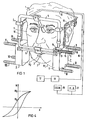
- 1 shows a diagram of a device for determining the location, the position and / or a change in location or position of a point of the lower jaw of a patient.
- 1 denotes the head of a patient and 2 the lower jaw.
- 3 with a permanent magnet serving as a field generator is designated, which is attached within the oral cavity of the patient at any point on the lower jaw by means of suitable adhesives or adhesives.
- the magnetic field generator 3 consists of two identically dimensioned bar magnets, as are described in more detail in the German patent application DE-A-2715106.
- the magnetic field generator 3 generates two irregular, non-rotationally symmetrical magnetic fields M ′′ M 2 , indicated by dashed lines in the figure.
- a magnetic flux sensor arrangement 4 consisting essentially of a frame 5 held on the patient's head 1 and a sensor system with a sensor block 6 and 7 located to the left and right of the lower jaw.
- the frame 5 is designed in a known manner as a combined glasses or head frame and contains several, unspecified joints to adapt to the different head constellations of the patient.
- the two transducer blocks 6 and 7 are rigidly connected to one another by a rod 8 connected to the frame 5.
- Each of the sensor blocks 6, 7 contains four magnetic flux sensors to VIII, which are held in a plastic housing 9, in such a way that they are each parallel to one another.
- the signals recorded by the magnetic flux sensors I to VIII which are described in more detail below, are fed to an electronic evaluation device 11 via multi-core lines 10 and from there to a suitable indicator device 12.
- the magnetic flux sensor I contains a platelet-shaped Hall generator 13 serving as a sensor, on the effective surface of which, on both sides, antenna rods 14 and 15 made of mu-metal are of different lengths.
- a platelet-shaped Hall generator 13 serving as a sensor, on the effective surface of which, on both sides, antenna rods 14 and 15 made of mu-metal are of different lengths.
- the signals generated thereby by the Hall generators are fed to the electronics unit 11 via a preamplifier, which is arranged in the housing 9 and is not shown in the figure, where the signals are then processed for a graphic representation.
- An induction coil 16 is wound in one layer around each magnetic flux sensor.
- the single-layer wrapping of the flux sensors has the advantage that, on the one hand, there is good heat dissipation and, on the other hand, a better magnetic field for magnetization is generated.
- the four coils 16 of each block (6 and 7) are connected in series and connected in parallel with the four others of the other block. As will be explained in more detail later, the coils 16 are supplied with periodic square-wave pulses by a pulse generator 19 via the one wiring harness of a double line 18. 17 denotes a further pulse generator, which controls the Hall generators 13 with pulse-shaped signals via the other wiring harness of the double line 18.
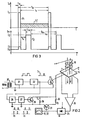
- FIG. 2 shows a control circuit for the Hall generators 13, which is particularly advantageous for very small field strengths, as well as a basic circuit diagram for controlling the coils 16 with pulses.
- An AC transformer 20 generates AC signals with a frequency of 50 Hz, which are first fed to a Schmitt trigger 21 for pulse shaping.
- a monostable multivibrator 22 then supplies control pulses I, in a certain duty cycle, which are then fed to the Hall generator 13 via a transistor 23.
- the pulse signals that can be achieved by the circuit shown now provide information about the size or shape (envelope) of the useful signal which is obtained from the Hall generators 13. In order to convert the pulses into a useful signal, they are first fed to a peak value rectifier 25 via an amplifier 24. The signals obtainable from this can then be evaluated and optically displayed with the aid of a suitable evaluation (computer) and indicator device 11, 12.
- the pulses generated by the clock generator 17 and for example with the aid of the circuit arrangement according to FIG. 2 are denoted by I.
- the pulse width t jS is approximately 0.5 ms with a pulse period T is of 20 ms.
- the ratio of pulse width to pulse interval t is / i s is selected in the present case so that the permitted effective control power of the Hall generator is not exceeded, ie the area labeled F, must not be larger than the area labeled F 1 , that of Control power of the Hall generator corresponds to DC.
- the more extreme the duty cycle, ie the shorter the pulses and the longer the pulse pause are selected the higher the maximum amplitude of the control current can be sets and thus the sensitivity of the Hall generator can be increased.
- the coils 16 are periodically supplied with short DC pulses I 2 with the aid of the pulse generator 19.
- a circuit diagram for generating these pulses is shown in FIG. 2.
- the control pulses I 1 for the Hall generators 13 are fed to a monostable multivibrator 26, with the falling pulse edge of which a further monostable multivibrator 27 is controlled.
- the flip-flop 26 indicates the delay time denoted by t v in the pulse diagram according to FIG. 3 compared to the control pulse I 1 , the flip-flop 27 the pulse width with which the transistor designated 28 in the circuit diagram according to FIG. 2 and thus the magnetization coils 16 are driven .
- the pulses I 2 are supplied synchronously with the control pulses I 1 , in the present case at a frequency of 50 Hz.
- the point in time at which the pulses I 2 are supplied can, in and of itself, be chosen arbitrarily, it only has to lie within the pulse pause i s .
- the pulse height and pulse width are so large that the saturation field strength for the flux sensors (Hall generator and antennas) is achieved with the magnetization pulses induced by the coils 16.
- the magnetization of the antenna system thereby reaches its saturation value M 8 , as shown in FIG. 4, which shows a hysteresis curve of a ferromagnetic material.
- the saturation field strength of the material provided for the transducers can therefore always be achieved by the direct current pulse I 2 supplied periodically in the pulse interval i s .
- the magnetization falls back to the value M r . Since it represents the maximum possible retentivity for the system, this value is independent of any external fields that may occur. After the process has been repeated after each measurement pulse, in this case every 20 ms, it is ensured that the output voltage at the Hall generators 13 is always subject to the same initial conditions.
- the method according to the invention can also be used with a non-pulsed control current.
- a uniform control current the magnetization pulses are then periodically supplied at any point, the control current or the measurement voltage then being blanked out for the duration of the magnetization pulses.
- the coils 16 on each flow sensor I to VIII are geometrically the same, ie they have the same number of turns, diameter and length. If one switches during the measurement time is t to any type of sensors a further short DC pulse 1 3 of defined size on, as is shown in the pulse diagram according to Fig. 3, so magnetic fields are generated at the Hall generators 16 are respectively the same. With the help of matching amplifiers, the Hall generators can be adjusted to the same sensitivity. This measure enables a simplified comparison and also an easier control of the comparison.
- the direct current pulses 1 3 arise by connecting a resistor 30 in parallel via a transistor 31 to the transistor 28. The direct current 1 3 is not present during a measurement.
Landscapes
- Health & Medical Sciences (AREA)
- Life Sciences & Earth Sciences (AREA)
- Oral & Maxillofacial Surgery (AREA)
- Physics & Mathematics (AREA)
- Veterinary Medicine (AREA)
- Engineering & Computer Science (AREA)
- Biomedical Technology (AREA)
- Biophysics (AREA)
- Dentistry (AREA)
- Animal Behavior & Ethology (AREA)
- General Health & Medical Sciences (AREA)
- Public Health (AREA)
- Heart & Thoracic Surgery (AREA)
- Surgery (AREA)
- Molecular Biology (AREA)
- Medical Informatics (AREA)
- Pathology (AREA)
- Physiology (AREA)
- General Physics & Mathematics (AREA)
- Condensed Matter Physics & Semiconductors (AREA)
- Epidemiology (AREA)
- Orthopedic Medicine & Surgery (AREA)
- Rheumatology (AREA)
- Measuring Magnetic Variables (AREA)
- Magnetic Treatment Devices (AREA)
- Measurement Of The Respiration, Hearing Ability, Form, And Blood Characteristics Of Living Organisms (AREA)
- Dental Tools And Instruments Or Auxiliary Dental Instruments (AREA)
- Measurement And Recording Of Electrical Phenomena And Electrical Characteristics Of The Living Body (AREA)
Description
Die Erfindung bezieht sich auf ein Verfahren zur Beseitigung des Einflusses von Remanenz in Empfangssystemen, bei denen zur Erfassung eines von einem Magnetfelderzeuger ausgehenden Magnetflusses bzw. einer Magnetflussänderung ein oder mehrere Magnetflussaufnehmer aus ferromagnetischem Werkstoff, vorzugsweise mit Antennen versehene Hallgeneratoren, vorgesehen sind. Weiterhin bezieht sich die Erfindung auf eine Verwendung dieses Verfahrens sowie eine Vorrichtung zu seiner Durchführung.The invention relates to a method for eliminating the influence of remanence in receiving systems, in which one or more magnetic flux sensors made of ferromagnetic material, preferably Hall antennas provided with antennas, are provided for detecting a magnetic flux originating from a magnetic field generator or a change in magnetic flux. Furthermore, the invention relates to the use of this method and an apparatus for carrying it out.
In Empfangssystemen, bei denen insbesondere relativ kleine Magnetfeldänderungen mit Hilfe von Magnetflussaufnehmern, wie Hallgeneratoren, erfasst werden sollen und bei denen reproduzierbare Messergebnisse mit aus einer Feldflussänderung gewonnenen Signalen zu erzielen sind, dürfen keine störenden, sich auf die Auswertung der Signale nachteilig auswirkenden Remanenzerscheinungen auftreten. Solche störenden Remanenzerscheinungen treten jedoch wegen der in der Regel nicht absolut remanenzfreien ferromagnetischen Materialien der Magnetflussaufnehmer (Hallgeneratoren und gegebenenfalls mit diesen gekuppelte Antennen) bei Magnetfeldänderungen, z.B. bei einer Ortsveränderung des Empfangssystems im Erdmagnetfeld oder bei Annäherung eines Messinstruments mit einem weiteren Magnetfelderzeuger, auf.In reception systems, in which relatively small changes in the magnetic field are to be recorded with the aid of magnetic flux sensors, such as Hall generators, and in which reproducible measurement results can be achieved with signals obtained from a change in the field flux, there should be no disturbing remanent phenomena which have an adverse effect on the evaluation of the signals. Such disturbing remanence phenomena occur, however, due to the ferromagnetic materials of the magnetic flux sensors (Hall generators and possibly antennas coupled to them) which are generally not absolutely non-remanent when magnetic field changes occur, e.g. in the event of a change in location of the receiving system in the earth's magnetic field or when a measuring instrument with another magnetic field generator is approaching.
Ein Anwendungsbeispiel wird in der Gnathologie gesehen, wo man mit Hilfe einer Messvorrichtung die Bewegung des Unterkiefers eines Menschen erfassen und aufzeichnen will. Dabei wird am Unterkiefer eines Patienten ein Magnetfelderzeuger, z.B. ein Permanentmagnet, befestigt und am Kopf des Patienten und in einem Abstand zum Magnetfelderzeuger ein Magnetflussaufnehmersystem mit Hallgeneratoren und Antennen angeordnet. Die bei einer Bewegung des Unterkiefers auftretenden Magnetfeldänderungen werden vom Aufnehmersystem in allen drei Bewegungsebenen erfasst und über eine elektronische Auswerteeinrichtung ausgewertet. Der Aufbau einer solchen Einrichtung ist beispielsweise in der nach dem Prioritätstag der vorliegenden Anmeldung veröffentlichten deutschen Patentanmeldung gemäss DE-A-2 852 764 oder in DE-A-2 814 551 beschrieben.One application example is seen in gnathology, where a measuring device is used to record and record the movement of a person's lower jaw. A magnetic field generator, e.g. a permanent magnet, attached and a magnetic flux sensor system with Hall generators and antennas arranged on the patient's head and at a distance from the magnetic field generator. The magnetic field changes occurring when the lower jaw moves are recorded by the sensor system in all three movement levels and evaluated by an electronic evaluation device. The structure of such a device is described, for example, in the German patent application according to DE-A-2 852 764 published after the priority date of the present application or in DE-A-2 814 551.
Um insbesondere bei solchen Messvorrichtungen eindeutige und reproduzierbare Messergebnisse zu bekommen ist es notwendig, dass keine störenden, den Ausgangspunkt (Nullpunkt) des Messsystems verändernden Remanenzerscheinungen auftreten.In order to obtain clear and reproducible measurement results, particularly with such measuring devices, it is necessary that no disturbing remanent phenomena occur that change the starting point (zero point) of the measuring system.
Nachdem es aber praktisch keine absolut remanenzfreien ferromagnetischen Materialien für die Magnetflussaufnehmer (Hallgeneratoren und Antennen) gibt und auch das Erdmagnetfeld sich störend auf den Messvorgang auswirkt, ist anzustreben, den Einfluss der Remanenz zu beseitigen.However, since there are practically no absolutely non-retentive ferromagnetic materials for the magnetic flux sensors (Hall generators and antennas) and the earth's magnetic field has a disruptive effect on the measurement process, efforts must be made to eliminate the influence of the retentive.
Ein denkbarer Weg zur Beseitigung dieser störenden Remanenzerscheinungen wäre eine Entmagnetisierung der Flussaufnehmer. In der Veröffentlichung «Kuhrt/Lippmann, Hallgeneratoren», Springer-Verlag 1968, Seiten 32, 33, ist ein solcher Weg aufgezeigt. Das Verfahren hierzu besteht darin, dass man ein mangetisches Wechselfeld mit einer Amplitude H > H, auf den ferromagnetischen Werkstoff einwirken lässt und die Amplitude dieses Wechselfeldes langsam zurücknimmt. Die Magnetisierung umfährt so auf immer kleiner werdenden Hystereseschleifen den Koordinatenursprung und erreicht schliesslich bei verschwindender Wechselfeldamplitude den Punkt H = 0, M = 0.A conceivable way of eliminating these disturbing remanent phenomena would be to demagnetize the flux sensors. Such a way is shown in the publication "Kuhrt / Lippmann, Hallgeneratoren", Springer-Verlag 1968, pages 32, 33. The method for this consists in allowing a mangetic alternating field with an amplitude H> H to act on the ferromagnetic material and slowly reducing the amplitude of this alternating field. The magnetization thus circumvents the origin of the coordinate on increasingly smaller hysteresis loops and finally reaches the point H = 0, M = 0 when the alternating field amplitude disappears.
Bei diesem Entmagnetisierungsverfahren, das relativ zeitaufwendig ist, darf kein äusseres Feld einwirken. Eine exakte Entmagnetisierung ist also nur im feldfreien Raum möglich. Um das Erdmagnefeld zu umgehen, ist eine Entmagnetisierung demnach nur senkrecht zum Erdmagnetfeld und ohne Messmagnet durchführbar. Für viele Anwendungsfälle ist dieses Verfahren also nicht geeignet.With this demagnetization process, which is relatively time-consuming, no external field must act. Exact demagnetization is therefore only possible in a field-free room. In order to avoid the earth's magnetic field, demagnetization can therefore only be carried out perpendicular to the earth's magnetic field and without a measuring magnet. This method is therefore not suitable for many applications.
Aufgabe der vorliegenden Erfindung ist es, ein demgegenüber verbessertes Verfahren zur Beseitigung des Einflusses von Remanenz sowie eine Vorrichtung zur Durchführung des Verfahrens anzugeben, das unabhängig vom vorhandenen Erdmagnetfeld und anderen, eventuell störenden Feldeinflüssen, wie z.B. eines Messmagneten od.dgl., arbeitet und mit dem eindeutige und reproduzierbare Messergebnisse zu erzielen sind.The object of the present invention is to provide an improved method for eliminating the influence of remanence as well as an apparatus for carrying out the method, which is independent of the earth's magnetic field and other, possibly disturbing field influences, such as e.g. of a measuring magnet or the like, works and with which clear and reproducible measurement results can be achieved.
Das gestellte Ziel wird gemäss der Erfindung mit dem Verfahren nach Anspruch 1 bzw. der Vorrichtung nach Anspruch 8 erreicht. Die Verwendung des Verfahrens ist in Anspruch 7 definiert.The set goal is achieved according to the invention with the method according to
Im Gegensatz zu einem anderen bekannten Verfahren (AT-B-209 423), welches zur Messung von unter anderem schwachen Gleichfeldern vorgesehen ist und bei welchem das Aufmagnetisieren der Kerne bis zur Sättigungsgrenze zum Messprinzip gehört, werden gemäss der Erfindung die Magnetflussaufnehmer vor einer Messwerterfassung mit Gleichmagnetfeldimpulsen beaufschlagt. Beim erfindungsgemässen Verfahren dient also das Aufmagnetisieren zur Vorbereitung einer Messung, um dann für die Messung jeweils gleiche Ausgangsposition zu haben.In contrast to another known method (AT-B-209 423), which is intended for measuring, among other things, weak DC fields and in which the magnetization of the cores up to the saturation limit is part of the measuring principle, according to the invention, the magnetic flux sensors are included before a measured value acquisition DC magnetic field pulses applied. In the method according to the invention, the magnetization thus serves to prepare for a measurement, in order then to have the same starting position for the measurement.
Durch die Beaufschlagung des Magnetaufnehmersystems in den Impulsintervallen mit Magnetisierungsimpulsen, gebildet durch kurze Gleichstromimpulse bestimmter lmpulsgrösse, wie vorgeschlagen, ist gewährleistet, dass die Ausgangsspannungen an den Magnetflussaufnehmern gleichen Anfangsbedingungen unterliegen. Nachdem der Zwischenimpuls nach jedem Messimpuls, mit dem die Magnetflussaufnehmer beaufschlagt werden, wiederholt wird, werden stets gleiche Anfangsbedingungen geschaffen. Nach Impulsende fällt die Magnetisierung auf den Wert Mµ, der die maximal mögliche Remanenz des verwendeten Materials eines Magnetflussaufnehmers darstellt, zurück. Dieser Wert ist unabhängig von eventuell vorkommenden Fremdfeldern.By applying magnetization pulses to the magnetic pickup system in the pulse intervals, formed by short DC pulses of a certain pulse size, as suggested, it is ensured that the output voltages at the magnetic flux pickups are subject to the same initial conditions. After the intermediate pulse is repeated after each measuring pulse with which the magnetic flux transducers are applied, the same initial conditions are always created. After the end of the pulse, the magnetization falls back to the value M µ , which represents the maximum possible remanence of the material used for a magnetic flux sensor. This value is independent of any foreign fields that may occur.
Vorteilhafte Weiterbildungen und Ausgestaltungen der Erfindung sind in den abhängigen Ansprüchen enthalten. Anhand der Figuren wird das Verfahren näher erläutert und eine Vorrichtung zur Durchführung des Verfahrens aufgezeigt. Es zeigen:
- Fig. 1 eine Vorrichtung zur Erfassung der Bewegung des Unterkiefers eines Patienten,
- Fig. 2 ein Prinzipschaltbild zur Ansteuerung einerseits eines Hallgenerators mit pulsförmigen Signalen und anderseits einer Magnetisierungsspule mit zeitlich dazu versetzten Impulsen,
- Fig. 3 eine Impulsdiagramm nach dem erfindungsgemässen Verfahren,
- Fig. 4 eine Hystereseschleife eines ferromagnetischen Werkstoffes.
- 1 shows a device for detecting the movement of the lower jaw of a patient,
- 2 shows a basic circuit diagram for controlling, on the one hand, a Hall generator with pulse-shaped signals and, on the other hand, a magnetization coil with pulses offset in time,
- 3 shows a pulse diagram according to the method according to the invention,
- Fig. 4 shows a hysteresis loop of a ferromagnetic material.
Die Fig. 1 zeigt in einer schaubildlichen Darstellung eine Vorrichtung zur Bestimmung des Ortes, der Lage und/oder einer orts- bzw. Lageänderung eines Punktes des Unterkiefers eines Patienten. In der Figur ist mit 1 der Kopf eines Patienten und mit 2 dessen Unterkiefer bezeichnet. Mit 3 ist ein als Felderzeuger dienender Permanentmagnet bezeichnet, der innerhalb der Mundhöhle des Patienten an einer beliebigen Stelle des Unterkiefers durch geeignete Haft- oder Klebemittel befestigt wird. Der Magnetfelderzeuger 3 besteht aus zwei gleichdimensionierten Stabmagneten, wie sie in der deutschen Patentanmeldung DE-A-2715106 näher beschrieben sind. Der Magnetfelderzeuger 3 erzeugt zwei in der Figur gestrichelt angedeutete, unregelmässige, nicht rotationssymmetrische Magnetfelder M" M2.1 shows a diagram of a device for determining the location, the position and / or a change in location or position of a point of the lower jaw of a patient. In the figure, 1 denotes the head of a patient and 2 the lower jaw. 3 with a permanent magnet serving as a field generator is designated, which is attached within the oral cavity of the patient at any point on the lower jaw by means of suitable adhesives or adhesives. The magnetic field generator 3 consists of two identically dimensioned bar magnets, as are described in more detail in the German patent application DE-A-2715106. The magnetic field generator 3 generates two irregular, non-rotationally symmetrical magnetic fields M ″ M 2 , indicated by dashed lines in the figure.
Ausserhalb des Patientenmundes befindet sich eine Magnetflussaufnehmeranordnung 4, bestehend im wesentlichen aus einem am Patientenkopf 1 gehalterten Gestell 5 und einem Aufnehmersystem mit einem links und rechts vom Unterkiefer befindlichen Aufnehmerblock 6 und 7. Das Gestell 5 ist in bekannter Weise als kombiniertes Brillen- oder Kopfgestell ausgebildet und enthält mehrere, nicht näher bezeichnete Gelenke zur Anpassung an die unterschiedlichen Kopfkonstellationen des Patienten. Die beiden Aufnehmerblöcke 6 und 7 sind durch eine mit dem Gestell 5 verbundene Stange 8 starr miteinander verbunden.Outside the patient's mouth there is a magnetic
Jeder der Aufnehmerblöcke 6, 7 enthält vier Magnetflussaufnehmer bis VIII, die in einem Kunststoffgehäuse 9 gehaltert sind, und zwar so, dass sie jeweils parallel zueinander liegen. Die von den nachfolgend noch näher beschriebenen Magnetflussaufnehmern I bis VIII aufgenommenen Signale werden über mehradrige Leitungen 10 einer elektronischen Auswerteinrichtung 11 und von dort aus weiter einer geeigneten Indikatoreinrichtung 12 zugeführt.Each of the sensor blocks 6, 7 contains four magnetic flux sensors to VIII, which are held in a plastic housing 9, in such a way that they are each parallel to one another. The signals recorded by the magnetic flux sensors I to VIII, which are described in more detail below, are fed to an
Zur Erläuterung des Aufbaus der Magnetflussaufnehmer I bis VIII ist der Magnetflussaufnehmer I teilweise im Schnitt dargestellt. Der Magnetflussaufnehmer enthält einen als Sensor dienenden, plättchenförmigen Hallgenerator 13, an dessen wirksame Fläche beidseitig verschieden lange Antennenstäbe 14 und 15 aus Mu-Metall anliegen. Bei einer Bewegung des Unterkiefers ändert sich der von den Hallgeneratoren 13 erfasste Feldfluss. Die von den Hallgeneratoren dadurch erzeugten Signale werden über einen im Gehäuse 9 angeordneten, in der Figur nicht dargestellten Vorverstärker der Elektronikeinheit 11 zugeführt, wo die Signale dann für eine bildliche Darstellung aufbereitet werden.To explain the structure of the magnetic flux sensors I to VIII, the magnetic flux sensor I is partially shown in section. The magnetic flux sensor contains a platelet-
Um jeden Magnetflussaufnehmer ist einlagig eine Induktionsspule 16 gewickelt. Die einlagige Umwicklung der Flussaufnehmer hat den Vorteil, dass einerseits eine gute Wärmeabfuhr gegeben ist und anderseits ein besseres Magnetfeld zur Aufmagnetisierung erzeugt wird. Die vier Spulen 16 eines jeden Blockes (6 bzw. 7) sind hintereinandergeschaltet und mit den vier anderen des anderen Blockes parallel geschaltet. Wie später noch näher erläutert, werden die Spulen 16 von einem Impulsgenerator 19 über den einen Leitungsstrang einer Doppelleitung 18 mit periodischen Rechteckimpulsen versorgt. Mit 17 ist ein weiterer Impulsgenerator bezeichnet, der über den anderen Leitungsstrang der Doppelleitung 18 die Hallgeneratoren 13 mit pulsförmigen Signalen ansteuert.An
Die Fig. 2 zeigt anhand eines Blockschaltbildes eine insbesondere für sehr kleine Feldstärken vorteilhafte Ansteuerschaltung für die Hallgeneratoren 13 sowie ein Prinzipschaltbild zur Ansteuerung der Spulen 16 mit Impulsen.2 shows a control circuit for the
Von einem Wechselstromtransformator 20 werden Wechselstromsignale mit der Frequenz von 50 Hz erzeugt, die zur Impulsformung zunächst einem Schmitt-Trigger 21 zugeführt werden. Eine monostabile Kippstufe 22 liefert dann Ansteuerimpulse I, in einem bestimmten Tastverhältnis, die anschliessend über einen Transistor 23 dem Hallgenerator 13 zugeführt werden.An
Die durch die aufgezeigte Schaltung erzielbaren Impulssignale geben nun eine Information über die Grösse bzw. Form (Hüllkurve) des Nutzsignals, welches aus den Hallgeneratoren 13 erhalten wird. Um die Impulse in ein Nutzsignal umzuwandeln, werden diese zunächst über einen Verstärker 24 einem Spitzenwertgleichrichter 25 zugeführt. Die hieraus erhältlichen Signale können sodann mit Hilfe einer geeigneten Auswerte-(Rechner) und Indikatoreinrichtung 11, 12 ausgewertet und optisch dargestellt werden.The pulse signals that can be achieved by the circuit shown now provide information about the size or shape (envelope) of the useful signal which is obtained from the
In dem Impulsdiagramm nach Fig. sind die vom Taktgenerator 17 und beispielsweise mit Hilfe der Schaltungsanordnung nach Fig. 2 erzeugten Impulse mit I, bezeichnet. Im Anwendungsfall beträgt die Impulsbreite tjS etwa 0,5 ms bei einer Impulsperiode Tis von 20 ms. Das Verhältnis Impulsbreite zu Impulsintervall tis/is ist im vorliegenden Falle so gewählt, dass die erlaubte effektive Steuerleistung des Hallgenerators nicht überschritten wird, d.h. die mit F, bezeichnete Fläche darf nicht grösser sein als die mit F1, bezeichnete Fläche, die der Steuerleistung des Hallgenerators bei Gleichstrom entspricht. Je extremer das Tastverhältnis, d. h. je kürzer die Impulse und je länger die Impulspause gewählt sind, um so höher kann die maximale Amplitude des Steuerstromes angesetzt und damit die Empfindlichkeit des Hallgenerators gesteigert werden.In the pulse diagram according to FIG. 1 the pulses generated by the
Im Impulsintervall is, also in den Impulspausen, werden den Spulen 16 mit Hilfe des Impulsgenerators 19 periodisch kurze Gleichstromimpulse I2 zugeführt. In Fig. 2 ist ein Schaltbild zur Erzeugung dieser Impulse aufgezeigt. Die Ansteuerimpulse I1 für die Hallgeneratoren 13 werden einer monostabilen Kippstufe 26 zugeführt, mit deren abfallender Impulsflanke eine weitere monostabile Kippstufe 27 angesteuert wird. Die Kippstufe 26 gibt die in dem Impulsdiagramm nach Fig. 3 mit tv bezeichnete Verzögerungszeit gegenüber dem Steuerimpuls I1 an, die Kippstufe 27 die Impulsbreite, mit der der im Schaltbild nach Fig. 2 mit 28 bezeichnete Transistor und damit die Magnetisierungsspulen 16 angesteuert werden. Die Impulse I2 werden synchron zu den Steuerimpulsen I1, im vorliegenden Fall mit einer Frequenz von 50 Hz, zugeführt. Der Zeitpunkt, in welchem die Impulse I2 zugeführt werden, kann an und für sich beliebig gewählt werden, er muss nur innerhalb der Impulspause is liegen. Impulshöhe und Impulsbreite sind dabei so gross gewählt, dass mit den durch die Spulen 16 induzierten Magnetisierungsimpulsen die Sättigungsfeldstärke für die Flussaufnehmer (Hallgenerator und Antennen) erreicht wird. Die Magnetisierung des Antennensystems erreicht dadurch ihren Sättigungswert M8, entsprechend der Darstellung in Fig. 4, die eine Hysteresekurve eines ferromagnetischen Werkstoffes zeigt. Durch den periodisch in dem Impulsintervall is zugeführten Gleichstromimpuls I2 lässt sich also stets die Sättigungsfeldstärke des für die Aufnehmer vorgesehenen Werkstoffes erreichen. Nach Impulsende fällt die Magnetisierung auf den Wert Mr zurück. Dieser Wert ist, da er die maximal mögliche Remanenz für das System darstellt, unabhängig von eventuell vorkommenden Fremdfeldern. Nachdem eine Wiederholung des Vorganges nach jedem Messimpuls, im vorliegenden Falle also alle 20 ms, erfolgt, ist gewährleistet, dass die Ausgangsspannung an den Hallgeneratoren 13 immer gleichen Anfangsbedingungen unterliegt.In the pulse interval i s , that is to say in the pulse pauses, the
Das erfindungsgemässe Verfahren ist auch bei nicht gepulstem Steuerstrom anwendbar. Bei gleichförmigem Steuerstrom werden dann die Magnetisierungsimpulse an beliebiger Stelle in periodischer Folge zugeführt, wobei der Steuerstrom oder die Messspannung dann während der Dauer der Magnetisierungsimpulse ausgetastet wird.The method according to the invention can also be used with a non-pulsed control current. With a uniform control current, the magnetization pulses are then periodically supplied at any point, the control current or the measurement voltage then being blanked out for the duration of the magnetization pulses.
Die Spulen 16 auf jedem Flussaufnehmer I bis VIII sind geometrisch gleich, d.h. sie haben gleiche Windungszahlen, Durchmesser und Längen. Schaltet man während der Messzeit tis auf allen Aufnehmern einen weiteren, kurzen Gleichstromimpuls 13 von definierter Grösse auf, wie dies in dem Impulsdiagramm nach Fig. 3 aufgezeigt ist, so werden jeweils gleich Magnetfelder an den Hallgeneratoren 16 erzeugt. Mit Hilfe von dafür vorgesehenen Anpassverstärkern können so die Hallgeneratoren auf gleiche Empfindlichkeit abgeglichen werden. Durch diese Massnahme lässt sich ein vereinfachter Abgleich und auch eine leichtere Kontrolle des Abgleichs erzielen. Die Gleichstromimpulse 13 entstehen durch Parallelschalten eines Widerstandes 30 über einen Transistor 31 zum Transistor 28. Während einer Messung ist der Gleichstrom 13 nicht vorhanden.The
Um den sog. «Umkehrfehler» bei einer Feldumkehr zu vermeiden (vgl. Veröffentlichung Kuhrt/ Lippmann, Seiten 143/144) wird zum Abgleich der Einrichtung bzw. zur Überprüfung des Abgleiches in einer vorteilhaften Ausgestaltung der Erfindung vorgeschlagen, die Spulen 16 durch Parallelschalten eines Widerstandes 29 zum Transistor 28 mit Gleichstrom von gleicher Grösse und Polarität (14 in Fig. 3) zu beaufschlagen. An den Verstärkerausgängen wird so-vorausgesetzt, dass diese im feldfreien Zustand auf «Null» abgeglichen wurden - eine sog. Offset-Spannung erzeugt. Wählt man die Stromstärke, die der Felstärke einer jeden Einzelspule entspricht, so hoch, dass sie grösser ist als die Summe der Feldstärke von Erdmagnetfeld und Magnetfeld, so wird es am Hallgenerator zu keiner Zeit zu einer Feldumkehr und damit zu einem Umkehrfehler kommen.In order to avoid the so-called "reversal error" in a field reversal (cf. publication Kuhrt / Lippmann, pages 143/144), in an advantageous embodiment of the invention it is proposed to adjust the device or to check the adjustment, the
Claims (10)
Applications Claiming Priority (2)
| Application Number | Priority Date | Filing Date | Title |
|---|---|---|---|
| DE2944490A DE2944490C2 (en) | 1979-11-03 | 1979-11-03 | Process for eliminating the influence of remanence in receiving systems and device for carrying out the process |
| DE2944490 | 1979-11-03 |
Publications (2)
| Publication Number | Publication Date |
|---|---|
| EP0028397A1 EP0028397A1 (en) | 1981-05-13 |
| EP0028397B1 true EP0028397B1 (en) | 1984-09-12 |
Family
ID=6085111
Family Applications (1)
| Application Number | Title | Priority Date | Filing Date |
|---|---|---|---|
| EP80106651A Expired EP0028397B1 (en) | 1979-11-03 | 1980-10-29 | Method of eliminating the influence of remanence in receiving systems and device for carrying out the method |
Country Status (4)
| Country | Link |
|---|---|
| US (2) | US4383535A (en) |
| EP (1) | EP0028397B1 (en) |
| JP (1) | JPS5672843A (en) |
| DE (1) | DE2944490C2 (en) |
Families Citing this family (19)
| Publication number | Priority date | Publication date | Assignee | Title |
|---|---|---|---|---|
| US4459109A (en) * | 1981-11-25 | 1984-07-10 | Myo-Tronics Research, Inc. | Kinesiograph sensor array alignment system |
| JPS59672A (en) * | 1982-06-27 | 1984-01-05 | Tsutomu Jinno | Distance measuring sensor |
| US4530367A (en) * | 1983-09-15 | 1985-07-23 | N.J. Institute Of Technology | Apparatus for measuring facial swelling |
| JPS62179432A (en) * | 1986-01-31 | 1987-08-06 | 坂東 永一 | Apparatus for measuring jaw motion |
| US4765345A (en) * | 1987-02-18 | 1988-08-23 | Myo-Tronics Research, Inc. | Magnetic sensor for jaw tracking device |
| US4837685A (en) * | 1987-02-18 | 1989-06-06 | Myo-Tronics Research, Inc. | Analog preprocessor for jaw tracking device |
| US4922925A (en) * | 1988-02-29 | 1990-05-08 | Washington University | Computer based upper extremity evaluation system |
| US4979519A (en) * | 1988-05-05 | 1990-12-25 | Board Of Regents, University Of Texas System | Head positioning system for accurate cranial alignment and dimension in magnetic resonance |
| DE3905060A1 (en) * | 1989-02-18 | 1990-08-23 | Diehl Gmbh & Co | DEVICE FOR CONTACTLESS MEASURING OF A DC |
| DE4300529C2 (en) * | 1993-01-12 | 1995-07-13 | Andreas Zierdt | Method and device for determining the spatial arrangement of a direction-sensitive magnetic field sensor |
| EP0621021A1 (en) * | 1993-04-20 | 1994-10-26 | Niels Buchhold | Device for controlling peripheral apparatus by tongue movement and method for processing control signals |
| US5436542A (en) * | 1994-01-28 | 1995-07-25 | Surgix, Inc. | Telescopic camera mount with remotely controlled positioning |
| NL1025089C2 (en) * | 2003-12-19 | 2005-06-21 | Xensor Integration B V | Magnetic field sensor, carrier of such a magnetic field sensor and a compass, provided with such a magnetic field sensor. |
| DE102006046739B4 (en) * | 2006-09-29 | 2008-08-14 | Siemens Ag | Method for operating a magnetic field sensor and associated magnetic field sensor |
| DE102006046736B4 (en) * | 2006-09-29 | 2008-08-14 | Siemens Ag | Method for operating a magnetic field sensor and associated magnetic field sensor |
| RU2504330C2 (en) * | 2011-03-24 | 2014-01-20 | Магомед Хабибович Магомедов | Device for monitoring chewing movements (versions) and earphone |
| KR200482452Y1 (en) * | 2016-10-12 | 2017-01-24 | 이국민 | 3D intraoral scanner |
| EP4089377B1 (en) * | 2021-05-12 | 2024-04-24 | Siemens Aktiengesellschaft | Method for monitoring the state of a device and assembly |
| CN113331828B (en) * | 2021-06-05 | 2022-06-24 | 吉林大学 | Marking system for fine motion analysis of human leg and foot multi-joint and division method of calf and foot segment |
Family Cites Families (7)
| Publication number | Priority date | Publication date | Assignee | Title |
|---|---|---|---|---|
| AT209423B (en) * | 1957-02-27 | 1960-06-10 | Vyzk A Zkusebni Letecky Ustav | Electromagnetic differential probe |
| US3482163A (en) * | 1967-05-24 | 1969-12-02 | Tektronix Inc | Magnetic signal measuring device including degaussing means |
| US3772617A (en) * | 1972-11-02 | 1973-11-13 | Bell Telephone Labor Inc | Method and arrangement for setting the remanent flux density in magnetic circuits and equalizer utilizing same |
| US4059798A (en) * | 1976-03-08 | 1977-11-22 | F. W. Bell, Inc. | Method and apparatus for measuring the current flowing in a workpiece |
| DE2715106C2 (en) * | 1977-04-04 | 1982-05-27 | Siemens AG, 1000 Berlin und 8000 München | Device for measuring the location, the position and / or the change in location or position of a rigid body in space |
| DE2814551C2 (en) * | 1978-04-04 | 1986-03-13 | Siemens AG, 1000 Berlin und 8000 München | Device for measuring the location, the position and / or the change in location or position of a rigid body in space |
| DE2852764C2 (en) * | 1978-12-06 | 1987-02-19 | Siemens AG, 1000 Berlin und 8000 München | Device for measuring and recording the location, position and/or change in location or position of a rigid body in space |
-
1979
- 1979-11-03 DE DE2944490A patent/DE2944490C2/en not_active Expired
-
1980
- 1980-10-16 US US06/197,645 patent/US4383535A/en not_active Expired - Lifetime
- 1980-10-29 EP EP80106651A patent/EP0028397B1/en not_active Expired
- 1980-11-04 JP JP15509680A patent/JPS5672843A/en active Granted
-
1983
- 1983-02-08 US US06/464,869 patent/US4595022A/en not_active Expired - Fee Related
Also Published As
| Publication number | Publication date |
|---|---|
| JPH039429B2 (en) | 1991-02-08 |
| US4595022A (en) | 1986-06-17 |
| EP0028397A1 (en) | 1981-05-13 |
| DE2944490A1 (en) | 1981-05-14 |
| JPS5672843A (en) | 1981-06-17 |
| DE2944490C2 (en) | 1985-02-21 |
| US4383535A (en) | 1983-05-17 |
Similar Documents
| Publication | Publication Date | Title |
|---|---|---|
| EP0028397B1 (en) | Method of eliminating the influence of remanence in receiving systems and device for carrying out the method | |
| DE69321141T2 (en) | NOISE REDUCTION IN A MAGNETOSTRICTIVE POSITION SENSOR BY DETERMINING A VALID TIME RANGE FOR TRANSMITTING ACOUSTIC REFERENCE IMPULSES | |
| DE3119759A1 (en) | INDUSTRIAL PROCEDURAL RULES OR MEASURING DEVICE AND METHOD FOR GENERATING A SIGNAL AT A CENTRAL CONTROL STATION | |
| DE2356199A1 (en) | POSITIONING DEVICE | |
| DE69112045T2 (en) | LONG-STROKE MULTI-MAGNET POSITION MEASURING PROBE. | |
| WO2009153069A1 (en) | Current sensor array for measuring currents in a primary conductor | |
| EP0220457A1 (en) | Method and apparatus for investigating ferromagnetic objects deposited in non-magnetic materials | |
| DE2351868C3 (en) | Method and device for measuring the conveying or passage length of movable, magnetizable tape or strip material | |
| DE3106396A1 (en) | CONVERTER, ESPECIALLY ANALOG TO DIGITAL CONVERTER FOR AN ELECTROMAGNETIC FLOW METER | |
| DE3152919C2 (en) | Method and device for magnetic testing mechanical properties | |
| EP0484716A1 (en) | Electromagnetic sensor for determining the rotational speed and/or direction of a rotor | |
| DE2850960A1 (en) | COORDINATE READER | |
| DE102004025388B4 (en) | Determining position and movement parameters of object, e.g. machine part, by determining movement parameters that have differential relation to position and/or first movement parameters | |
| DE973351C (en) | Method and device for measuring a current speed, in particular for measuring the speed of an aircraft | |
| DE10240242A1 (en) | Contactless current sensor has a field direction changing coil that is energized prior to a current measurement so that remanence effects are negated and accurate low-current measurements can be made | |
| DE3702429A1 (en) | METHOD AND DEVICE FOR MEASURING A PROJECTILE OR PART OF ITS | |
| DE3808995A1 (en) | METHOD AND DEVICE FOR CONTROLLING THE CHARACTERISTICS OF GRADIENT MAGNETIC FIELDS IN A MAGNETIC RESONANCE IMAGING DEVICE | |
| DE4042162A1 (en) | MAGNETIC FIELD DETECTOR | |
| DE10016468C2 (en) | Method and device for measuring the transit time of sound pulses in a magnetoelastic workpiece | |
| DE4008644C1 (en) | ||
| DE3235535A1 (en) | Metal detector | |
| DE102004025387B4 (en) | Magnetostrictive position transducer | |
| EP2430418B1 (en) | Measurement method for sensors | |
| DE4224204C2 (en) | Device for determining the authenticity of coins | |
| DE3234536C2 (en) | Device for electromagnetic control of the mechanical properties of moving ferromagnetic parts |
Legal Events
| Date | Code | Title | Description |
|---|---|---|---|
| PUAI | Public reference made under article 153(3) epc to a published international application that has entered the european phase |
Free format text: ORIGINAL CODE: 0009012 |
|
| AK | Designated contracting states |
Designated state(s): FR GB IT |
|
| RBV | Designated contracting states (corrected) |
Designated state(s): FR GB IT |
|
| 17P | Request for examination filed |
Effective date: 19811007 |
|
| ITF | It: translation for a ep patent filed | ||
| GRAA | (expected) grant |
Free format text: ORIGINAL CODE: 0009210 |
|
| AK | Designated contracting states |
Designated state(s): FR GB IT |
|
| ET | Fr: translation filed | ||
| PLBE | No opposition filed within time limit |
Free format text: ORIGINAL CODE: 0009261 |
|
| STAA | Information on the status of an ep patent application or granted ep patent |
Free format text: STATUS: NO OPPOSITION FILED WITHIN TIME LIMIT |
|
| 26N | No opposition filed | ||
| PGFP | Annual fee paid to national office [announced via postgrant information from national office to epo] |
Ref country code: GB Payment date: 19890930 Year of fee payment: 10 |
|
| PGFP | Annual fee paid to national office [announced via postgrant information from national office to epo] |
Ref country code: FR Payment date: 19891026 Year of fee payment: 10 |
|
| ITTA | It: last paid annual fee | ||
| PG25 | Lapsed in a contracting state [announced via postgrant information from national office to epo] |
Ref country code: GB Effective date: 19901029 |
|
| GBPC | Gb: european patent ceased through non-payment of renewal fee | ||
| PG25 | Lapsed in a contracting state [announced via postgrant information from national office to epo] |
Ref country code: FR Effective date: 19910628 |
|
| REG | Reference to a national code |
Ref country code: FR Ref legal event code: ST |