EP0530587B1 - Aussenwandkasten für einen Verbrennungsluft- und Abgaskanal eines mit einem Brennersystem arbeitenden Gerätes - Google Patents
Aussenwandkasten für einen Verbrennungsluft- und Abgaskanal eines mit einem Brennersystem arbeitenden Gerätes Download PDFInfo
- Publication number
- EP0530587B1 EP0530587B1 EP19920114082 EP92114082A EP0530587B1 EP 0530587 B1 EP0530587 B1 EP 0530587B1 EP 19920114082 EP19920114082 EP 19920114082 EP 92114082 A EP92114082 A EP 92114082A EP 0530587 B1 EP0530587 B1 EP 0530587B1
- Authority
- EP
- European Patent Office
- Prior art keywords
- combustion air
- wall
- exhaust gas
- exterior wall
- outlet
- Prior art date
- Legal status (The legal status is an assumption and is not a legal conclusion. Google has not performed a legal analysis and makes no representation as to the accuracy of the status listed.)
- Expired - Lifetime
Links
Images

Classifications
-
- F—MECHANICAL ENGINEERING; LIGHTING; HEATING; WEAPONS; BLASTING
- F24—HEATING; RANGES; VENTILATING
- F24C—DOMESTIC STOVES OR RANGES ; DETAILS OF DOMESTIC STOVES OR RANGES, OF GENERAL APPLICATION
- F24C15/00—Details
- F24C15/001—Details arrangements for discharging combustion gases
- F24C15/002—Details arrangements for discharging combustion gases for stoves of the closed type
-
- F—MECHANICAL ENGINEERING; LIGHTING; HEATING; WEAPONS; BLASTING
- F23—COMBUSTION APPARATUS; COMBUSTION PROCESSES
- F23L—SUPPLYING AIR OR NON-COMBUSTIBLE LIQUIDS OR GASES TO COMBUSTION APPARATUS IN GENERAL ; VALVES OR DAMPERS SPECIALLY ADAPTED FOR CONTROLLING AIR SUPPLY OR DRAUGHT IN COMBUSTION APPARATUS; INDUCING DRAUGHT IN COMBUSTION APPARATUS; TOPS FOR CHIMNEYS OR VENTILATING SHAFTS; TERMINALS FOR FLUES
- F23L17/00—Inducing draught; Tops for chimneys or ventilating shafts; Terminals for flues
- F23L17/02—Tops for chimneys or ventilating shafts; Terminals for flues
- F23L17/04—Balanced-flue arrangements, i.e. devices which combine air inlet to combustion unit with smoke outlet
Definitions
- the combustion air duct and the exhaust duct are arranged one above the other and are connected by a wall box accommodated in a wall opening to a box cover provided on the outside of the room wall in one structural unit.
- the exhaust gas duct is extended into the box space and the exhaust gas outlet opening formed in a base plate of the box cover is surrounded by frame walls of this box cover and a partition wall to the inlet area. so that the exit opening is largely shielded from the entrance opening even outside the room wall.
- cover plate in front of the exhaust gas outlet opening, which covers the surface of the exhaust gas and thus prevents gusts of wind from entering the exhaust gas duct.
- this cover plate is connected to the upper frame wall and at the bottom to the partition, while laterally free side openings, each of which has at least the area size of the exhaust gas outlet opening, are provided towards the side walls of the deflector frame.
- the combustion air box room which is completely open to the outside, is spanned by a protective grille, particularly against stone chipping.
- the actual inlet opening for the combustion air is set back in this box room and at least the size of the exhaust gas outlet opening.
- the grid protective cage and the cover plate are arranged on the same level on the box cover which is formed as a component.
- the inventive design of an outer wall box for a combustion air and exhaust gas duct ensures trouble-free operation of the connecting devices even if they are equipped with an atmospheric burner system.
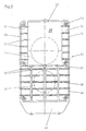
- the outer wall box shown comprises a wall box 8 inserted into a wall opening 4 of a room wall 3, which consists of a peripheral wall 12 and a box bottom 9.
- An intermediate wall 13 divides this wall box into an upper exhaust gas chamber 5 and a lower combustion air chamber 6.
- the exhaust and combustion air connection openings 10 and 11 are provided.
- the wall box is closed by a base plate 14 which is attached to the wall of the room.
- an outlet opening 15 for the exhaust gases is formed in this base plate.
- a nozzle rim 16 of a few, for example five to ten millimeters in height, surrounds this outlet opening.
- In the area of the combustion air chamber 6 there is an inlet opening 20 which is also provided with a nozzle edge 21.
- the exhaust gas outlet opening 15 is markedly larger than the combustion air inlet opening 20.
- a diameter ratio of 1.09 to 1.4 to 1 has been found to be advantageous.
- the enlarged outlet opening 15 not only enables easier exhaust gas discharge due to its large passage area, but also contributes to external wind influences on the outlet opening to prevent backflow in the exhaust gas duct due to greater possibilities for the exhaust gas flow to escape.
- Holes 23 are used to fasten the base plate to the wall of the room.
- a box cover 25 can be placed on the base plate and inserted via the eyelets 45 aligned with holes 23 by fastening screws (not shown).
- the box cover is surrounded by a deflector frame 26, which is formed by an upper frame wall 27, the side walls 28 and a partition wall 29.
- the side walls 28 have a sloping edge 30 sloping in the direction of the partition wall.
- the beveling of the side walls expediently begins only after a corner projection 31.
- the beveling of the side walls is between 3 ° and 6 °, advantageously 4 °, compared to the base plate.
- the partition wall 29 connecting the lower ends of the tapered side walls is therefore noticeably lower than the upper frame wall 27 and separates the exhaust gas area from the combustion air area outside the base plate.
- a narrow gap 32 in this partition serves to equalize the pressure between these two areas.
- a cover plate 33 is provided which completely covers the outlet opening and which merges into the upper frame wall 27 at the top and into the partition wall 29 below. In this way, the cover plate also takes an inclined position. As a result, a negative pressure is generated by a gust of wind, regardless of the wind direction, in the exhaust gas outlet area between the cover plate 33 and the side walls 28 to the outlet opening 15, so that the flow through the connected device is additionally supported. It has proven to be expedient here if the cover plate lifts out in the direction of the upper frame wall 27 slightly above the connecting plane through the inclined edges 30.
- the base plate is spanned in the area of the combustion air inlet by a grille protective basket 39, which is connected to the partition by struts 38 stands and rests on the base plate by means of a web frame 40.
- a cover housing 42 for a condensate drain pipe (not visible).
- the box cover 25 designed as a molded part expediently also has a circumferential fold 44 through which the box cover can be placed on the base plate in a secured and fixed arrangement.
Landscapes
- Engineering & Computer Science (AREA)
- Chemical & Material Sciences (AREA)
- Combustion & Propulsion (AREA)
- Mechanical Engineering (AREA)
- General Engineering & Computer Science (AREA)
- Housings, Intake/Discharge, And Installation Of Fluid Heaters (AREA)
Applications Claiming Priority (2)
| Application Number | Priority Date | Filing Date | Title |
|---|---|---|---|
| DE4129267 | 1991-09-03 | ||
| DE19914129267 DE4129267C1 (enExample) | 1991-09-03 | 1991-09-03 |
Publications (3)
| Publication Number | Publication Date |
|---|---|
| EP0530587A2 EP0530587A2 (de) | 1993-03-10 |
| EP0530587A3 EP0530587A3 (en) | 1993-05-19 |
| EP0530587B1 true EP0530587B1 (de) | 1995-07-26 |
Family
ID=6439761
Family Applications (1)
| Application Number | Title | Priority Date | Filing Date |
|---|---|---|---|
| EP19920114082 Expired - Lifetime EP0530587B1 (de) | 1991-09-03 | 1992-08-18 | Aussenwandkasten für einen Verbrennungsluft- und Abgaskanal eines mit einem Brennersystem arbeitenden Gerätes |
Country Status (2)
| Country | Link |
|---|---|
| EP (1) | EP0530587B1 (enExample) |
| DE (1) | DE4129267C1 (enExample) |
Family Cites Families (3)
| Publication number | Priority date | Publication date | Assignee | Title |
|---|---|---|---|---|
| DE1790155U (de) * | 1957-11-02 | 1959-06-11 | Otto Von Dr Blanquet | Stroemungssicherung fuer gasbeheizte aussenwandgeraete. |
| DE3025441C2 (de) * | 1980-07-04 | 1983-05-11 | Philipp Kreis GmbH & Co Truma-Gerätebau, 8000 München | Außenwandkasten für den Verbrennungsluft- und Abgaskanal eines mit einem Brennersystem arbeitenden Gerätes |
| GB2197940A (en) * | 1986-11-19 | 1988-06-02 | Baxi Partnership Ltd | Flue arrangement |
-
1991
- 1991-09-03 DE DE19914129267 patent/DE4129267C1/de not_active Expired - Lifetime
-
1992
- 1992-08-18 EP EP19920114082 patent/EP0530587B1/de not_active Expired - Lifetime
Also Published As
| Publication number | Publication date |
|---|---|
| EP0530587A3 (en) | 1993-05-19 |
| EP0530587A2 (de) | 1993-03-10 |
| DE4129267C1 (enExample) | 1993-01-14 |
Similar Documents
| Publication | Publication Date | Title |
|---|---|---|
| EP2247853B1 (de) | Windenergieanlageturm oder ein segment des windenergieanlageturms mit einer tür umfassend eine türzarge | |
| DE69702971T2 (de) | Vorrichtung zum abführen des regenwassers von dächern | |
| DE102010001319A1 (de) | Luftdurchlass mit einem Gehäuse sowie ein Deckensegel mit Luftdurchlass | |
| EP3232127B1 (de) | Dunstabzugshaube mit auslassgitter | |
| EP1559467B1 (de) | Schutzsieb zum Abschirmen eines Saugraums | |
| EP0530587B1 (de) | Aussenwandkasten für einen Verbrennungsluft- und Abgaskanal eines mit einem Brennersystem arbeitenden Gerätes | |
| DE3012588C2 (de) | Strahlungsbrenner, insbesondere für gasförmigen Brennstoff | |
| EP1839766B1 (de) | Abzug mit vorderer Abluftöffnung | |
| DE3025441C2 (de) | Außenwandkasten für den Verbrennungsluft- und Abgaskanal eines mit einem Brennersystem arbeitenden Gerätes | |
| DE69908009T2 (de) | Vorrichtung zum gleichmässigen Verdünnen von Abgas von einem Militärfahrzeug | |
| EP0864345A1 (de) | Tropfenabscheider | |
| EP3124869B1 (de) | Luftauslassgitter, insbesondere für einen ofen | |
| EP0950435B1 (de) | Spritzwandmodul und aus Spritzwandmodulen aufgebaute Spritzwand | |
| DE4419604A1 (de) | Schornsteinanordnung mit Regenauffänger | |
| EP0021281B1 (de) | Kaminkopf für Luft-Abgas-Kamine | |
| EP0122413B1 (de) | Kaminhaube | |
| DE1953889B2 (de) | Windschutzhaube für einen Außenwandheizofen | |
| AT207088B (de) | Abschirmung von Raumöffnungen durch einen Luftschleier | |
| DE3035575C2 (de) | Kühlvorrichtung zum Rückkühlen von Wasser im Gegenstrom | |
| EP0143914A2 (de) | Aussenwandkasten für den Verbrennungsluft- und Abgaskanal eines mit einem Brennersystem arbeitenden Gerätes | |
| DE85126C (enExample) | ||
| DE3323319C2 (enExample) | ||
| EP1058065B1 (de) | Schleuse für Reinraum-Anlagen | |
| DE812823C (de) | Heizofen mit geschlossenem Gehaeuse | |
| DE7343064U (de) | Vorrichtung zur Ableitung gasförmiger Medien aus Schaltanlagen |
Legal Events
| Date | Code | Title | Description |
|---|---|---|---|
| PUAI | Public reference made under article 153(3) epc to a published international application that has entered the european phase |
Free format text: ORIGINAL CODE: 0009012 |
|
| AK | Designated contracting states |
Kind code of ref document: A2 Designated state(s): FR GB IT SE |
|
| PUAL | Search report despatched |
Free format text: ORIGINAL CODE: 0009013 |
|
| AK | Designated contracting states |
Kind code of ref document: A3 Designated state(s): FR GB IT SE |
|
| 17P | Request for examination filed |
Effective date: 19931119 |
|
| 17Q | First examination report despatched |
Effective date: 19940912 |
|
| GRAA | (expected) grant |
Free format text: ORIGINAL CODE: 0009210 |
|
| ITF | It: translation for a ep patent filed | ||
| AK | Designated contracting states |
Kind code of ref document: B1 Designated state(s): FR GB IT SE |
|
| GBT | Gb: translation of ep patent filed (gb section 77(6)(a)/1977) |
Effective date: 19950807 |
|
| ET | Fr: translation filed | ||
| PLBE | No opposition filed within time limit |
Free format text: ORIGINAL CODE: 0009261 |
|
| 26N | No opposition filed | ||
| REG | Reference to a national code |
Ref country code: GB Ref legal event code: IF02 |
|
| PGFP | Annual fee paid to national office [announced via postgrant information from national office to epo] |
Ref country code: SE Payment date: 20070820 Year of fee payment: 16 |
|
| EUG | Se: european patent has lapsed | ||
| PG25 | Lapsed in a contracting state [announced via postgrant information from national office to epo] |
Ref country code: SE Free format text: LAPSE BECAUSE OF NON-PAYMENT OF DUE FEES Effective date: 20080819 |
|
| PGFP | Annual fee paid to national office [announced via postgrant information from national office to epo] |
Ref country code: GB Payment date: 20110802 Year of fee payment: 20 Ref country code: FR Payment date: 20110812 Year of fee payment: 20 |
|
| PGFP | Annual fee paid to national office [announced via postgrant information from national office to epo] |
Ref country code: IT Payment date: 20110819 Year of fee payment: 20 |
|
| REG | Reference to a national code |
Ref country code: GB Ref legal event code: PE20 Expiry date: 20120817 |
|
| PG25 | Lapsed in a contracting state [announced via postgrant information from national office to epo] |
Ref country code: GB Free format text: LAPSE BECAUSE OF EXPIRATION OF PROTECTION Effective date: 20120817 |