EP0529214A2 - Continuous double band press - Google Patents
Continuous double band press Download PDFInfo
- Publication number
- EP0529214A2 EP0529214A2 EP92109516A EP92109516A EP0529214A2 EP 0529214 A2 EP0529214 A2 EP 0529214A2 EP 92109516 A EP92109516 A EP 92109516A EP 92109516 A EP92109516 A EP 92109516A EP 0529214 A2 EP0529214 A2 EP 0529214A2
- Authority
- EP
- European Patent Office
- Prior art keywords
- press
- plate
- shape
- pressure
- plates
- Prior art date
- Legal status (The legal status is an assumption and is not a legal conclusion. Google has not performed a legal analysis and makes no representation as to the accuracy of the status listed.)
- Granted
Links
Images


Classifications
-
- B—PERFORMING OPERATIONS; TRANSPORTING
- B27—WORKING OR PRESERVING WOOD OR SIMILAR MATERIAL; NAILING OR STAPLING MACHINES IN GENERAL
- B27N—MANUFACTURE BY DRY PROCESSES OF ARTICLES, WITH OR WITHOUT ORGANIC BINDING AGENTS, MADE FROM PARTICLES OR FIBRES CONSISTING OF WOOD OR OTHER LIGNOCELLULOSIC OR LIKE ORGANIC MATERIAL
- B27N3/00—Manufacture of substantially flat articles, e.g. boards, from particles or fibres
- B27N3/08—Moulding or pressing
- B27N3/24—Moulding or pressing characterised by using continuously acting presses having endless belts or chains moved within the compression zone
-
- B—PERFORMING OPERATIONS; TRANSPORTING
- B30—PRESSES
- B30B—PRESSES IN GENERAL
- B30B15/00—Details of, or accessories for, presses; Auxiliary measures in connection with pressing
- B30B15/06—Platens or press rams
- B30B15/061—Cushion plates
-
- B—PERFORMING OPERATIONS; TRANSPORTING
- B30—PRESSES
- B30B—PRESSES IN GENERAL
- B30B5/00—Presses characterised by the use of pressing means other than those mentioned in the preceding groups
- B30B5/04—Presses characterised by the use of pressing means other than those mentioned in the preceding groups wherein the pressing means is in the form of an endless band
- B30B5/06—Presses characterised by the use of pressing means other than those mentioned in the preceding groups wherein the pressing means is in the form of an endless band co-operating with another endless band
-
- B—PERFORMING OPERATIONS; TRANSPORTING
- B30—PRESSES
- B30B—PRESSES IN GENERAL
- B30B7/00—Presses characterised by a particular arrangement of the pressing members
- B30B7/02—Presses characterised by a particular arrangement of the pressing members having several platens arranged one above the other
-
- Y—GENERAL TAGGING OF NEW TECHNOLOGICAL DEVELOPMENTS; GENERAL TAGGING OF CROSS-SECTIONAL TECHNOLOGIES SPANNING OVER SEVERAL SECTIONS OF THE IPC; TECHNICAL SUBJECTS COVERED BY FORMER USPC CROSS-REFERENCE ART COLLECTIONS [XRACs] AND DIGESTS
- Y10—TECHNICAL SUBJECTS COVERED BY FORMER USPC
- Y10T—TECHNICAL SUBJECTS COVERED BY FORMER US CLASSIFICATION
- Y10T156/00—Adhesive bonding and miscellaneous chemical manufacture
- Y10T156/17—Surface bonding means and/or assemblymeans with work feeding or handling means
- Y10T156/1702—For plural parts or plural areas of single part
- Y10T156/1712—Indefinite or running length work
- Y10T156/1741—Progressive continuous bonding press [e.g., roll couples]
Definitions
- the invention relates to a shape compensation plate according to the preamble of claim 1 or a continuously operating double belt press for the production of endless material webs such as laminates, chipboard or fiberboard, plywood or the like according to the preamble of claim 18 or a discontinuously working single or multi-day press for production of section-shaped materials according to the preamble of claim 24.
- Double belt presses are used for the continuous production of endless web-shaped materials, in particular for the production of decorative laminate laminates, copper-clad electrical laminates, thermoplastic webs, chipboard, fiberboard and the like.
- These double belt presses have two endless rotating press belts, between which the material web is cured under the action of pressure and possibly also heat while being transported in the forward direction.
- pressure plates are arranged in the press frame of the double belt press, from which the pressure is transmitted to the inside of the press belts and from these to the material web.
- ring-shaped, self-contained sliding surface seals are arranged along the edge region of the pressure plate, which are applied to the press belt with one surface such that the press belt slides along this surface during operation of the double belt press.
- This creates pressure chambers that are delimited in the vertical direction by the pressure plate and the inside of the press belt and in the horizontal direction by the sliding surface seals.
- a fluid pressure medium for example oil or compressed air, is introduced into these pressure plates.
- Such isobaric double belt presses are known for example from DE-PS 27 22 197.
- the pressure is mechanically transferred from the pressure plate to the inside of the press belt via rollers.
- a fixed roller bed arranged in the pressure plate is known from DE-OS 31 23 291.
- the roller bed consists of rollers arranged offset from one another, which are mounted in bearing blocks by means of shafts, these bearing strips in turn being fastened in the pressure plate.
- a double belt press which combines the isobaric and the isochoric principle.
- the roller bed is arranged in a pressure pad which is sealed on the side by sliding surface seals.
- This double belt press can be operated purely isochorously, in that only the roller bed is placed against the press belt, without a pressurized fluid pressure medium being introduced into the pressure pad.
- a purely isobaric mode of operation is also possible in that the roller bed is not placed against the press belt, but only a fluid pressure medium maintains the pressure in the pressure pad.
- isobar / isochor both the roller bed is placed against the press belt and a pressurized fluid pressure medium is introduced into the pressure pad.
- a further pressure chamber is used to exert pressure on the roller bed.
- This is arranged on the side of the pressure plate facing away from the press belt and is delimited in the vertical direction by the pressure plate and a closure located in the press frame, and in the horizontal direction by side seals which are designed in the same way as the sliding surface seals for the pressure pad.
- a disadvantage of this known design of a double belt press that can be operated isobarically / isochorously is that leakage of fluid pressure medium can occur on the side seals of the pressure chamber arranged on the side of the pressure plate facing away from the press belt, in particular at higher pressures, and can contaminate the press frame and the material to be pressed .
- the material to be pressed often requires treatment during the pressing at elevated temperature. To do this, the printing plate is heated to the required temperature.
- the known sealing materials for the side seals consist of plastic or elastomers, which are only resistant up to temperatures of approx. 270 0C. At higher temperatures, the side seals of this pressure chamber are therefore destroyed, which ultimately leads to the failure of the pressurization by the pressure chamber and thus to a time-consuming and costly repair of the double belt press. This double belt press is therefore not suitable for use at higher temperatures.
- the invention is based, to develop the isochoric or combined isochoric / isobar double belt press so that it can be used reliably at elevated temperatures.
- the advantages that can be achieved with the invention are, in particular, that no leakage of pressure medium can occur in the shape-compensating plate according to the invention due to the hermetic lateral edge seal. Contamination of the press and the material to be pressed is therefore excluded with certainty.
- the shape compensation plate contains no plastics, so that the double belt press can also be used for high temperatures. With the help of the shape compensation plate, deflections in the pressing area of the double belt press, in particular the press frame, are compensated, as a result of which a better dimensionally stable product is produced on the double belt press.
- the shape-adjustment plate contains a metallic liquid as the fluid pressure medium.
- Metallic liquids have a very good thermal conductivity, so that unhindered heat transfer between the press belts and a heat exchange plate located plane-parallel in the press frame is guaranteed. This leads to a qualitatively improved pressed product and allows the double belt press to be operated at higher speeds.
- the shape compensation plate is divided into a plurality of individual strip-shaped shape adjustment plates lying next to one another. This gives you the opportunity to process pressed material with different widths in the double belt press.
- the shape-compensating plate according to the invention can be used successfully not only in continuously operating double belt presses but also in discontinuously operating single or multi-day presses. Such a single or multi-day press is described by the technical teaching contained in the characterizing part of patent claim 7.
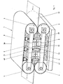
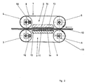
- the continuously operating double belt press 1 shown in FIGS. 1 and 2 consists of an upper press belt unit 2 and a lower press belt unit 3, which are arranged one above the other.
- the press belt units 2, 3 in turn consist of two each, in bearing bridges 38, 39 rotatably mounted deflection drums 4, 5 or 6, 7 and an endless press belt 8, 9 together.
- the press belt 8, 9, which usually consists of a high-tensile steel band, is guided around the deflection drums 4, 5 or 6, 7 and tensioned by means of hydraulic cylinders 10 arranged in the bearing bridges 38, 39.
- At least one deflection drum of each press belt unit 2, 3 is driven by a motor, so that the two press belts 8, 9 move according to the arrows in the deflection drums 5, 6.
- the bearing bridges 38, 39 are fastened to the press frame 40, 41, which is schematically indicated in FIG. 1.
- the press frame 40, 41 is not shown in Figure 2 for reasons of clarity.
- the detailed design of the press frame can be found, for example, in DE-OS 32 34 082.
- reaction zone 11 Between the lower belt run of the upper press belt 8 and the upper belt run of the lower press belt 9 lies the reaction zone 11, in which the material web 12 leading from right to left in the drawings is pressed under surface pressure during the passage through the double belt press 1.
- pressure plates 13 are arranged in the press frame 40, 41 of the double belt press 1, of which the surface pressure is mechanically applied to the inside of the press belts 8, 9 and then transferred by them to the material web 12 , which is an isochoric double belt press.
- a roller bed consisting of stationary rollers 14 is used to generate the mechanical surface pressure between the pressure plate 13 and the inside of the press belt 8, 9.
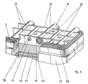
- roller bed used for the mechanical pressure transmission can be seen in more detail in FIG. 3 in a perspective view.
- 13 support bearing strips 16 are arranged in the pressure plate.
- support bearing strips 16 there are support shafts 17 on which the rollers 14 are arranged in rows parallel to the feed direction of the press belts 8, 9.
- the rollers 14 have a smaller length than the width of the pressure plate 13, so that a plurality of rollers 14 are arranged side by side on a support shaft 17.
- the rollers 14 are in two adjacent rows half a roller width offset from each other by replacing every second support bearing bore 18 with an opening 19 which is slightly larger than the diameter of the roller 14.
- the roller bed can additionally be surrounded by one or more sliding surface seals 20, which are arranged in the pressure plate 13 and are applied to the pressing belt 8, 9 with one surface, so that the pressing belt 8, 9 slides along these sliding surface seals 20.
- the sliding surface seal 20 is closed in a ring shape, so that the roller bed lies in an enclosed space and can be filled with lubricant for the rollers.
- the cavity between two rollers 14 can also be provided with a filler 15 in order to improve the lubrication by forming capillary gaps between the roller 14, the support bearing strips 16 and the pressure plate 13.
- the space enclosed by the sliding surface seal 20 can also be provided with a fluid pressure medium, which additionally exerts a hydraulic pressure on the inside of the press belts 8, 9. Such a configuration is then a double belt press working in a combined isobar / isochoric manner.
- the pressure plate 13 consists of a carrier plate 42 in which the support bearing strips 16 for the roller bed are fastened, an adjoining shape compensation plate 21 and a rigid heat exchange plate 43.
- the carrier plate 42 is preferably of flexible design.
- the heat exchange plate 43 there are bores 44 through which a fluid heat transfer medium can flow. As a result, the heat exchange plate 43 can be heated or cooled, so that heat can be supplied to or removed from the material web 12 via the shape-compensating plate 21, the carrier plate 42 and the press belt 8, 9.
- the heat exchange plate 43 can be dispensed with and the shape-compensating plate 21 directly on the press frame 40, 41 may be arranged.
- Such a heat exchange can be achieved, for example, by supplying or removing the heated or cooled pressure medium located in the space between the sliding surface seals 20, so that heat is exchanged between the press belt 8, 9 and the pressure medium by convection due to the flow can.
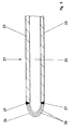
- the shape compensation plate 21 according to the invention which is arranged on the rear side of the carrier plate 42, that is to say on the side of the roller bed facing away from the press belt 8, 9, is composed of two plates arranged parallel to one another and at a certain distance from one another, namely a base plate 22 and a cover plate 23 , as can be seen in Figure 5.
- the base and cover plate 22, 23 consist of metal, for example steel.
- An elastic bellows 24 runs along the edge of the base plate 22 and cover plate 23 and is attached at one end to the base plate 22 and at the other end to the cover plate 23.
- a chamber 25 is formed between the base plate 22 and the cover plate 23, which is hermetically sealed laterally with the elastic bellows 24.
- this chamber 25 which is sealed off from the outside, there is a fluid under pressure as the pressure medium.
- This fluid can be a liquid under pressure, for example oil.
- a gas under pressure into this chamber 25.
- a metallic liquid such as mercury or wood metal, is particularly preferred.
- Wood metal is a low-melting alloy of bismuth, lead, tin and cadmium. If the material web 12 to be pressed is simultaneously heated in the double belt press 1 under the action of pressure, it is also possible to choose an alloy or a metal as the content for the chamber 25 which is molten at the temperature to be applied to which the heat exchange plate 43 is heated for example tin. Due to the hermetic seal by the elastic bellows 24, leakage of the fluid pressure medium from the shape-compensating plate 21 is avoided with certainty.
- the elastic bellows 24, which laterally surrounds the chamber 25, has an approximately semicircular cross section. It is composed of individual, superimposed, rectangular metal foils or sheets 26, the individual layers of the metal foils or sheets 26 being welded into rings. For example, a high tensile spring steel or stainless steel is suitable as material for these sheets.
- This sheet metal ring package is then bent so that it has a semicircular to U-shaped cross section, as can be seen in FIG. 5, and is welded to one another at the edges. This structure gives the laminated core a high degree of elasticity.
- the laminated core is then placed at one end on the base plate 22 and at the other end on the cover plate 23, the laminated core at the corners of the plates 22, 23 being bent in a circle by approximately 90 ° to form a U-quarter curve. Finally, the ends of the laminated core lying against the plates 22, 23 are fastened to the plates 22, 23. This attachment can also be carried out by means of a weld seam.
- the individual metal foils or sheets 26 can also consist of electroformed parts, which are already galvanically deposited in the desired semicircular shape and then welded to one another at the edges 27. As a result, the step of bending the laminated core into a semicircular shape can be omitted.
- the surface pressure exerted by the pressure plate 13 fastened in the press frame 40, 41 acts on the material web 12 via the roller bed and the press belts 8, 9.
- an additional hydraulic pressure acts on the material web 12 from the fluid pressure medium located in the space between the sliding surface seals 20. Due to the applied pressing pressure, reaction forces emanate from the material web 12, which are introduced into the pressure plate 13 via the roller bed and absorbed by the press frame 40, 41 in which the pressure plate 13 is fastened.
- the pressure plate 13 consists of a carrier plate 42 and the shape-compensating plate 21. If bends occur in the roller bed or in the press frame 40, 41, these bends are counteracted by the isobaric pressure behavior of the fluid pressure medium located in the chamber 25 of the shape-adjustment plate 21. This counteraction is supported by the flexibility of the support plate 42.
- the shape compensation plate 21 consists of metallic materials. These are stable even at elevated temperatures. Thus, the double belt press 1 equipped with the shape compensation plate 21 according to the invention can be used reliably even at elevated temperatures.
- a support plate 28 can be arranged in the chamber 25 to support it.
- the support plate 28 is arranged essentially parallel to the base plate 22 and cover plate 23.
- the edge region 29 of the support plate 28 is slightly chamfered.
- the beveled edge region 29 is arranged in the inner curvature of the bellows 24, so that the bellows 24 is supported on the side facing the chamber 25 by the beveled edge region 29.
- Particularly high reaction forces acting on the elastic bellows 24 are then absorbed by the support plate 28.
- This support plate 28 can consist of copper, so that good thermal conductivity is also ensured in the chamber 25. This can be necessary in particular if a metal is selected as the fluid pressure medium in the chamber 25, which becomes molten at the operating temperature of the double belt press 1 or if particularly large amounts of heat between the heat exchange plate 43 and the Press belt 8, 9 to be transferred. If it is desired to increase the elasticity of the chamfered edge region 29 of the support plate 28, incisions 45 can be made in the chamfered edge region 29.
- a further embodiment for the shape-compensating plate 21 can be seen in FIG.
- a bore 30 is made in the upper cover plate 23.
- the fluid pressure medium can be fed into the chamber 25 through this bore 30, so that the pressure in the chamber 25 can advantageously be varied.
- the shape compensation plate 21 only needs to be filled with the fluid pressure medium when it is actually needed. With such an embodiment, a form compensation plate 21 that can be switched on and off can thus be realized.
- the shape compensation plates 21 With the shape compensation plates 21 according to the invention, multi-format double belt presses can also be realized. Since the pressurized press belts 8, 9 are supported in the reaction zone 11 against the material web 12, this extends over the entire width of the reaction zone 11 in conventional double belt presses. In order to be able to use narrower material webs 12 as well, the shape-compensating plate can be used in several transverse, strips extending in the longitudinal direction can be divided, each strip being designed as a separate, self-contained shape-compensating plate. If desired, each strip-shaped shape compensation plate can also be designed so that it can be switched on and off separately.
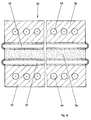
- Such a strip-shaped arrangement of a plurality of shape compensation plates 31, 32 can be seen in FIG. 7, in which the pressure plate 13 with a roller bed is shown in a top view, the carrier plate 42 being partially omitted in order to show the shape compensation plates 31, 32 located underneath.
- These strip-shaped shape compensation plates 31, 32 are arranged with the desired width and in the desired number in the pressure plate 13. The width of the material web 12 is then selected so that it is just covered by one or more shape-compensating plates 31, 32. This causes deflections at precisely the points in the roller bed compensates where the material web is pressurized, so that ultimately a material web 12 lying within the thickness tolerances is again generated.
- the shape compensation plate according to the invention can be used not only in a continuously operating double belt press, but also in a discontinuously operating deck press 33, as is shown schematically in FIG.
- the pressed material 36 is compressed between two press plates 34 and 35.
- the pressure plates 34, 35 have bores 46 through which a heat transfer medium can be passed so that they can be heated or cooled.
- discrepancies and thickness tolerances in the pressed material 36 and the pressing plates 34, 35, as well as deformations of the press yoke and press table caused by load absorption can cause local pressure differences and cause the pressing plates 34, 35 to warp, which ultimately leads to differences in thickness in the pressing material 36 and thus to rejects leads.
- Such warping of the pressure plates 34, 35 is avoided according to the invention in that the shape compensation plate 37 according to the invention is fastened to the pressure plates 34, 35 on the side facing the material 36 to be pressed.
- a carrier plate can be dispensed with, that is to say the shape-compensating plate 37 can rest directly on the material 36 to be pressed.
- the shape compensation plate 37 is designed in accordance with the above exemplary embodiments and absorbs local pressure differences from the pressed material 36, as a result of which warping or warping of the pressed plates 34, 35 is avoided, so that a pressed material 36 lying within the desired thickness tolerances is produced.
- the shape compensation plate 37 according to the invention can be used not only in single-day presses, but also in multi-day presses. This is done in the same way as for the single-day presses, that is, they are arranged between the material to be pressed and the press plate.
- an attachment of the shape compensation plate 37 to the pressure plates 34, 35 is not absolutely necessary, it is sufficient if the shape compensation plates 37 between the pressure plate 34, 35 and the material to be pressed 36 into the Press 33 can be inserted.
- the shape-compensating plates 37 according to the invention in the case of single- or multi-day presses, the previously customary press pads, which were destroyed after a few press cycles at the latest and therefore had to be discarded, can be replaced by the permanent shape-compensating plate 37.
Abstract
Description
Die Erfindung betrifft eine Formausgleichsplatte gemäß dem Oberbegriff des Anspruchs 1 bzw. eine kontinuierlich arbeitende Doppelbandpresse zur Herstellung von endlosen Materialbahnen wie Laminaten, Span- oder Faserplatten, Sperrholz oder dergleichen gemäß dem Oberbegriff des Patentanspruchs 18 bzw. eine diskontinuierlich arbeitende Ein- oder Mehretagenpresse zur Herstellung von abschnittsförmigen Materialien gemäß dem Oberbegriff des Patentanspruchs 24.The invention relates to a shape compensation plate according to the preamble of claim 1 or a continuously operating double belt press for the production of endless material webs such as laminates, chipboard or fiberboard, plywood or the like according to the preamble of
Doppelbandpressen (siehe auch DE-OS 24 21 296) dienen zur kontinuierlichen Herstellung endloser bahnförmiger Werkstoffe, insbesondere zur Herstellung von dekorativen Schichtstofflaminaten, kupferkaschierten Elektrolaminaten, Thermoplastbahnen, Spanplatten, Faserplatten und dergleichen. Diese Doppelbandpressen besitzen zwei endlos umlaufende Preßbänder, zwischen denen die Werkstoffbahn unter Einwirkung von Druck und gegebenenfalls auch Wärme bei gleichzeitigem Transport in Vorlaufrichtung ausgehärtet wird. Zur Erzeugung des Flächendrucks sind im Pressengestell der Doppelbandpresse Druckplatten angeordnet, von denen der Druck auf die Innenseiten der Preßbänder und von diesen auf die Werkstoffbahn übertragen wird.Double belt presses (see also DE-OS 24 21 296) are used for the continuous production of endless web-shaped materials, in particular for the production of decorative laminate laminates, copper-clad electrical laminates, thermoplastic webs, chipboard, fiberboard and the like. These double belt presses have two endless rotating press belts, between which the material web is cured under the action of pressure and possibly also heat while being transported in the forward direction. To generate the surface pressure, pressure plates are arranged in the press frame of the double belt press, from which the pressure is transmitted to the inside of the press belts and from these to the material web.
Zur Übertragung des Druckes von der Druckplatte auf die Preßbandinnenseite gibt es im wesentlichen zwei unterschiedliche Wirkprinzipien.There are essentially two different operating principles for transferring the pressure from the pressure plate to the inside of the press belt.
Bei den sogenannten isobaren Maschinen dieser Gattung werden entlang des Randbereichs der Druckplatte ringförmig in sich geschlossene Gleitflächendichtungen angeordnet, die mit einer Fläche so an das Preßband angelegt werden, daß das Preßband an dieser Fläche im Betrieb der Doppelbandpresse entlanggleitet. Dadurch entstehen Druckkammern, die in vertikaler Richtung von der Druckplatte und der Preßbandinnenseite und in horizontaler Richtung von den Gleitflächendichtungen begrenzt werden. In diese Druckplatten wird ein fluides Druckmittel, zum Beispiel Öl oder Druckluft, eingebracht. Solche isobare Doppelbandpressen sind beispielsweise aus der DE-PS 27 22 197 bekannt.In the so-called isobaric machines of this type, ring-shaped, self-contained sliding surface seals are arranged along the edge region of the pressure plate, which are applied to the press belt with one surface such that the press belt slides along this surface during operation of the double belt press. This creates pressure chambers that are delimited in the vertical direction by the pressure plate and the inside of the press belt and in the horizontal direction by the sliding surface seals. A fluid pressure medium, for example oil or compressed air, is introduced into these pressure plates. Such isobaric double belt presses are known for example from DE-PS 27 22 197.
Bei den isochoren Maschinen dieser Gattung wird der Druck mechanisch über Rollen von der Druckplatte auf die Preßbandinnenseite übertragen. Ein in der Druckplatte angeordnetes, ortsfestes Rollenbett ist aus der DE-OS 31 23 291 bekannt. Das Rollenbett besteht aus versetzt zueinander angeordneten Rollen, die mittels Wellen in Lagerleisten gelagert sind, wobei diese Lagerleisten wiederum in der Druckplatte befestigt sind.In the isochoric machines of this type, the pressure is mechanically transferred from the pressure plate to the inside of the press belt via rollers. A fixed roller bed arranged in the pressure plate is known from DE-OS 31 23 291. The roller bed consists of rollers arranged offset from one another, which are mounted in bearing blocks by means of shafts, these bearing strips in turn being fastened in the pressure plate.
Aus der DE-OS 33 04 754 schließlich ist eine Doppelbandpresse bekannt geworden, die das isobare und das isochore Prinzip kombiniert. Dazu ist das Rollenbett in einem Druckkissen angeordnet, das seitlich von Gleitflächendichtungen abgedichtet ist. Diese Doppelbandpresse kann rein isochor betrieben werden, indem nur das Rollenbett gegen das Preßband angestellt wird, ohne daß ein unter Druck stehendes fluides Druckmittel in das Druckkissen eingebracht wird. Auch eine rein isobare Betriebsweise ist möglich, indem das Rollenbett nicht gegen das Preßband angestellt wird, sondern nur ein fluides Druckmittel den Druck im Druckkissen aufrecht erhält. Bei der gemischten Betriebsweise isobar/isochor wird sowohl das Rollenbett gegen das Preßband angestellt als auch ein unter Druck stehendes fluides Druckmittel in das Druckkissen eingebracht. In der gezeigten Doppelbandpresse wird zur Ausübung eines Druckes auf das Rollenbett eine weitere Druckkammer verwendet. Diese ist an der dem Preßband abgewandten Seite der Druckplatte angeordnet und wird in vertikaler Richtung von der Druckplatte und einen im Pressengestell befindlichen Abschluß sowie in horizontaler Richtung von seitlichen Dichtungen begrenzt, die gleich wie die Gleitflächendichtungen für das Druckkissen ausgebildet sind. Durch Einbringen eines fluiden Druckmittels in diese Druckkammer wird die Druckplatte und damit das in der Druckplatte befindliche Rollenbett gegen das Preßband angestellt.Finally, from DE-OS 33 04 754 a double belt press has become known which combines the isobaric and the isochoric principle. For this purpose, the roller bed is arranged in a pressure pad which is sealed on the side by sliding surface seals. This double belt press can be operated purely isochorously, in that only the roller bed is placed against the press belt, without a pressurized fluid pressure medium being introduced into the pressure pad. A purely isobaric mode of operation is also possible in that the roller bed is not placed against the press belt, but only a fluid pressure medium maintains the pressure in the pressure pad. In the mixed mode of operation isobar / isochor, both the roller bed is placed against the press belt and a pressurized fluid pressure medium is introduced into the pressure pad. In the double belt press shown, a further pressure chamber is used to exert pressure on the roller bed. This is arranged on the side of the pressure plate facing away from the press belt and is delimited in the vertical direction by the pressure plate and a closure located in the press frame, and in the horizontal direction by side seals which are designed in the same way as the sliding surface seals for the pressure pad. By introducing a fluid pressure medium into this pressure chamber, the pressure plate and thus the roller bed located in the pressure plate are placed against the press belt.
Nachteilig bei dieser bekannten Ausbildung einer kombiniert isobar/isochor betreibbaren Doppelbandpresse ist, daß an den seitlichen Dichtungen der an der dem Preßband abgewandten Seite der Druckplatte angeordneten Druckkammer, insbesondere bei höheren Drücken, Leckage von fluidem Druckmittel auftreten kann und das Pressengestell sowie das Preßgut verschmutzen kann. Häufig erfordert das Preßgut eine Behandlung während der Verpressung bei erhöhter Temperatur. Dazu wird die Druckplatte auf die benötigte Temperatur erwärmt.A disadvantage of this known design of a double belt press that can be operated isobarically / isochorously is that leakage of fluid pressure medium can occur on the side seals of the pressure chamber arranged on the side of the pressure plate facing away from the press belt, in particular at higher pressures, and can contaminate the press frame and the material to be pressed . The material to be pressed often requires treatment during the pressing at elevated temperature. To do this, the printing plate is heated to the required temperature.
Die bekannten Dichtungswerkstoffe für die seitlichen Dichtungen bestehen aus Kunststoff oder Elastomeren, die lediglich bis zu Temperaturen von ca. 270 ⁰C beständig sind. Bei höheren Temperaturen werden daher die seitlichen Dichtungen dieser Druckkammer zerstört, was letztendlich zum Ausfall der Druckbeaufschlagung durch die Druckkammer und dadurch zu einer zeit- und kostenaufwendigen Reparatur der Doppelbandpresse führt. Zum Einsatz bei höheren Temperaturen ist diese Doppelbandpresse daher nicht geeignet.The known sealing materials for the side seals consist of plastic or elastomers, which are only resistant up to temperatures of approx. 270 ⁰C. At higher temperatures, the side seals of this pressure chamber are therefore destroyed, which ultimately leads to the failure of the pressurization by the pressure chamber and thus to a time-consuming and costly repair of the double belt press. This double belt press is therefore not suitable for use at higher temperatures.
Der Erfindung liegt die Aufgabe zugrunde, die isochor oder kombiniert isochor/isobar betreibbare Doppelbandpresse so weiterzuentwickeln, daß sie betriebssicher bei erhöhten Temperaturen einsetzbar ist.The invention is based, to develop the isochoric or combined isochoric / isobar double belt press so that it can be used reliably at elevated temperatures.
Die Lösung dieser Aufgabe wird durch die im Kennzeichen des Patentanspruchs 1 beschriebene technische Lehre vermittelt.This object is achieved by the technical teaching described in the characterizing part of patent claim 1.
Die mit der Erfindung erzielbaren Vorteile bestehen insbesondere darin, daß bei der erfindungsgemäßen Formausgleichsplatte aufgrund der hermetischen seitlichen Randabdichtung keinerlei Leckage von Druckmittel auftreten kann. Ein Verschmutzen der Presse und des Preßgutes ist daher mit Sicherheit ausgeschlossen. Dadurch entsteht beim Betrieb der Doppelbandpresse mit der erfindungsgemäßen Formausgleichsplatte weitaus weniger Abfall an Preßgut als bei bisherigen Doppelbandpressen. Die Formausgleichsplatte enthält keine Kunststoffe, so daß die Doppelbandpresse auch für hohe Temperaturen einsetzbar ist. Mit Hilfe der Formausgleichsplatte werden Durchbiegungen im Preßbereich der Doppelbandpresse, insbesondere des Pressengestells, kompensiert, wodurch ein besser maßhaltiges Produkt auf der Doppelbandpresse hergestellt wird.The advantages that can be achieved with the invention are, in particular, that no leakage of pressure medium can occur in the shape-compensating plate according to the invention due to the hermetic lateral edge seal. Contamination of the press and the material to be pressed is therefore excluded with certainty. This results in the operation of the double belt press with the shape compensation plate according to the invention, far less waste of pressed material than in previous double belt presses. The shape compensation plate contains no plastics, so that the double belt press can also be used for high temperatures. With the help of the shape compensation plate, deflections in the pressing area of the double belt press, in particular the press frame, are compensated, as a result of which a better dimensionally stable product is produced on the double belt press.
In einer vorteilhaften Ausgestaltung der Erfindung enthält die Formausgleichsplatte als fluides Druckmedium eine metallische Flüssigkeit. Metallische Flüssigkeiten besitzen eine sehr gute Wärmeleitfähigkeit, so daß eine ungehinderte Wärmeübertragung zwischen den Preßbändern und einer planparallel im Pressengestell befindlichen Wärmeaustauschplatte gewährleistet ist. Dies führt zu einem qualitativ verbesserten verpreßten Produkt und gestattet die Doppelbandpresse mit höheren Geschwindigkeiten zu betreiben.In an advantageous embodiment of the invention, the shape-adjustment plate contains a metallic liquid as the fluid pressure medium. Metallic liquids have a very good thermal conductivity, so that unhindered heat transfer between the press belts and a heat exchange plate located plane-parallel in the press frame is guaranteed. This leads to a qualitatively improved pressed product and allows the double belt press to be operated at higher speeds.
In einer weiteren vorteilhaften Ausgestaltung wird die Formausgleichsplatte in mehrere einzelne, nebeneinanderliegende streifenförmige Formausgleichsplatten aufgeteilt. Man erhält damit die Möglichkeit, Preßgut mit unterschiedlichen Breiten in der Doppelbandpresse zu verarbeiten.In a further advantageous embodiment, the shape compensation plate is divided into a plurality of individual strip-shaped shape adjustment plates lying next to one another. This gives you the opportunity to process pressed material with different widths in the double belt press.
Die erfindungsgemäße Formausgleichsplatte läßt sich nicht nur in kontinuierlich arbeitenden Doppelbandpressen sondern auch in diskontinuierlich arbeitenden Ein- oder Mehretagenpressen mit Erfolg einsetzen. Eine solche Ein- oder Mehretagenpresse wird durch die im Kennzeichen des Patentanspruchs 7 enthaltene technische Lehre beschrieben.The shape-compensating plate according to the invention can be used successfully not only in continuously operating double belt presses but also in discontinuously operating single or multi-day presses. Such a single or multi-day press is described by the technical teaching contained in the characterizing part of
Ein bevorzugtes Ausführungsbeispiel der Erfindung ist in den Zeichnungen dargestellt und wird im folgenden näher beschrieben. Es zeigen
- Figur 1
- schematisch eine Doppelbandpresse in Seitenansicht,
- Figur 2
- schematisch eine Doppelbandpresse im Längsschnitt,
Figur 3- ein Rollenbett in perspektivischer Ansicht,
Figur 4- einen Schnitt durch die Druckplatte in Längsrichtung,
Figur 5- einen Schnitt durch die Formausgleichsplatte,
Figur 6- einen Schnitt durch die Formausgleichsplatte in einer weiteren Ausführungsform,
Figur 7- eine streifenförmige Anordnung mehrerer Formausgleichsplatten und
Figur 8- schematisch eine Etagenpresse.
- Figure 1
- schematically a double belt press in side view,
- Figure 2
- schematically a double belt press in longitudinal section,
- Figure 3
- a roller bed in perspective view,
- Figure 4
- a section through the pressure plate in the longitudinal direction,
- Figure 5
- a section through the shape compensation plate,
- Figure 6
- 4 shows a section through the shape-compensating plate in a further embodiment,
- Figure 7
- a strip-shaped arrangement of several shape compensating plates and
- Figure 8
- schematically a stack press.
Die in Figur 1 und 2 dargestellte kontinuierlich arbeitende Doppelbandpresse 1 besteht aus einer oberen Preßbandeinheit 2 und einer unteren Preßbandeinheit 3, die übereinander angeordnet sind. Die Preßbandeinheiten 2, 3 setzen sich wiederum aus je zwei, in Lagerbrücken 38, 39 drehbar gelagerten Umlenktrommeln 4, 5 bzw. 6, 7 und je einem endlosen Preßband 8, 9 zusammen. Das gewöhnlicherweise aus einem hochzugfesten Stahlband bestehende Preßband 8, 9 ist um die Umlenktrommeln 4, 5 bzw. 6, 7 herumgeführt und mittels in den Lagerbrücken 38, 39 angeordneten Hydraulikzylindern 10 gespannt. Mindestens eine Umlenktrommel jeder Preßbandeinheit 2, 3 wird durch einen Motor angetrieben, so daß sich die beiden Preßbänder 8, 9 entsprechend den Pfeilen in den Umlenktrommeln 5, 6 bewegen. Die Lagerbrücken 38, 39 sind an dem in Figur 1 schematisch angedeuteten Pressengestell 40, 41 befestigt. Das Pressengestell 40, 41 ist in Figur 2 aus Übersichtlichkeitsgründen nicht eingezeichnet. Die nähere Ausbildung des Pressengestells kann beispielsweise der DE-OS 32 34 082 entnommen werden.The continuously operating double belt press 1 shown in FIGS. 1 and 2 consists of an upper press belt unit 2 and a lower
Zwischen dem unteren Bandtrum des oberen Preßbandes 8 und dem oberen Bandtrum des unteren Preßbandes 9 liegt die Reaktionszone 11, in der die in den Zeichnungen von rechts nach links vorlaufende Materialbahn 12 unter Flächendruck während des Durchlaufs durch die Doppelbandpresse 1 verpreßt wird. Zur Erzeugung des auf die Materialbahn 12 in der Reaktionszone 11 einwirkenden Flächendrucks sind im Pressengestell 40, 41 der Doppelbandpresse 1 Druckplatten 13 angeordnet, von denen der Flächendruck mechanisch auf die Innenseiten der Preßbänder 8, 9 aufgebracht und dann von diesen auf die Materialbahn 12 übertragen wird, womit es sich um eine isochore Doppelbandpresse handelt. Zur Erzeugung des mechanischen Flächendrucks zwischen der Druckplatte 13 und der Innenseite des Preßbandes 8, 9 dient ein aus ortsfesten Rollen 14 bestehendes Rollenbett.Between the lower belt run of the
Das zur mechanischen Druckübertragung benutzte Rollenbett ist in Figur 3 in perspektivischer Ansicht näher zu sehen. In Längsrichtung der Druckplatte 13, das heißt in Vorlaufrichtung des Preßbandes 8, 9 sind in der Druckplatte 13 Stützlagerleisten 16 angeordnet. In diesen Stützlagerleisten 16 befinden sich Stützwellen 17, auf denen die Rollen 14 in Reihen parallel zur Vorschubrichtung der Preßbänder 8, 9 angeordnet sind. Die Rollen 14 besitzen eine kleinere Länge als die Breite der Druckplatte 13, so daß auf einer Stützwelle 17 mehrere Rollen 14 nebeneinander angeordnet sind. Die Rollen 14 sind in jeweils zwei benachbarten Reihen um eine halbe Rollenbreite gegeneinander versetzt, indem jede zweite Stützlagerbohrung 18 durch einen Durchbruch 19 ersetzt ist, der geringfügig größer als der Durchmesser der Rolle 14 ist.The roller bed used for the mechanical pressure transmission can be seen in more detail in FIG. 3 in a perspective view. In the longitudinal direction of the
Das Rollenbett kann zusätzlich von einer oder mehreren Gleitflächendichtungen 20 umgeben sein, die in der Druckplatte 13 angeordnet sind und mit einer Fläche an dem Preßband 8, 9 angelegt werden, so daß das Preßband 8, 9 an diesen Gleitflächendichtungen 20 entlanggleitet. Die Gleitflächendichtung 20 ist ringförmig in sich geschlossen, so daß das Rollenbett in einem abgeschlossenen Raum liegt und mit Schmiermittel für die Rollen ausgefüllt werden kann. Der Hohlraum zwischen zwei Rollen 14 kann weiter mit einem Füllkörper 15 vorsehen sein, um durch Ausbildung von Kapillarspalten zwischen der Rolle 14, den Stützlagerleisten 16 und der Druckplatte 13 eine Verbesserung der Schmierung zu bewirken. Der von der Gleitflächendichtung 20 eingeschlossene Raum kann auch mit einem fluiden Druckmittel versehen werden, das zusätzlich auf die Innenseite der Preßbänder 8, 9 einen hydraulischen Druck ausübt. Bei einer solchen Ausgestaltung handelt es sich dann um eine kombiniert isobar/isochor arbeitende Doppelbandpresse.The roller bed can additionally be surrounded by one or more sliding surface seals 20, which are arranged in the
Die aufgrund des einwirkenden Flächendrucks von der Materialbahn 12 ausgeübten Reaktionskräfte werden von der Druckplatte 13 aufgenommen und in das Pressengestell 40, 41 eingeleitet. Die nähere Ausgestaltung der Druckplatte 13 ist in Figur 4 zu sehen. Die Druckplatte 13 besteht aus einer Trägerplatte 42, in der die Stützlagerleisten 16 für das Rollenbett befestigt sind, einer sich daran anschließenden Formausgleichsplatte 21 und einer starren Wärmeaustauschplatte 43. Vorzugsweise ist die Trägerplatte 42 flexibel ausgeführt. In der Wärmeaustauschplatte 43 befinden sich Bohrungen 44, durch die ein fluides Wärmeträgermittel fließen kann. Dadurch kann die Wärmeaustauschplatte 43 beheizt oder gekühlt werden, so daß Wärme über die Formausgleichsplatte 21, die Trägerplatte 42 und das Preßband 8, 9 der Materialbahn 12 zu- oder abgeführt werden kann.The reaction forces exerted by the
Wenn man dafür sorgt, daß der Wärmeaustausch bereits in der Trägerplatte 42 oder im Rollenbett stattfindet, kann auf die Wärmeaustauschplatte 43 verzichtet werden und die Formausgleichsplatte 21 direkt am Pressengestell 40, 41 angeordnet sein. Ein derartiger Wärmeaustausch kann beispielsweise dadurch erzielt werden, indem das in dem Raum zwischen den Gleitflächendichtungen 20 befindliche erwärmte oder gekühlte Druckmittel im Kreislauf zu- oder abgeführt wird, so daß aufgrund der Strömung Wärme mittels Konvektion zwischen dem Preßband 8, 9 und dem Druckmittel ausgetauscht werden kann.If you ensure that the heat exchange already takes place in the
Die an der Rückseite der Trägerplatte 42, das heißt auf der dem Preßband 8, 9 abgewandten Seite des Rollenbettes angeordnete, erfindungsgemäße Formausgleichsplatte 21 setzt sich aus zwei zueinander parallel, in einem gewissen Abstand voneinander angeordneten Platten zusammen, nämlich einer Grundplatte 22 und einer Deckplatte 23, wie in Figur 5 zu sehen ist. Die Grund- und Deckplatte 22, 23 bestehen aus Metall, beispielsweise aus Stahl. Rings entlang des Randes der Grundplatte 22 und Deckplatte 23 verläuft ein elastischer Balg 24, der mit einem Ende an der Grundplatte 22 und mit dem anderen Ende an der Deckplatte 23 befestigt ist. Dadurch wird zwischen der Grundplatte 22 und der Deckplatte 23 eine Kammer 25 gebildet, die seitlich mit dem elastischen Balg 24 hermetisch abgedichtet ist. In dieser nach außen abgedichteten Kammer 25 befindet sich ein unter Druck stehendes Fluid als Druckmedium. Bei diesem Fluid kann es sich um eine unter Druck stehende Flüssigkeit, beispielsweise Öl handeln. Es ist jedoch auch möglich, ein unter Druck stehendes Gas in diese Kammer 25 einzubringen. Besonders bevorzugt wird jedoch eine metallische Flüssigkeit, wie Quecksilber oder Wood-Metall. Bei Wood-Metall handelt es sich um eine niedrig schmelzende Legierung aus Wismut, Blei, Zinn und Cadmium. Falls die zu verpressende Materialbahn 12 in der Doppelbandpresse 1 gleichzeitig unter Druckeinwirkung erwärmt wird, ist es auch möglich, eine Legierung oder ein Metall als Inhalt für die Kammer 25 zu wählen, das bei der anzuwendenden Temperatur, auf die die Wärmeaustauschplatte 43 erwärmt wird, schmelzflüssig wird, beispielsweise Zinn. Aufgrund der hermetischen Abdichtung durch den elastischen Balg 24 wird eine Leckage des fluiden Druckmediums aus der Formausgleichsplatte 21 mit Sicherheit vermieden.The
Der elastische Balg 24, der die Kammer 25 seitlich umgibt, besitzt einen ungefähr halbkreisförmigen Querschnitt. Er setzt sich aus einzelnen aufeinandergelegten, rechteckigen Metallfolien oder -blechen 26 zusammen, wobei die Einzellagen der Metallfolien oder -bleche 26 zu Ringen verschweißt sind. Als Material für diese Bleche eignet sich beispielsweise ein hochzugfester Federstahl oder Edelstahl. Dieses Blechringpaket wird anschließend so gebogen, daß es einen halbrunden bis U-förmigen Querschnitt besitzt, wie er in Figur 5 zu sehen ist und an den Kanten miteinander verschweißt. Durch diesen Aufbau erhält das Blechpaket eine hohe Elastizität. Anschließend wird das Blechpaket mit einem Ende an die Grundplatte 22 und mit dem anderen Ende an die Deckplatte 23 angelegt, wobei das Blechpaket an den Ecken der Platten 22, 23 um jeweils etwa 90⁰ kreisförmig zu einem U-Viertelbogen gebogen wird. Schließlich werden die an den Platten 22, 23 anliegenden Enden des Blechpakets an den Platten 22, 23 befestigt. Diese Befestigung kann ebenfalls mittels einer Schweißnaht erfolgen. Die einzelnen Metallfolien oder -bleche 26 können auch aus Galvanoformteilen bestehen, die bereits in der gewünschten halbrunden Form galvanisch abgeschieden und dann an den Kanten 27 miteinander verschweißt werden. Dadurch kann der Arbeitsgang des Biegens des Blechpaketes zur halbrunden Form entfallen.The elastic bellows 24, which laterally surrounds the
Der von der im Pressengestell 40, 41 befestigten Druckplatte 13 ausgeübte Flächendruck wirkt über das Rollenbett und die Preßbänder 8, 9 auf die Materialbahn 12 ein. Bei einer isobar/isochor arbeitenden Doppelbandpresse wirkt ein zusätzlicher hydraulischer Druck von dem im Raum zwischen den Gleitflächendichtungen 20 befindlichen fluiden Druckmittel auf die Materialbahn 12 ein. Aufgrund des ausgeübten Preßdruckes gehen von der Materialbahn 12 Reaktionskräfte aus, die über das Rollenbett in die Druckplatte 13 eingeleitet und vom Pressengestell 40, 41, in dem die Druckplatte 13 befestigt ist, aufgenommen werden. Insbesondere bei höheren Drücken kann es bei bisherigen Doppelbandpressen durch diese Reaktionskräfte sowie durch Diskontinuitäten und Dickentoleranzen in der Materialbahn 12 und den Preßbändern 8, 9 zu Verbiegungen des Rollenbettes, der Druckplatte 13 und des Pressengestells 40, 41 kommen, so daß letztendlich eine nicht maßhaltige Materialbahn 12 resultieren kann.The surface pressure exerted by the
Bei der vorliegenden Erfindung besteht die Druckplatte 13 aus einer Trägerplatte 42 und der Formausgleichsplatte 21. Treten Verbiegungen im Rollenbett oder im Pressengestell 40, 41 auf, so wird diesen Verbiegungen durch das isobare Druckverhalten des in der Kammer 25 der Formausgleichsplatte 21 befindlichen fluiden Druckmediums entgegengewirkt. Unterstützt wird diese Gegenwirkung durch die Flexibilität der Trägerplatte 42. Verbiegungen des Rollenbettes, das mittels der Stützlagerleisten 16 an der Trägerplatte 42 befestigt ist, werden somit durch die Einwirkung der Formausgleichsplatte 21 unmittelbar kompensiert, so daß die Maßhaltigkeit der Dicke der Materialbahn 12 innerhalb sehr enger, bisher mittels isochor oder isochor/isobar arbeitender Doppelbandpressen noch nicht realisierter Toleranzen gewährleistet wird.In the present invention, the
Wie ausgeführt, besteht die Formausgleichsplatte 21 aus metallischen Werkstoffen. Diese sind auch bei erhöhten Temperaturen beständig. Somit läßt sich die mit der erfindungsgemäßen Formausgleichsplatte 21 ausgestattete Doppelbandpresse 1 betriebssicher auch bei erhöhten Temperaturen einsetzen.As stated, the
Bei sehr hohen Drücken besteht die Gefahr, daß der elastische Balg 24 aufgrund der auftretenden Reaktionskräfte unzuläßig deformiert werden kann. Um dieser Gefahr zu begegnen, kann zu seiner Abstützung in der Kammer 25 eine Stützplatte 28 angeordnet sein. Ein solches Ausführungsbeispiel ist in Figur 6 näher zu sehen. Die Stützplatte 28 ist im wesentlichen parallel zur Grundplatte 22 und Deckplatte 23 angeordnet. Der Randbereich 29 der Stützplatte 28 verläuft leicht abgeschrägt. Der abgeschrägte Randbereich 29 ist in der inneren Wölbung des Balges 24 angeordnet, so daß der Balg 24 an der der Kammer 25 zugewandten Seite von dem abgeschrägten Randbereich 29 abgestützt wird. Besonders hohe auf den elastischen Balg 24 einwirkende Reaktionskräfte werden dann von der Stützplatte 28 aufgenommen. Diese Stützplatte 28 kann aus Kupfer bestehen, so daß eine gute Wärmeleitfähigkeit auch in der Kammer 25 gewährleistet ist. Dies kann insbesondere notwendig sein, wenn als fluides Druckmedium in der Kammer 25 ein Metall gewählt wird, das bei der Betriebstemperatur der Doppelbandpresse 1 schmelzflüssig wird oder wenn besonders große Wärmemengen zwischen der Wärmeaustauschplatte 43 und dem Preßband 8, 9 übertragen werden sollen. Wird es gewünscht, die Elastizität des abgeschrägten Randbereichs 29 der Stützplatte 28 zu erhöhen, so können in den abgeschrägten Randbereich 29 Einschnitte 45 eingebracht sein.At very high pressures, there is a risk that the elastic bellows 24 may be deformed inadmissibly due to the reaction forces that occur. In order to counter this danger, a
In Figur 6 ist noch eine weitere Ausführungsform für die Formausgleichsplatte 21 zu sehen. Bei dieser Ausführungsform ist in der oberen Deckplatte 23 eine Bohrung 30 angebracht. Durch diese Bohrung 30 kann das fluide Druckmedium in die Kammer 25 zugeführt werden, so daß der Druck in der Kammer 25 vorteilhafterweise variiert werden kann. Zudem braucht die Formausgleichsplatte 21 lediglich dann mit dem fluiden Druckmedium gefüllt werden, wenn sie tatsächlich gebraucht wird. Mit einer solchen Ausführungsform läßt sich folglich eine zu- und abschaltbare Formausgleichsplatte 21 realisieren.A further embodiment for the shape-compensating
Mit den erfindungsgemäßen Formausgleichsplatten 21 lassen sich auch mehrformatige Doppelbandpressen realisieren. Da sich die druckbeaufschlagten Preßbänder 8, 9 in der Reaktionszone 11 gegen die Materialbahn 12 abstützen, reicht diese bei herkömmlichen Doppelbandpressen über die gesamte Breite der Reaktionszone 11. Um nun auch schmalere Materialbahnen 12 verwenden zu können, kann die Formausgleichsplatte in mehrere in Querrichtung nebeneinanderliegende, in Längsrichtung verlaufende Streifen eingeteilt sein, wobei jeder Streifen als separate, in sich geschlossene Formausgleichsplatte ausgebildet ist. Falls gewünscht, kann auch jede streifenförmige Formausgleichsplatte separat zu- und abschaltbar ausgebildet sein.With the
Eine solche streifenförmige Anordnung von mehreren Formausgleichsplatten 31, 32 ist in Figur 7 zu sehen, in der die Druckplatte 13 mit Rollenbett in Draufsicht gezeigt ist, wobei die Trägerplatte 42 teilweise weggelassen ist, um die darunter befindlichen Formausgleichsplatten 31, 32 zu zeigen. Diese streifenförmigen Formausgleichsplatten 31, 32 werden mit der gewünschten Breite und in der gewünschten Anzahl in der Druckplatte 13 angeordnet. Die Breite der Materialbahn 12 wird dann so gewählt, daß diese gerade von einer oder mehreren Formausgleichsplatten 31, 32 überdeckt wird. Dadurch werden genau an den Stellen im Rollenbett Durchbiegungen kompensiert, wo die Materialbahn mit Druck beaufschlagt wird, so daß letztendlich wiederum eine innerhalb der Dickentoleranzen liegende Materialbahn 12 erzeugt wird.Such a strip-shaped arrangement of a plurality of
Die erfindungsgemäße Formausgleichsplatte kann nicht nur bei einer kontinuierlich arbeitenden Doppelbandpresse eingesetzt werden, sondern auch in einer diskontinuierlich arbeitenden Etagenpresse 33, wie sie in Figur 8 schematisch gezeigt ist. In der Etagenpresse 33 wird das Preßgut 36 zwischen zwei Preßplatten 34 und 35 verdichtet. Die Preßplatten 34, 35 besitzen Bohrungen 46, durch die ein Wärmeträgermittel geleitet werden kann, so daß diese erwärmt oder gekühlt werden können. Auch hier können sich durch Diskontinuitäten und Dickentoleranzen im Preßgut 36 und den Preßplatten 34, 35 sowie durch lastaufnahmebedingte Verformungen von Pressenjoch und Pressentisch lokale Druckunterschiede ausbilden und diese ein Verziehen der Preßplatten 34, 35 bewirken, was letztendlich zu Dickenunterschieden im Preßgut 36 und damit zu Ausschuß führt. Ein solches Verziehen der Preßplatten 34, 35 wird erfindungsgemäß vermieden, indem an den Preßplatten 34, 35 an der dem Preßgut 36 zugewandten Seite die erfindungsgemäße Formausgleichsplatte 37 befestigt ist. In diesem Fall kann auf eine Trägerplatte verzichtet werden, das heißt die Formausgleichsplatte 37 kann direkt am Preßgut 36 anliegen. Die Formausgleichsplatte 37 ist entsprechend den obigen Ausführungsbeispielen ausgebildet und nimmt lokale Druckunterschiede aus dem Preßgut 36 auf, wodurch ein Verziehen oder Verwerfen der Preßplatten 34, 35 vermieden wird, so daß ein innerhalb der gewünschten Dickentoleranzen liegendes Preßgut 36 erzeugt wird.The shape compensation plate according to the invention can be used not only in a continuously operating double belt press, but also in a discontinuously operating
Selbstverständlich kann die erfindungsgemäße Formausgleichsplatte 37 nicht nur in Einetagenpressen, sondern auch in Mehretagenpressen eingesetzt werden. Dies geschieht gleich wie bei den Einetagenpressen, das heißt sie werden zwischen dem Preßgut und der Preßplatte angeordnet.Of course, the
Im allgemeinen ist eine Befestigung der Formausgleichsplatte 37 an den Druckplatten 34, 35 nicht unbedingt nötig, es genügt wenn die Formausgleichsplatten 37 zwischen Preßplatte 34, 35 und dem Preßgut 36 in die Presse 33 eingelegt werden. Durch Einsatz der erfindungsgemäßen Formausgleichsplatten 37 können bei Ein-oder Mehretagenpressen die bisher üblichen Preßpolster, die spätestens nach einigen wenigen Preßzyklen zerstört waren und daher weggeworfen werden mußten, durch die dauerhafte Formausgleichsplatte 37 ersetzt werden. Vorteilhafterweise erhält man damit durch den anders als bei den nichtmetallischen Preßpolstern wenig behinderten Wärmedurchgang sowie durch den isobaren Druck eine bessere Einhaltung der Dickentoleranzen des Preßgutes 36 wie bei den bisher üblichen Preßpolstern und spart die zusätzliche Aufwendungen ein, die durch den Ersatz für verbrauchte Preßpolster anfallen.In general, an attachment of the
Claims (24)
Applications Claiming Priority (2)
| Application Number | Priority Date | Filing Date | Title |
|---|---|---|---|
| DE4128024A DE4128024A1 (en) | 1991-08-23 | 1991-08-23 | CONTINUOUSLY WORKING DOUBLE BAND PRESS |
| DE4128024 | 1991-08-23 |
Publications (3)
| Publication Number | Publication Date |
|---|---|
| EP0529214A2 true EP0529214A2 (en) | 1993-03-03 |
| EP0529214A3 EP0529214A3 (en) | 1993-06-02 |
| EP0529214B1 EP0529214B1 (en) | 1996-04-24 |
Family
ID=6438977
Family Applications (1)
| Application Number | Title | Priority Date | Filing Date |
|---|---|---|---|
| EP92109516A Expired - Lifetime EP0529214B1 (en) | 1991-08-23 | 1992-06-05 | Continuous double band press |
Country Status (5)
| Country | Link |
|---|---|
| US (1) | US5303644A (en) |
| EP (1) | EP0529214B1 (en) |
| JP (1) | JPH05200591A (en) |
| DE (1) | DE4128024A1 (en) |
| RU (1) | RU2085391C1 (en) |
Cited By (5)
| Publication number | Priority date | Publication date | Assignee | Title |
|---|---|---|---|---|
| WO2011073331A1 (en) | 2009-12-17 | 2011-06-23 | Dsm Ip Assets B.V. | Process for the manufacture of a multilayer material sheet, multilayer material sheet and use hereof |
| WO2014052998A1 (en) * | 2012-10-05 | 2014-04-10 | Berndorf Band Gmbh | Double belt press |
| US8815134B2 (en) | 2008-06-19 | 2014-08-26 | Teijin Aramid B.V. | Process for manufacturing polyolefin films |
| AT516907A1 (en) * | 2015-07-28 | 2016-09-15 | Berndorf Band Gmbh | Double belt press with limited compensation of a press nip width |
| ITUB20160504A1 (en) * | 2016-01-15 | 2017-07-15 | System Spa | FORMAT COMPENSATOR FOR A PRESSING DEVICE |
Families Citing this family (15)
| Publication number | Priority date | Publication date | Assignee | Title |
|---|---|---|---|---|
| DE59406095D1 (en) * | 1994-10-12 | 1998-07-02 | Hymmen Theodor Gmbh | Device for the continuous production of multilayer, flat materials |
| IT1306962B1 (en) * | 1999-01-18 | 2001-10-11 | Pierluigi Bolzoni | METHOD AND PLANT FOR THE HEAT TREATMENT OF WOOD SHEETS |
| DE19937694B4 (en) * | 1999-08-10 | 2004-11-25 | Siempelkamp Maschinen- Und Anlagenbau Gmbh & Co. Kg | Plate press, especially one-day press |
| US6908295B2 (en) * | 2000-06-16 | 2005-06-21 | Avery Dennison Corporation | Process and apparatus for embossing precise microstructures and embossing tool for making same |
| US6481188B1 (en) | 2000-06-30 | 2002-11-19 | Owens Corning Fiberglas Technology, Inc. | Apparatus and method for sealing an article |
| DE10248387B4 (en) * | 2002-10-17 | 2005-03-17 | Giesecke & Devrient Gmbh | Double belt press |
| US20100294644A1 (en) * | 2009-05-20 | 2010-11-25 | Zanaqua Technologies | Heat exchanger |
| CN102303349B (en) * | 2011-07-08 | 2013-11-27 | 中国林业科学研究院林业新技术研究所 | Continuous press machine with modular structure |
| CN102259373B (en) * | 2011-07-08 | 2013-11-06 | 中国林业科学研究院林业新技术研究所 | Roller disc type continuous pressing machine for processing plate |
| CN102241045B (en) * | 2011-07-08 | 2013-11-06 | 中国林业科学研究院林业新技术研究所 | Roll disk type continuous press machine |
| ITUA20161363A1 (en) * | 2016-03-04 | 2017-09-04 | System Spa | PRESSING DEVICE |
| JP6334795B1 (en) * | 2017-09-05 | 2018-05-30 | プロセスシステム株式会社 | Double belt press device and induction heating press module |
| US11054193B2 (en) | 2018-05-30 | 2021-07-06 | Amazon Technologies, Inc. | Vehicle with vibration isolated electronics |
| US10912224B2 (en) * | 2018-05-30 | 2021-02-02 | Amazon Technologies, Inc. | Thermally conductive vibration isolating connector |
| DE102018118212B3 (en) | 2018-07-27 | 2020-01-30 | Held Technologie Gmbh | Sliding surface seal for a continuously working double belt press and double belt press |
Citations (9)
| Publication number | Priority date | Publication date | Assignee | Title |
|---|---|---|---|---|
| CH250131A (en) * | 1945-04-14 | 1947-08-15 | Ley Emil | Heatable pressing device. |
| US2627628A (en) * | 1949-08-25 | 1953-02-10 | Rca Corp | Molding cushion |
| GB754935A (en) * | 1954-01-15 | 1956-08-15 | Voelskow Peter | Improvements in or relating to continuous presses |
| GB1152141A (en) * | 1965-09-14 | 1969-05-14 | Bell Ag Maschf | Pressure Pad for Presses |
| FR1592833A (en) * | 1967-11-23 | 1970-05-19 | ||
| GB1270110A (en) * | 1968-08-05 | 1972-04-12 | Ici Ltd | Improvements in or relating to pressing processes |
| FR2391843A1 (en) * | 1977-05-27 | 1978-12-22 | Freudenberg Carl | BALANCING PLATE FOR A VULCANIZING PRESS OR SIMILAR PRESSES |
| DE3304754A1 (en) * | 1982-02-27 | 1983-09-15 | Held, Kurt, 7218 Trossingen | Device for supporting the pressing belts on double belt presses supported by rolling bodies |
| DE3431520A1 (en) * | 1984-08-28 | 1986-07-10 | G. Siempelkamp Gmbh & Co, 4150 Krefeld | Continuously operating coating press |
Family Cites Families (18)
| Publication number | Priority date | Publication date | Assignee | Title |
|---|---|---|---|---|
| CH25013A (en) * | 1901-09-12 | 1903-03-15 | Hansen Ellehammer Jacob Christ | Apparatus for making cigarettes |
| US2142932A (en) * | 1935-03-11 | 1939-01-03 | Beard Veneer Products Inc | Plywood press |
| BE639082A (en) * | 1962-10-24 | 1900-01-01 | ||
| DE1241405B (en) * | 1964-09-18 | 1967-06-01 | Kannegiesser & Co Maschinenfab | Shaped body ironing press for hot gluing of items of clothing or the like. |
| US3619310A (en) * | 1969-11-06 | 1971-11-09 | Ici Ltd | Method of making liquid-filled pressure-distributing pads used in presses |
| DE1963806C3 (en) * | 1969-12-19 | 1974-04-11 | Wsesojusnij Nautschno-Issledowatel' Skij I Konstruktorskij Institut Derewoobrabatywajuszego Maschinostrojenija, Moskau | Continuously operating press device for cladding the surfaces of flat workpieces by gluing |
| US3817803A (en) * | 1972-06-19 | 1974-06-18 | Fmc Corp | Method of making a cellular cushioning structure |
| US4190484A (en) * | 1975-10-20 | 1980-02-26 | Rembert Duvelius | Press for producing shaped articles |
| JPS5310673A (en) * | 1976-07-16 | 1978-01-31 | Sounosuke Nagato | Improvement related to continuous molding and vulcanizing method for high molecular long material |
| US4247963A (en) * | 1979-04-10 | 1981-02-03 | Lakshmi Reddi | Liquid support construction |
| DE2922151A1 (en) * | 1979-05-31 | 1980-12-11 | Sandvik Conveyor Gmbh | DOUBLE BAND PRESS |
| DE2937410A1 (en) * | 1979-09-15 | 1981-04-02 | Into Solymar Benalmadena Costa Malaga Kerttula | CONTINUOUSLY WORKING PLATE PRESS |
| DE3123291A1 (en) * | 1981-06-12 | 1983-01-05 | Held, Kurt, 7218 Trossingen | DEVICE FOR APPLYING A SURFACE PRESS |
| EP0087651B2 (en) * | 1982-02-27 | 1994-06-08 | Kurt Held | Apparatus to support pressure bands in a roll-supported double band press |
| JPS59191600A (en) * | 1983-04-15 | 1984-10-30 | Hitachi Ltd | Hot press |
| DE3534478C2 (en) * | 1985-09-27 | 1995-01-26 | Held Kurt | Double belt press for the continuous pressing of material webs at elevated temperatures |
| DE3616619C2 (en) * | 1986-05-16 | 1994-11-17 | Held Kurt | Sealing arrangement on a double belt press and method for producing the associated sealing body |
| JPH0832378B2 (en) * | 1988-11-18 | 1996-03-29 | 株式会社名機製作所 | Multi-stage press machine |
-
1991
- 1991-08-23 DE DE4128024A patent/DE4128024A1/en not_active Withdrawn
-
1992
- 1992-06-05 EP EP92109516A patent/EP0529214B1/en not_active Expired - Lifetime
- 1992-08-17 RU SU925052515A patent/RU2085391C1/en active
- 1992-08-24 JP JP4223964A patent/JPH05200591A/en active Pending
- 1992-08-25 US US07/935,092 patent/US5303644A/en not_active Expired - Fee Related
Patent Citations (9)
| Publication number | Priority date | Publication date | Assignee | Title |
|---|---|---|---|---|
| CH250131A (en) * | 1945-04-14 | 1947-08-15 | Ley Emil | Heatable pressing device. |
| US2627628A (en) * | 1949-08-25 | 1953-02-10 | Rca Corp | Molding cushion |
| GB754935A (en) * | 1954-01-15 | 1956-08-15 | Voelskow Peter | Improvements in or relating to continuous presses |
| GB1152141A (en) * | 1965-09-14 | 1969-05-14 | Bell Ag Maschf | Pressure Pad for Presses |
| FR1592833A (en) * | 1967-11-23 | 1970-05-19 | ||
| GB1270110A (en) * | 1968-08-05 | 1972-04-12 | Ici Ltd | Improvements in or relating to pressing processes |
| FR2391843A1 (en) * | 1977-05-27 | 1978-12-22 | Freudenberg Carl | BALANCING PLATE FOR A VULCANIZING PRESS OR SIMILAR PRESSES |
| DE3304754A1 (en) * | 1982-02-27 | 1983-09-15 | Held, Kurt, 7218 Trossingen | Device for supporting the pressing belts on double belt presses supported by rolling bodies |
| DE3431520A1 (en) * | 1984-08-28 | 1986-07-10 | G. Siempelkamp Gmbh & Co, 4150 Krefeld | Continuously operating coating press |
Cited By (12)
| Publication number | Priority date | Publication date | Assignee | Title |
|---|---|---|---|---|
| US8815134B2 (en) | 2008-06-19 | 2014-08-26 | Teijin Aramid B.V. | Process for manufacturing polyolefin films |
| WO2011073331A1 (en) | 2009-12-17 | 2011-06-23 | Dsm Ip Assets B.V. | Process for the manufacture of a multilayer material sheet, multilayer material sheet and use hereof |
| US10071536B2 (en) | 2009-12-17 | 2018-09-11 | Dsm Ip Assets B.V. | Process for the manufacture of a multilayer material sheet, multilayer material sheet and use hereof |
| US10315380B2 (en) | 2009-12-17 | 2019-06-11 | Dsm Ip Assets B.V. | Process for the manufacture of a multilayer material sheet, multilayer material sheet and use hereof |
| WO2014052998A1 (en) * | 2012-10-05 | 2014-04-10 | Berndorf Band Gmbh | Double belt press |
| AT520169A5 (en) * | 2012-10-05 | 2019-01-15 | Berndorf Band Gmbh | Double belt press |
| AT520169B1 (en) * | 2012-10-05 | 2019-05-15 | Berndorf Band Gmbh | Double belt press |
| AT516907A1 (en) * | 2015-07-28 | 2016-09-15 | Berndorf Band Gmbh | Double belt press with limited compensation of a press nip width |
| ITUB20160504A1 (en) * | 2016-01-15 | 2017-07-15 | System Spa | FORMAT COMPENSATOR FOR A PRESSING DEVICE |
| WO2017122124A1 (en) * | 2016-01-15 | 2017-07-20 | System S.P.A. | A size compensator for a pressing device |
| CN108472906A (en) * | 2016-01-15 | 2018-08-31 | 系统股份公司 | Dimension compensation device for pressure setting |
| US10675778B2 (en) | 2016-01-15 | 2020-06-09 | System Ceramics S.P.A. | Size compensator for a pressing device |
Also Published As
| Publication number | Publication date |
|---|---|
| JPH05200591A (en) | 1993-08-10 |
| DE4128024A1 (en) | 1993-02-25 |
| EP0529214B1 (en) | 1996-04-24 |
| EP0529214A3 (en) | 1993-06-02 |
| US5303644A (en) | 1994-04-19 |
| RU2085391C1 (en) | 1997-07-27 |
Similar Documents
| Publication | Publication Date | Title |
|---|---|---|
| EP0529214B1 (en) | Continuous double band press | |
| EP0292738B1 (en) | Double belt press with heatable or coolable parts and method for their manufacture | |
| EP0126845B1 (en) | Continuously operating press with multilayed belts | |
| EP0087651B1 (en) | Apparatus to support pressure bands in a roll-supported double band press | |
| DD296883A5 (en) | PRESSING SYSTEM FOR THE CONTINUOUS PRESSING OF PRESS RAILWAYS | |
| DE2421296A1 (en) | METHOD AND DEVICE FOR MANUFACTURING CONTINUOUS LAMINATES | |
| DE3936924C2 (en) | Method and device for heating a continuously operating hot plate press | |
| DE3616619C2 (en) | Sealing arrangement on a double belt press and method for producing the associated sealing body | |
| DE3436158C2 (en) | ||
| DE3445636C2 (en) | ||
| DD143411A5 (en) | FORM BAND FOR A PRESS FOR EXERCISING A FLAECHENPRESSUNG | |
| DE3028145C2 (en) | ||
| DE3347877C2 (en) | Side sealing of the press room of a double belt press | |
| EP0140117B1 (en) | Continuously operating press for pressing a moving material sheet | |
| EP0642917B1 (en) | Double-band press with hydrostatic support for the band | |
| DE102009023581A1 (en) | Continuously operating press for pressing press material to material plate, has continuous steel belts supported by rolling support, and cantilever arms arranged at one of pressing frames in direction of adjacent pressing frame | |
| DE102018126088A1 (en) | Process for operating a continuously operating press | |
| DE102009023577A1 (en) | Continuously operating press for pressing of pressing goods to material plates, has carrier arranged between pressing frames for supporting press plates and comprising ends that partially extends into support areas of two pressing frames | |
| EP0562280B1 (en) | Edge sealing body for a continuous double band press | |
| JPS6121759B2 (en) | ||
| DE4208263A1 (en) | Continuous band press for chipboard - has direct steam/vacuum supply to material through wire mesh band held on process bars supplied through sliding joints at end of process bars | |
| DE102005055855B4 (en) | Pressure zone of a double belt press | |
| DE3304754C2 (en) | Method and device for supporting the press belts on double belt presses supported by rolling elements | |
| DE3145085A1 (en) | Double-band press | |
| DE2928530A1 (en) | Continuous chipboard production - endless bands receive constant pressure from alternately reciprocating beams in two sets hydraulically connected |
Legal Events
| Date | Code | Title | Description |
|---|---|---|---|
| PUAI | Public reference made under article 153(3) epc to a published international application that has entered the european phase |
Free format text: ORIGINAL CODE: 0009012 |
|
| 17P | Request for examination filed |
Effective date: 19920605 |
|
| AK | Designated contracting states |
Kind code of ref document: A2 Designated state(s): FR GB IT SE |
|
| PUAL | Search report despatched |
Free format text: ORIGINAL CODE: 0009013 |
|
| AK | Designated contracting states |
Kind code of ref document: A3 Designated state(s): FR GB IT SE |
|
| 17Q | First examination report despatched |
Effective date: 19940712 |
|
| GRAA | (expected) grant |
Free format text: ORIGINAL CODE: 0009210 |
|
| AK | Designated contracting states |
Kind code of ref document: B1 Designated state(s): FR GB IT SE |
|
| PG25 | Lapsed in a contracting state [announced via postgrant information from national office to epo] |
Ref country code: IT Free format text: LAPSE BECAUSE OF FAILURE TO SUBMIT A TRANSLATION OF THE DESCRIPTION OR TO PAY THE FEE WITHIN THE PRESCRIBED TIME-LIMIT;WARNING: LAPSES OF ITALIAN PATENTS WITH EFFECTIVE DATE BEFORE 2007 MAY HAVE OCCURRED AT ANY TIME BEFORE 2007. THE CORRECT EFFECTIVE DATE MAY BE DIFFERENT FROM THE ONE RECORDED. Effective date: 19960424 Ref country code: FR Effective date: 19960424 Ref country code: GB Effective date: 19960424 |
|
| EN | Fr: translation not filed | ||
| GBV | Gb: ep patent (uk) treated as always having been void in accordance with gb section 77(7)/1977 [no translation filed] |
Effective date: 19960424 |
|
| PLBE | No opposition filed within time limit |
Free format text: ORIGINAL CODE: 0009261 |
|
| STAA | Information on the status of an ep patent application or granted ep patent |
Free format text: STATUS: NO OPPOSITION FILED WITHIN TIME LIMIT |
|
| 26N | No opposition filed | ||
| PGFP | Annual fee paid to national office [announced via postgrant information from national office to epo] |
Ref country code: SE Payment date: 19970807 Year of fee payment: 6 |
|
| PG25 | Lapsed in a contracting state [announced via postgrant information from national office to epo] |
Ref country code: SE Free format text: LAPSE BECAUSE OF NON-PAYMENT OF DUE FEES Effective date: 19980606 |
|
| EUG | Se: european patent has lapsed |
Ref document number: 92109516.2 |