EP0525716A1 - Disjoncteur à moyenne ou haute tension à contacts d'arc en bout - Google Patents
Disjoncteur à moyenne ou haute tension à contacts d'arc en bout Download PDFInfo
- Publication number
- EP0525716A1 EP0525716A1 EP92112850A EP92112850A EP0525716A1 EP 0525716 A1 EP0525716 A1 EP 0525716A1 EP 92112850 A EP92112850 A EP 92112850A EP 92112850 A EP92112850 A EP 92112850A EP 0525716 A1 EP0525716 A1 EP 0525716A1
- Authority
- EP
- European Patent Office
- Prior art keywords
- contact
- tube
- circuit breaker
- annular
- contacts
- Prior art date
- Legal status (The legal status is an assumption and is not a legal conclusion. Google has not performed a legal analysis and makes no representation as to the accuracy of the status listed.)
- Granted
Links
- 239000011324 bead Substances 0.000 claims description 16
- 238000007664 blowing Methods 0.000 claims description 6
- 239000007789 gas Substances 0.000 claims description 6
- 239000000956 alloy Substances 0.000 claims description 5
- 229910045601 alloy Inorganic materials 0.000 claims description 5
- 230000009975 flexible effect Effects 0.000 claims description 4
- 230000000694 effects Effects 0.000 abstract description 2
- 206010042674 Swelling Diseases 0.000 abstract 1
- 230000008961 swelling Effects 0.000 abstract 1
- 230000006835 compression Effects 0.000 description 4
- 238000007906 compression Methods 0.000 description 4
- 229910052751 metal Inorganic materials 0.000 description 4
- 239000002184 metal Substances 0.000 description 4
- 238000000926 separation method Methods 0.000 description 3
- IJGRMHOSHXDMSA-UHFFFAOYSA-N Atomic nitrogen Chemical compound N#N IJGRMHOSHXDMSA-UHFFFAOYSA-N 0.000 description 2
- WFKWXMTUELFFGS-UHFFFAOYSA-N tungsten Chemical compound [W] WFKWXMTUELFFGS-UHFFFAOYSA-N 0.000 description 2
- 229910052721 tungsten Inorganic materials 0.000 description 2
- 239000010937 tungsten Substances 0.000 description 2
- RYGMFSIKBFXOCR-UHFFFAOYSA-N Copper Chemical compound [Cu] RYGMFSIKBFXOCR-UHFFFAOYSA-N 0.000 description 1
- 241000722921 Tulipa gesneriana Species 0.000 description 1
- 239000000470 constituent Substances 0.000 description 1
- 229910052802 copper Inorganic materials 0.000 description 1
- 239000010949 copper Substances 0.000 description 1
- 230000001066 destructive effect Effects 0.000 description 1
- 238000010891 electric arc Methods 0.000 description 1
- 239000000463 material Substances 0.000 description 1
- 229910052757 nitrogen Inorganic materials 0.000 description 1
- 229910052573 porcelain Inorganic materials 0.000 description 1
Images
Classifications
-
- H—ELECTRICITY
- H01—ELECTRIC ELEMENTS
- H01H—ELECTRIC SWITCHES; RELAYS; SELECTORS; EMERGENCY PROTECTIVE DEVICES
- H01H33/00—High-tension or heavy-current switches with arc-extinguishing or arc-preventing means
- H01H33/02—Details
- H01H33/04—Means for extinguishing or preventing arc between current-carrying parts
- H01H33/12—Auxiliary contacts on to which the arc is transferred from the main contacts
-
- H—ELECTRICITY
- H01—ELECTRIC ELEMENTS
- H01H—ELECTRIC SWITCHES; RELAYS; SELECTORS; EMERGENCY PROTECTIVE DEVICES
- H01H33/00—High-tension or heavy-current switches with arc-extinguishing or arc-preventing means
- H01H33/70—Switches with separate means for directing, obtaining, or increasing flow of arc-extinguishing fluid
- H01H33/88—Switches with separate means for directing, obtaining, or increasing flow of arc-extinguishing fluid the flow of arc-extinguishing fluid being produced or increased by movement of pistons or other pressure-producing parts
- H01H33/90—Switches with separate means for directing, obtaining, or increasing flow of arc-extinguishing fluid the flow of arc-extinguishing fluid being produced or increased by movement of pistons or other pressure-producing parts this movement being effected by or in conjunction with the contact-operating mechanism
- H01H33/91—Switches with separate means for directing, obtaining, or increasing flow of arc-extinguishing fluid the flow of arc-extinguishing fluid being produced or increased by movement of pistons or other pressure-producing parts this movement being effected by or in conjunction with the contact-operating mechanism the arc-extinguishing fluid being air or gas
Definitions
- the present invention relates to a circuit breaker with end arcing contacts, usable at medium or high voltage.
- a medium or high voltage circuit breaker with end arcing contacts comprising in a casing filled with gases having good dielectric properties a first fixed end contact connected to a first socket and a mobile assembly comprising a first tube. movable by an operating rod, said first tube being connected to a second socket, defining with a second tube a blowing volume and being extended by a blowing nozzle, said circuit breaker further comprising a second contact at the tubular end semi movable pushed on its annular end by a first end of a spring supported by its second end on an annular shoulder of the first tube, the annular end of the second contact cooperating by abutment with an annular end of the first tube for opening end contacts.
- circuit breakers with end arcing contacts are known in which the arc is blown by compression of the gas during an opening operation.
- gas compression occurs before the separation of the arcing contacts (precompression).
- precompression the main contacts of the circuit breaker are opened, which can be arranged outside the enclosure.
- the present invention proposes to solve this problem of repulsion of end contacts without increasing the compression force of the spring.
- the main contacts are integrated into the circuit breaker by a simple and space-saving arrangement.
- the annular end of the first tube carries a sliding contact on the first end contact consisting of a ring of contact arm comprising at their end an arc contact pad and near the latter a bead of permanent contact, the difference in lengths of the second end contact and its annular end being slightly greater than the sum of the lengths of said arms and of the annular end to which they are integral.
- the outside diameter of the first end contact is slightly greater than that of the second end contact.
- the internal diameters of the stud and of the bead are less than the outside diameter of the second contact, in the free state, the arms being relatively flexible radially, and the internal diameter of the bead is slightly smaller than that of the stud.
- the stud is preferably made of an arc-resistant alloy.
- a cylindrical envelope for example of porcelain, delimits a sealed interior volume filled with gases with good dielectric properties such as SF6, pure or mixed with nitrogen, under a pressure of a few bars.
- the first contact at the fixed end 8 of the circuit breaker consists of a metal tube connected to a block passing through the casing in a sealed manner and connected to a first socket-outlet.
- the end 8 'of the tube 8 is made of an alloy resistant to arc effects, for example based on tungsten.
- the second movable end contact 9 consists of a metal tube, the end 9 'of which cooperates with the contact 8 is also made of an arc-resistant alloy.
- This tube 9 has, near its end opposite the end 9 ′, a lateral bore 9B for the evacuation of the gas.
- This end 9A is annular with a diameter greater than that of the tube 9 and is sliding in a tube 2.
- This tube 2 can be moved by an operating rod and it is connected to a second socket. It defines with a second tube a blowing volume 5 and it is extended by a blowing nozzle 4.
- the mobile assembly therefore consists of this tube 2 driven in translation and of the second semi-mobile contact 9 by sliding in the tube 2 and pushed on its annular end 9A by the first end of a spring 10 supported by its second end on an annular shoulder of the tube 2.
- the end facing the fixed contact 8 of the tube 2 comprises an annular part 2A which cooperates by abutment with the annular end 9A of the semi-mobile contact 9 for the opening of the end contacts 8, 9, as will be seen more precisely further.
- the annular end 9A is guided relative to the tube 2 by an insulating segment 11 and the annular end 2A is guided relative to the tube 9 by an insulating segment 12.
- This annular end 2A carries a contact consisting of a ring of contact arm 20 sliding on the fixed contact 8 by means of an arcing contact pad 21 and a permanent contact bead 22, disposed in the vicinity of this stud 21.
- the arcing contact pad 21 is made of an arc-resistant material, for example based on tungsten, while the permanent contact bead 22 is made of conventional conductive metal like the arms 20.
- the end contacts 8 and 9 are butted, the beads 22 are in contact with the lateral surface of the fixed contact 8 and the studs 21 are very slightly spaced from this lateral surface; the permanent current represented by an arrow passes from the first current outlet to the second current outlet through the tube 8, the beads 22, the arms 20 and the tube 2.
- the annular end 2A abuts with the annular end 9A and, taking into account the dimensional arrangements already specified, the studs 21 are at a small distance from the fixed contact 8 which is always abutted with the semi-mobile contact 9; the current, represented by an arrow, then passes from the first outlet to the second outlet through the tube 8, the tube 9, the studs 22, the arms 20 and the tube 2; in the event of high short-circuit currents and resulting repulsive forces, the semi-mobile contact 9 can deviate without damage along the dotted line; in fact, the arc created between the end 8 'of the fixed contact 8 and the end 9' of the semi-mobile contact 9 is then transferred very quickly between the end 8 'of the fixed contact 8 and the stud 21, as soon as the distance between the end contacts 8 and 9 exceeds that between the contact 8 and the studs 21.
- the problem caused by the repulsion of the end contacts 8 and 9 is solved just as much with the separation of these contacts on opening, as with the coming into contact of these contacts on closing.
- the circuit breaker could operate without contacts at the end, ie by removing the tube 9, with only an arm tulip 20 as previously described.
- the end contacts 8 and 9 allow rapid breaking and particularly short arc times. The wear of the device is thus reduced.
- studs 21 of arc-resistant alloy protect the metal beads 22, preferably made of copper, from the destructive effects of the electric arc, these beads 22 being intended for the passage of permanent current.
Landscapes
- Arc-Extinguishing Devices That Are Switches (AREA)
- Circuit Breakers (AREA)
- Driving Mechanisms And Operating Circuits Of Arc-Extinguishing High-Tension Switches (AREA)
- Emergency Protection Circuit Devices (AREA)
- Arc Welding Control (AREA)
Abstract
Description
- La présente invention se rapporte à un disjoncteur à contacts d'arc en bout, utilisable en moyenne ou haute tension.
- Elle concerne plus précisément un disjoncteur à moyenne ou haute tension à contacts d'arc en bout comprenant dans une enveloppe remplie de gaz à bonnes propriétés diélectriques un premier contact en bout fixe relié à une première prise de courant et un équipage mobile comprenant un premier tube pouvant être déplacé par une tringle de manoeuvre, ledit premier tube étant relié à une seconde prise de courant, définissant avec un second tube un volume de soufflage et étant prolongé par une buse de soufflage, ledit disjoncteur comprenant en outre un second contact en bout tubulaire semi mobile poussé sur son extrémité annulaire par une première extrémité d'un ressort en appui par sa seconde extrémité sur un épaulement annulaire du premier tube, l'extrémité annulaire du second contact coopérant par butée avec une extrémité annulaire du premier tube pour l'ouverture des contacts en bout.
- On connaît de tels disjoncteurs à contacts d'arc en bout dans lesquels l'arc est soufflé par compression du gaz lors d'une manoeuvre d'ouverture. Dans ces disjoncteurs, la compression du gaz intervient avant la séparation des contacts d'arc (précompression). Pendant cette phase de précompression, on ouvre les contacts principaux du disjoncteur, qui peuvent être disposés à l'extérieur de l'enveloppe. Un tel disjoncteur est décrit dans la demande de brevet française 90 05263 déposée par la Demanderesse le 25 avril 1990.
- Dans ces disjoncteurs, lorsque le courant de court circuit augmente, il apparaît des forces de répulsion élevées au niveau des contacts en bout qui ont ainsi tendance à s'écarter et qui sont ainsi rapidement détériorés par l'arc. Afin d'éviter ce phénomène, l'on est obligé d'utiliser un ressort à effort de compression important qui résiste aux forces de répulsion. Or cet effort agit sur toute la cinématique de l'appareil constitué du disjoncteur et du mécanisme de commande et nécessite des agencements lourds et coûteux.
- La présente invention propose de résoudre ce problème de répulsion des contacts en bout sans augmenter l'effort de compression du ressort . De plus, grâce à l'invention, les contacts principaux sont intégrés au disjoncteur par un agencement simple et peu encombrant.
- Pour ce faire, l'extrémité annulaire du premier tube porte un contact glissant sur le premier contact en bout constitué d'une couronne de bras de contact comportant à leur extrémité un plot de contact d'arc et à proximité de ce dernier un bourrelet de contact permanent, la différence des longueurs du second contact en bout et de son extrémité annulaire étant légèrement supérieure à la somme des longueurs desdits bras et de l'extrémité annulaire à laquelle ils sont solidaires.
- Selon un agencement préféré, le diamètre extérieur du premier contact en bout est légèrement supérieur à celui du second contact en bout.
- De préférence, les diamètres intérieurs du plot et du bourrelet sont inférieurs au diamètre extérieur du second contact, à l'état libre, les bras étant relativement flexibles radialement, et le diamètre intérieur du bourrelet est légèrement inférieur à celui du plot.
- Par ailleurs, le plot est, de préférence, en alliage résistant à l'arc.
- Les fonctions et avantages de ces différentes caractéristiques apparaîtront à la lecture de la description ci-après.
- L'invention est exposée ci-après plus en détail à l'aide de dessins ne représentant qu'un mode de réalisation préféré.
-
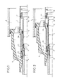
- La figure 1 est une vue partielle en coupe longitudinale d'un disjoncteur conforme à l'invention en position fermée.
- La figure 2 est une vue partielle en coupe longitudinale d'un disjoncteur conforme à l'invention en position intermédiaire d'ouverture.
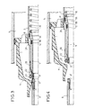
- La figure 3 est une vue partielle en coupe longitudinale d'un disjoncteur conforme à l'invention en position de début d'arc.
- La figure 4 est une vue partielle en coupe longitudinale d'un disjoncteur conforme à l'invention en position ouverte.
- Une enveloppe cylindrique, par exemple en porcelaine, délimite un volume intérieur étanche rempli de gaz à bonnes propriétés diélectriques tel que du SF6, pur ou mélangé à de l'azote, sous une pression de quelques bars.
- Le premier contact en bout fixe 8 du disjoncteur est constitué d'un tube métallique relié à un bloc traversant l'enveloppe de manière étanche et relié à une première prise de courant. L'extrémité 8' du tube 8 est réalisée en un alliage résistant aux effets d'arc, par exemple à base de tungstène.
- Le second contact en bout mobile 9 est constitué d'un tube métallique, dont l'extrémité 9' qui coopère avec le contact 8 est également réalisé en alliage résistant à l'arc. Ce tube 9 présente près de son extrémité opposée à l'extrémité 9', un perçage latéral 9B pour l'évacuation du gaz. Cette extrémité 9A est annulaire de diamètre supérieur à celui du tube 9 et est coulissante dans un tube 2.
- Ce tube 2 peut être déplacé par une tringle de manoeuvre et il est relié à une seconde prise de courant. Il définit avec un second tube un volume de soufflage 5 et il est prolongé par une buse de soufflage 4.
- L'équipage mobile est donc constitué de ce tube 2 entraîné en translation et du second contact 9 semi mobile par coulissement dans le tube 2 et poussé sur son extrémité annulaire 9A par la première extrémité d'un ressort 10 en appui par sa seconde extrémité sur un épaulement annulaire du tube 2.
- L'extrémité tournée vers le contact fixe 8 du tube 2 comporte une partie annulaire 2A qui coopère par butée avec l'extrémité annulaire 9A du contact semi mobile 9 pour l'ouverture des contacts en bout 8,9, comme il sera vu plus précisément plus loin.
- L'extrémité annulaire 9A est guidée par rapport au tube 2 par un segment isolant 11 et l'extrémité annulaire 2A est guidée par rapport au tube 9 par un segment isolant 12.
- Cette extrémité annulaire 2A porte un contact constitué d'une couronne de bras de contact 20 glissant sur le contact fixe 8 par l'intermédiaire d'un plot de contact d'arc 21 et d'un bourrelet de contact permanent 22, disposé à proximité de ce plot 21.
- Selon des caractéristiques constitutives importantes, dont la fonction sera comprise à la lecture du fonctionnement du disjoncteur,
- - la différence des longueurs du second contact en bout 9 et de son extrémité annulaire 9A est légèrement supérieure à la somme des longueurs desdits bras 20 et de l'extrémité annulaire 2A à laquelle ils sont solidaires,
- - le diamètre extérieur du premier contact en bout 8 est légèrement supérieur à celui du second contact en bout 9,
- - les diamètres intérieurs du plot 21 et du bourrelet 22 sont inférieurs au diamètre extérieur du second contact 9, à l'état libre, les bras 20 étant relativement flexibles radialement,
- - le diamètre intérieur du bourrelet 22 est légèrement inférieur à celui du plot 21.
- Le plot de contact d'arc 21 est en matériau résistant à l'arc, par exemple à base de tungstène, tandis que le bourrelet de contact permanent 22 est en métal conducteur classique comme les bras 20.
- Le fonctionnement du disjoncteur va maintenant être décrit en détail.
- En position fermée telle que représentée sur la figure 1, les contacts en bout 8 et 9 sont aboutés, les bourrelets 22 sont en contact avec la surface latérale du contact fixe 8 et les plots 21 sont très légèrement écartés de cette surface latérale; le courant permanent représenté par une flèche passe de la première prise de courant vers la seconde prise de courant par le tube 8, les bourrelets 22, les bras 20 et le tube 2.
- Dans la position intermédiaire représentée sur la figure 2, lorsque les bourrelets 22 quittent la surface latérale du contact fixe 8, compte tenu des dimensions précisées ci-dessus, il existe un léger jeu entre les bourrelets 22 et le contact semi mobile 9 et les plots 21 sont par contre en contact avec la surface latérale du contact fixe 8; le courant permanent ou de court-circuit représenté par une flèche passe alors de la première prise à la seconde prise de courant par le tube 8, les plots 21 et le tube 2.
- Dans la position de début d'arc représentée sur la figure 3, l'extrémité annulaire 2A vient en butée avec l'extrémité annulaire 9A et, compte tenu des dispositions dimensionnelles déjà précisées, les plots 21 sont à une petite distance du contact fixe 8 qui est toujours abouté avec le contact semi mobile 9; le courant, représenté par une flèche, passe alors de la première prise à la seconde prise de courant par le tube 8, le tube 9, les plots 22, les bras 20 et le tube 2; en cas de courants de court circuit élevés et de forces de répulsion résultantes, le contact semi mobile 9 peut s'écarter sans dommages selon la ligne en pointillés; en effet, l'arc créé entre l'extrémité 8' du contact fixe 8 et l'extrémité 9' du contact semi mobile 9 est alors transféré très rapidement entre l'extrémité 8' du contact fixe 8 et le plot 21, dès que la distance entre les contacts en bout 8 et 9 dépasse celle entre le contact 8 et les plots 21.
- L'ouverture est alors terminée par séparation des contacts en bout 8 et 9, le tube 2 entraînant le contact 9, comme il est représenté sur la figure 4.
- Le fonctionnement a été décrit ci-dessus pour une opération d'ouverture. En fermeture, les déplacements sont inversés.
- Grâce à l'invention, le problème causé par la répulsion des contacts en bout 8 et 9 est résolu tout autant à la séparation de ces contacts à l'ouverture, qu'à l'entrée en contact de ces contacts à la fermeture.
- Le disjoncteur pourrait fonctionner sans contacts en bout, c'est à dire en supprimant le tube 9, avec seulement une tulipe de bras 20 telle que précédemment décrite. Les contacts en bout 8 et 9 permettent une coupure rapide et des temps d'arc particulièrement courts. L'usure de l'appareil est ainsi réduit.
- Par ailleurs, la présence des plots 21 en alliage résistant à l'arc protègent les bourrelets 22 métalliques, de préférence en cuivre, des effets destructeurs de l'arc électrique, ces bourrelets 22 étant destinés au passage du courant permanent.
Claims (4)
Applications Claiming Priority (2)
| Application Number | Priority Date | Filing Date | Title |
|---|---|---|---|
| FR9109887 | 1991-08-02 | ||
| FR9109887A FR2680044B1 (fr) | 1991-08-02 | 1991-08-02 | Disjoncteur a moyenne ou haute tension a contacts d'arc en bout. |
Publications (2)
| Publication Number | Publication Date |
|---|---|
| EP0525716A1 true EP0525716A1 (fr) | 1993-02-03 |
| EP0525716B1 EP0525716B1 (fr) | 1997-11-26 |
Family
ID=9415891
Family Applications (1)
| Application Number | Title | Priority Date | Filing Date |
|---|---|---|---|
| EP92112850A Expired - Lifetime EP0525716B1 (fr) | 1991-08-02 | 1992-08-01 | Disjoncteur à moyenne ou haute tension à contacts d'arc en bout |
Country Status (11)
| Country | Link |
|---|---|
| US (1) | US5258590A (fr) |
| EP (1) | EP0525716B1 (fr) |
| JP (1) | JPH0793076B2 (fr) |
| CN (1) | CN1028134C (fr) |
| AT (1) | ATE160647T1 (fr) |
| BR (1) | BR9202992A (fr) |
| CA (1) | CA2074893C (fr) |
| DE (1) | DE69223292T2 (fr) |
| DK (1) | DK0525716T3 (fr) |
| ES (1) | ES2110455T3 (fr) |
| FR (1) | FR2680044B1 (fr) |
Cited By (4)
| Publication number | Priority date | Publication date | Assignee | Title |
|---|---|---|---|---|
| EP0641002A1 (fr) * | 1993-08-30 | 1995-03-01 | Gec Alsthom T Et D Sa | Disjoncteur à haute ou moyenne tension à contacts en bout |
| FR2709866A1 (fr) * | 1993-09-08 | 1995-03-17 | Gec Alsthom T & D Sa | Disjoncteur à contacts en bout et à grande tension d'arc. |
| FR2762925A1 (fr) * | 1997-05-02 | 1998-11-06 | Gec Alsthom T & D Sa | Disjoncteur a haute tension a double mouvement des contacts d'arc |
| WO2012072410A1 (fr) * | 2010-12-02 | 2012-06-07 | Siemens Aktiengesellschaft | Montage de contacts électriques |
Families Citing this family (9)
| Publication number | Priority date | Publication date | Assignee | Title |
|---|---|---|---|---|
| CN101599391B (zh) * | 2009-07-13 | 2013-02-27 | 西安森源配电自动化设备有限公司 | 单断口单气缸自能式高压六氟化硫断路器灭弧室 |
| FR2962253B1 (fr) | 2010-07-01 | 2012-08-31 | Areva T & D Sas | Chambre de coupure pour disjoncteur a moyenne ou haute tension a energie de man?uvre et dimensions reduites |
| CN102290278B (zh) * | 2011-08-04 | 2015-04-22 | 中国西电电气股份有限公司 | 用于电开关设备的引弧装置 |
| JP6157824B2 (ja) * | 2012-09-28 | 2017-07-05 | 株式会社東芝 | ガス遮断器 |
| JP6289856B2 (ja) * | 2013-10-16 | 2018-03-07 | 株式会社東芝 | ガス遮断器 |
| JP2017050048A (ja) * | 2015-08-31 | 2017-03-09 | 株式会社日立製作所 | ガス遮断器 |
| CN105977073B (zh) * | 2016-06-07 | 2018-07-06 | 平高集团有限公司 | 喷口连接结构及使用该结构的灭弧室和断路器 |
| EP3561840B1 (fr) | 2016-12-16 | 2024-07-10 | Toshiba Energy Systems & Solutions Corporation | Dispositif de commutation à isolation gazeuse |
| US11380501B2 (en) * | 2019-12-31 | 2022-07-05 | Southern States Llc | High voltage electric power switch with carbon arcing electrodes and carbon dioxide dielectric gas |
Citations (5)
| Publication number | Priority date | Publication date | Assignee | Title |
|---|---|---|---|---|
| BE382647A (fr) * | ||||
| DE946638C (de) * | 1951-04-06 | 1956-08-02 | Sachsenwerk Licht & Kraft Ag | Schubtrennschalter fuer zusaetzliche Lastabschaltung |
| CH327093A (de) * | 1954-10-28 | 1958-01-15 | Tokyo Shibaura Electric Co | Schalter mit Lichtbogenlöschung durch einen Druckmittelstrom |
| CH519773A (de) * | 1970-08-14 | 1972-02-29 | Bbc Brown Boveri & Cie | Kontaktanordnung für Druckgasschalter |
| FR2172980A1 (fr) * | 1972-02-22 | 1973-10-05 | Siemens Ag |
Family Cites Families (3)
| Publication number | Priority date | Publication date | Assignee | Title |
|---|---|---|---|---|
| JPS61177337U (fr) * | 1985-04-19 | 1986-11-05 | ||
| JPS62197232U (fr) * | 1986-06-04 | 1987-12-15 | ||
| JPS6345721A (ja) * | 1986-06-06 | 1988-02-26 | 三菱電機株式会社 | 開閉器 |
-
1991
- 1991-08-02 FR FR9109887A patent/FR2680044B1/fr not_active Expired - Fee Related
-
1992
- 1992-07-28 US US07/920,842 patent/US5258590A/en not_active Expired - Fee Related
- 1992-07-30 CA CA002074893A patent/CA2074893C/fr not_active Expired - Fee Related
- 1992-07-31 JP JP4205772A patent/JPH0793076B2/ja not_active Expired - Fee Related
- 1992-07-31 BR BR929202992A patent/BR9202992A/pt not_active IP Right Cessation
- 1992-08-01 DE DE69223292T patent/DE69223292T2/de not_active Expired - Fee Related
- 1992-08-01 AT AT92112850T patent/ATE160647T1/de not_active IP Right Cessation
- 1992-08-01 ES ES92112850T patent/ES2110455T3/es not_active Expired - Lifetime
- 1992-08-01 CN CN92108998.8A patent/CN1028134C/zh not_active Expired - Fee Related
- 1992-08-01 EP EP92112850A patent/EP0525716B1/fr not_active Expired - Lifetime
- 1992-08-01 DK DK92112850.0T patent/DK0525716T3/da active
Patent Citations (5)
| Publication number | Priority date | Publication date | Assignee | Title |
|---|---|---|---|---|
| BE382647A (fr) * | ||||
| DE946638C (de) * | 1951-04-06 | 1956-08-02 | Sachsenwerk Licht & Kraft Ag | Schubtrennschalter fuer zusaetzliche Lastabschaltung |
| CH327093A (de) * | 1954-10-28 | 1958-01-15 | Tokyo Shibaura Electric Co | Schalter mit Lichtbogenlöschung durch einen Druckmittelstrom |
| CH519773A (de) * | 1970-08-14 | 1972-02-29 | Bbc Brown Boveri & Cie | Kontaktanordnung für Druckgasschalter |
| FR2172980A1 (fr) * | 1972-02-22 | 1973-10-05 | Siemens Ag |
Cited By (7)
| Publication number | Priority date | Publication date | Assignee | Title |
|---|---|---|---|---|
| EP0641002A1 (fr) * | 1993-08-30 | 1995-03-01 | Gec Alsthom T Et D Sa | Disjoncteur à haute ou moyenne tension à contacts en bout |
| FR2709597A1 (fr) * | 1993-08-30 | 1995-03-10 | Gec Alsthom T & D Sa | Disjoncteur à moyenne ou haute tension à contacts en bout. |
| FR2709866A1 (fr) * | 1993-09-08 | 1995-03-17 | Gec Alsthom T & D Sa | Disjoncteur à contacts en bout et à grande tension d'arc. |
| FR2762925A1 (fr) * | 1997-05-02 | 1998-11-06 | Gec Alsthom T & D Sa | Disjoncteur a haute tension a double mouvement des contacts d'arc |
| WO2012072410A1 (fr) * | 2010-12-02 | 2012-06-07 | Siemens Aktiengesellschaft | Montage de contacts électriques |
| RU2599777C2 (ru) * | 2010-12-02 | 2016-10-20 | Сименс Акциенгезелльшафт | Электрическое контактное устройство |
| US9524837B2 (en) | 2010-12-02 | 2016-12-20 | Siemens Aktiengesellschaft | Electrical contact arrangement |
Also Published As
| Publication number | Publication date |
|---|---|
| BR9202992A (pt) | 1993-03-30 |
| DK0525716T3 (da) | 1998-05-18 |
| DE69223292T2 (de) | 1998-03-26 |
| US5258590A (en) | 1993-11-02 |
| FR2680044A1 (fr) | 1993-02-05 |
| DE69223292D1 (de) | 1998-01-08 |
| JPH0793076B2 (ja) | 1995-10-09 |
| ES2110455T3 (es) | 1998-02-16 |
| FR2680044B1 (fr) | 1995-01-20 |
| EP0525716B1 (fr) | 1997-11-26 |
| CA2074893A1 (fr) | 1993-02-03 |
| CA2074893C (fr) | 1996-05-21 |
| CN1028134C (zh) | 1995-04-05 |
| CN1069363A (zh) | 1993-02-24 |
| JPH05198235A (ja) | 1993-08-06 |
| ATE160647T1 (de) | 1997-12-15 |
Similar Documents
| Publication | Publication Date | Title |
|---|---|---|
| EP0525716B1 (fr) | Disjoncteur à moyenne ou haute tension à contacts d'arc en bout | |
| EP0577530B1 (fr) | Interrupteur ou disjoncteur à auto-expansion | |
| EP2182536A1 (fr) | Interrupteur de courant sur une ligne électrique comprenant une ampoule à vide | |
| FR2512267A1 (fr) | Disjoncteur a gaz comprime muni de resistances d'ouverture et de fermeture | |
| EP0807945B1 (fr) | Disjoncteur à haute tension avec insertion de résistance à la fermeture | |
| EP0380907B1 (fr) | Disjoncteur à haute et moyenne tension à gaz de soufflage | |
| FR2467477A1 (fr) | Disjoncteur pneumatique | |
| EP0454035A1 (fr) | Disjoncteur à moyenne ou haute tension à contacts d'arc en bout | |
| EP0398213B1 (fr) | Disjoncteur à moyenne tension à courant nominal élevé | |
| EP0450567B1 (fr) | Disjoncteur à haute ou moyenne tension à contacts d'arc en bout | |
| EP0759629B1 (fr) | Disjoncteur muni d'une résistance de fermeture avec dispositif d'insertion | |
| FR2650911A1 (fr) | Disjoncteur a moyenne tension | |
| EP0458236B1 (fr) | Disjoncteur à moyenne tension | |
| CA2041234C (fr) | Disjoncteur a haute tension a arc serie | |
| EP0831503B1 (fr) | Disjoncteur à haute tension avec amortisseur | |
| FR2649531A1 (fr) | Disjoncteur a haute ou moyenne tension | |
| EP2735012B1 (fr) | Sectionneur pour une installation a isolation gazeuse comportant une ampoule a vide | |
| EP2774159B1 (fr) | Appareillage electrique comportant des moyens pour limiter la formation d'un arc electrique | |
| CA1251818A (fr) | Disjoncteur haute tension a soufflage d'arc | |
| FR2509521A1 (fr) | Disjoncteur a haute tension sous enveloppe contenant un gaz isolant | |
| FR2705494A1 (fr) | Disjoncteur à manÓoeuvre assistée par voie électrodynamique. | |
| FR2665020A1 (fr) | Disjoncteur pour la coupure des courants eleves. | |
| FR2751781A1 (fr) | Disjoncteur avec insertion temporaire de resistance a la fermeture | |
| FR2849265A1 (fr) | Interrupteur magnetique | |
| FR2720544A1 (fr) | Disjoncteur à ouverture assistée par effet électro-dynamique. |
Legal Events
| Date | Code | Title | Description |
|---|---|---|---|
| PUAI | Public reference made under article 153(3) epc to a published international application that has entered the european phase |
Free format text: ORIGINAL CODE: 0009012 |
|
| AK | Designated contracting states |
Kind code of ref document: A1 Designated state(s): AT BE CH DE DK ES FR GB GR IE IT LI LU MC NL PT SE |
|
| 17P | Request for examination filed |
Effective date: 19930726 |
|
| 17Q | First examination report despatched |
Effective date: 19950607 |
|
| GRAG | Despatch of communication of intention to grant |
Free format text: ORIGINAL CODE: EPIDOS AGRA |
|
| GRAH | Despatch of communication of intention to grant a patent |
Free format text: ORIGINAL CODE: EPIDOS IGRA |
|
| GRAH | Despatch of communication of intention to grant a patent |
Free format text: ORIGINAL CODE: EPIDOS IGRA |
|
| GRAA | (expected) grant |
Free format text: ORIGINAL CODE: 0009210 |
|
| AK | Designated contracting states |
Kind code of ref document: B1 Designated state(s): AT BE CH DE DK ES FR GB GR IE IT LI LU MC NL PT SE |
|
| PG25 | Lapsed in a contracting state [announced via postgrant information from national office to epo] |
Ref country code: GR Free format text: LAPSE BECAUSE OF FAILURE TO SUBMIT A TRANSLATION OF THE DESCRIPTION OR TO PAY THE FEE WITHIN THE PRESCRIBED TIME-LIMIT Effective date: 19971126 |
|
| REF | Corresponds to: |
Ref document number: 160647 Country of ref document: AT Date of ref document: 19971215 Kind code of ref document: T |
|
| REG | Reference to a national code |
Ref country code: CH Ref legal event code: NV Representative=s name: GEC ALSTHOM SALES NETWORK SA Ref country code: CH Ref legal event code: EP |
|
| GBT | Gb: translation of ep patent filed (gb section 77(6)(a)/1977) |
Effective date: 19971126 |
|
| REF | Corresponds to: |
Ref document number: 69223292 Country of ref document: DE Date of ref document: 19980108 |
|
| ITF | It: translation for a ep patent filed | ||
| REG | Reference to a national code |
Ref country code: ES Ref legal event code: FG2A Ref document number: 2110455 Country of ref document: ES Kind code of ref document: T3 |
|
| PG25 | Lapsed in a contracting state [announced via postgrant information from national office to epo] |
Ref country code: PT Free format text: LAPSE BECAUSE OF FAILURE TO SUBMIT A TRANSLATION OF THE DESCRIPTION OR TO PAY THE FEE WITHIN THE PRESCRIBED TIME-LIMIT Effective date: 19980226 |
|
| REG | Reference to a national code |
Ref country code: DK Ref legal event code: T3 |
|
| PG25 | Lapsed in a contracting state [announced via postgrant information from national office to epo] |
Ref country code: IE Free format text: LAPSE BECAUSE OF NON-PAYMENT OF DUE FEES Effective date: 19980714 |
|
| REG | Reference to a national code |
Ref country code: IE Ref legal event code: FD4D Ref document number: 77526 Country of ref document: IE |
|
| PG25 | Lapsed in a contracting state [announced via postgrant information from national office to epo] |
Ref country code: LU Free format text: LAPSE BECAUSE OF NON-PAYMENT OF DUE FEES Effective date: 19980801 |
|
| PLBE | No opposition filed within time limit |
Free format text: ORIGINAL CODE: 0009261 |
|
| STAA | Information on the status of an ep patent application or granted ep patent |
Free format text: STATUS: NO OPPOSITION FILED WITHIN TIME LIMIT |
|
| 26N | No opposition filed | ||
| PG25 | Lapsed in a contracting state [announced via postgrant information from national office to epo] |
Ref country code: MC Free format text: LAPSE BECAUSE OF NON-PAYMENT OF DUE FEES Effective date: 19990228 |
|
| REG | Reference to a national code |
Ref country code: GB Ref legal event code: IF02 |
|
| PGFP | Annual fee paid to national office [announced via postgrant information from national office to epo] |
Ref country code: GB Payment date: 20040730 Year of fee payment: 13 |
|
| PGFP | Annual fee paid to national office [announced via postgrant information from national office to epo] |
Ref country code: DE Payment date: 20040805 Year of fee payment: 13 |
|
| PGFP | Annual fee paid to national office [announced via postgrant information from national office to epo] |
Ref country code: CH Payment date: 20040806 Year of fee payment: 13 |
|
| PGFP | Annual fee paid to national office [announced via postgrant information from national office to epo] |
Ref country code: SE Payment date: 20040809 Year of fee payment: 13 |
|
| PGFP | Annual fee paid to national office [announced via postgrant information from national office to epo] |
Ref country code: DK Payment date: 20040810 Year of fee payment: 13 Ref country code: AT Payment date: 20040810 Year of fee payment: 13 |
|
| PGFP | Annual fee paid to national office [announced via postgrant information from national office to epo] |
Ref country code: NL Payment date: 20040818 Year of fee payment: 13 |
|
| BECN | Be: change of holder's name |
Owner name: *ALSTOM HOLDINGS Effective date: 20040820 |
|
| NLT1 | Nl: modifications of names registered in virtue of documents presented to the patent office pursuant to art. 16 a, paragraph 1 |
Owner name: ALSTOM HOLDINGS Owner name: ALSTOM FRANCE SA |
|
| REG | Reference to a national code |
Ref country code: CH Ref legal event code: PFA Owner name: ALSTOM FRANCE S.A. Free format text: GEC ALSTHOM SA#38, AVENUE KLEBER#75116 PARIS (FR) -TRANSFER TO- ALSTOM FRANCE S.A.#38, AVENUE KLEBER#75116 PARIS (FR) Ref country code: CH Ref legal event code: PFA Owner name: ALSTOM HOLDINGS Free format text: ALSTOM FRANCE S.A.#38, AVENUE KLEBER#75116 PARIS (FR) -TRANSFER TO- ALSTOM HOLDINGS#25, AVENUE KLEBER#75116 PARIS (FR) |
|
| REG | Reference to a national code |
Ref country code: FR Ref legal event code: CD |
|
| REG | Reference to a national code |
Ref country code: FR Ref legal event code: CD |
|
| PG25 | Lapsed in a contracting state [announced via postgrant information from national office to epo] |
Ref country code: AT Free format text: LAPSE BECAUSE OF NON-PAYMENT OF DUE FEES Effective date: 20050801 Ref country code: GB Free format text: LAPSE BECAUSE OF NON-PAYMENT OF DUE FEES Effective date: 20050801 |
|
| PG25 | Lapsed in a contracting state [announced via postgrant information from national office to epo] |
Ref country code: SE Free format text: LAPSE BECAUSE OF NON-PAYMENT OF DUE FEES Effective date: 20050802 |
|
| PG25 | Lapsed in a contracting state [announced via postgrant information from national office to epo] |
Ref country code: CH Free format text: LAPSE BECAUSE OF NON-PAYMENT OF DUE FEES Effective date: 20050831 Ref country code: LI Free format text: LAPSE BECAUSE OF NON-PAYMENT OF DUE FEES Effective date: 20050831 Ref country code: DK Free format text: LAPSE BECAUSE OF NON-PAYMENT OF DUE FEES Effective date: 20050831 |
|
| PGFP | Annual fee paid to national office [announced via postgrant information from national office to epo] |
Ref country code: BE Payment date: 20051013 Year of fee payment: 14 |
|
| BECA | Be: change of holder's address |
Owner name: S.A. *AREVA T&D1 PLACE DE LA COUPOLE, TOUR AREVA, Effective date: 20051124 |
|
| PG25 | Lapsed in a contracting state [announced via postgrant information from national office to epo] |
Ref country code: DE Free format text: LAPSE BECAUSE OF NON-PAYMENT OF DUE FEES Effective date: 20060301 Ref country code: NL Free format text: LAPSE BECAUSE OF NON-PAYMENT OF DUE FEES Effective date: 20060301 |
|
| REG | Reference to a national code |
Ref country code: CH Ref legal event code: PL |
|
| REG | Reference to a national code |
Ref country code: DK Ref legal event code: EBP |
|
| REG | Reference to a national code |
Ref country code: FR Ref legal event code: TP |
|
| EUG | Se: european patent has lapsed | ||
| GBPC | Gb: european patent ceased through non-payment of renewal fee |
Effective date: 20050801 |
|
| NLV4 | Nl: lapsed or anulled due to non-payment of the annual fee |
Effective date: 20060301 |
|
| PG25 | Lapsed in a contracting state [announced via postgrant information from national office to epo] |
Ref country code: BE Free format text: LAPSE BECAUSE OF NON-PAYMENT OF DUE FEES Effective date: 20060831 |
|
| BECA | Be: change of holder's address |
Owner name: S.A. *AREVA T&D1 PLACE DE LA COUPOLE, TOUR AREVA, Effective date: 20051124 |
|
| BERE | Be: lapsed |
Owner name: S.A. *AREVA T&D Effective date: 20060831 |
|
| PGFP | Annual fee paid to national office [announced via postgrant information from national office to epo] |
Ref country code: ES Payment date: 20110812 Year of fee payment: 20 Ref country code: FR Payment date: 20110901 Year of fee payment: 20 |
|
| PGFP | Annual fee paid to national office [announced via postgrant information from national office to epo] |
Ref country code: IT Payment date: 20110824 Year of fee payment: 20 |
|
| REG | Reference to a national code |
Ref country code: FR Ref legal event code: TP Owner name: SCHNEIDER ELECTRIC ENERGY FRANCE, FR Effective date: 20120806 |
|
| REG | Reference to a national code |
Ref country code: ES Ref legal event code: FD2A Effective date: 20130718 |
|
| PG25 | Lapsed in a contracting state [announced via postgrant information from national office to epo] |
Ref country code: ES Free format text: LAPSE BECAUSE OF EXPIRATION OF PROTECTION Effective date: 20120802 |