EP0525457B1 - Organe de contact à displacement d'isolant - Google Patents
Organe de contact à displacement d'isolant Download PDFInfo
- Publication number
- EP0525457B1 EP0525457B1 EP92111624A EP92111624A EP0525457B1 EP 0525457 B1 EP0525457 B1 EP 0525457B1 EP 92111624 A EP92111624 A EP 92111624A EP 92111624 A EP92111624 A EP 92111624A EP 0525457 B1 EP0525457 B1 EP 0525457B1
- Authority
- EP
- European Patent Office
- Prior art keywords
- contact
- slot
- insulation displacement
- legs
- spring material
- Prior art date
- Legal status (The legal status is an assumption and is not a legal conclusion. Google has not performed a legal analysis and makes no representation as to the accuracy of the status listed.)
- Expired - Lifetime
Links
Images
Classifications
-
- H—ELECTRICITY
- H01—ELECTRIC ELEMENTS
- H01R—ELECTRICALLY-CONDUCTIVE CONNECTIONS; STRUCTURAL ASSOCIATIONS OF A PLURALITY OF MUTUALLY-INSULATED ELECTRICAL CONNECTING ELEMENTS; COUPLING DEVICES; CURRENT COLLECTORS
- H01R4/00—Electrically-conductive connections between two or more conductive members in direct contact, i.e. touching one another; Means for effecting or maintaining such contact; Electrically-conductive connections having two or more spaced connecting locations for conductors and using contact members penetrating insulation
- H01R4/24—Connections using contact members penetrating or cutting insulation or cable strands
- H01R4/2416—Connections using contact members penetrating or cutting insulation or cable strands the contact members having insulation-cutting edges, e.g. of tuning fork type
- H01R4/242—Connections using contact members penetrating or cutting insulation or cable strands the contact members having insulation-cutting edges, e.g. of tuning fork type the contact members being plates having a single slot
- H01R4/2425—Flat plates, e.g. multi-layered flat plates
-
- H—ELECTRICITY
- H01—ELECTRIC ELEMENTS
- H01R—ELECTRICALLY-CONDUCTIVE CONNECTIONS; STRUCTURAL ASSOCIATIONS OF A PLURALITY OF MUTUALLY-INSULATED ELECTRICAL CONNECTING ELEMENTS; COUPLING DEVICES; CURRENT COLLECTORS
- H01R2201/00—Connectors or connections adapted for particular applications
- H01R2201/16—Connectors or connections adapted for particular applications for telephony
Definitions
- the invention relates to an insulation displacement contact element for stripping-free connection of electrical conductors, in particular in telecommunications and data technology, made of metallic leaf spring material with two separate contact legs rigidly interconnected at one end along the contact slot.
- An insulation displacement contact element of the generic type is previously known from DE 33 11 447 A1.
- the contact limbs delimiting the contact slot are interlaced with one another, so that an additional torsional force acts on the actual clamping point.
- the disadvantage here is that an acute-angled, V-shaped contact slot is formed by interlacing the two contact legs against each other is, which due to its different widths in the longitudinal direction of the contact slot no uniform contacting when connecting electrical conductors, especially very thin wires or strands, allows.
- the bend in the two contact legs and thus the opening of the contact slot becomes greater the deeper the electrical conductor is pressed into the contact slot.
- the opening width of the contact slot in the entrance area depends on the length of the contact slot and the greater the longer the length of the contact slot.
- there is a relatively large bending of the contact limbs when electrical conductors are connected as a result of which relatively large forces act on the housing receiving the insulation displacement contact element. These forces are increased by the additional torsional force that occurs.
- connection element which is provided with three or more prongs between which postage indicia are provided.
- the frankings have different widths in order to connect different cable core diameters.
- the formation of V-shaped contact slots results in a relatively large bending of the contact legs when the cable wires are connected, with relatively large forces being generated.
- the invention is therefore based on the object of improving an insulation displacement contact element of the generic type in such a way that there is a relatively uniform contact force for connecting electrical conductors over the entire length of the contact slot.
- the invention provides that the contact legs are each shifted by about half the material thickness of the leaf spring material to the front and rear thereof, the contact edges of the contact legs delimiting the contact slot being arranged parallel to one another over their entire length.
- a uniform width of the contact slot is achieved over its entire length, the width of the contact slot being in the range from 0 to 0.05 mm.
- the contact legs are each twisted relative to one another by about half the material thickness of the leaf spring material, the contact edges of the contact legs delimiting the contact slot being arranged parallel to one another over their entire length. This also results in an extremely small width of the contact slot, so that very thin wires or strands can be safely connected as electrical conductors. Greater stiffness of the insulation displacement contact element is also achieved without forces acting on the housing receiving the insulation displacement contact element.
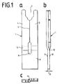
- the insulation displacement contact element 1 for the stripping-free connection of electrical conductors 2, in particular very thin wires and strands of telecommunications and data technology, consists of a metallic leaf spring material of thickness D, which, through a contact slot 3 extending over part of the total length, in two contact legs 4, 5 is divided, which are rigidly connected to one another with a common end part 6.
- the contact slot 3 extends from the bottom of the stepped, approximately V-shaped entrance area 7 to the upper end of an oval relief opening 8 in the transition area of the two contact legs 4, 5 to the end part 6.
- the insulation displacement contact element 1 shown in FIG a punching process is produced, in which the input area 7, the contact slot 3 and the relief opening 8 are formed.
- the contact legs 4, 5 are each shifted by half the material thickness D of the leaf spring material to its front and rear sides 9, 10, the contact edges 11 of both contact legs delimiting the contact slot 3 4, 5 are aligned parallel to each other over their entire length.
- the two contact legs 4, 5 are in the area of the relief opening 8 to the front or. Back 9, 10 of the insulation displacement contact element 1 displaced, resulting in displacement zones 12 which lie approximately in the central longitudinal region of the relief opening 8.
- the insulation displacement contact element 1 enables the reliable contacting of copper wires with a diameter of 0.25 to 0.90 mm and also the secure contacting of stranded wires.
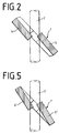
- the insulation displacement contact element 1 can be used as a fork contact or as an angle contact, the angle of the plane of the insulation displacement contact element 1 relative to the conductor 2 being between 30 ° and 60 °.
- FIG. 2 shows the most common contact position of 45 ° between the insulation displacement contact element 1 and the conductor 2.
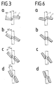
- FIG. 3 shows various possible contact positions with angles between 90 ° and 30 ° for different purposes. It is essential that the parallelism of the contact legs 4, 5 to one another is maintained for all purposes.
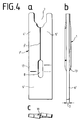
- FIG. 4 shows the second embodiment of the insulation displacement contact element 1 ', which has a contact slot 3' with these limiting contact legs 4 ', 5' and an end part 6 'rigidly connected to the latter.
- the entrance area 7 and the relief opening 8 are present in the same way as in the embodiment according to FIGS. 1 to 3.
- the contact legs 4 ', 5' are each twisted against each other by half the material thickness D of the leaf spring material, the contact edges 11 'of the contact legs 4', 5 'delimiting the contact slot 3' being arranged parallel to one another over their entire length.
- the contact legs 4 ', 5' over their entire length with respect to the end part 6 'in the direction rotated on the front and back 9, 10, as can be seen in the top view in FIG. 4c.
- a shift of the contact legs 4 ', 5' against each other does not take place.
- the twisting zone 13 lies in the region of the relief opening 8, as shown in FIG. 4a.
- 5 shows the connection of a conductor 2 to the contact legs 4 ', 5' of an insulation displacement contact element 1 'in the second embodiment in the 45 ° position.
- 6 shows various other possible contact positions between the 90 ° position (fork contact) and the 30 ° position.
Landscapes
- Connections By Means Of Piercing Elements, Nuts, Or Screws (AREA)
- Coupling Device And Connection With Printed Circuit (AREA)
- Glass Compositions (AREA)
- Multi-Conductor Connections (AREA)
- Connections Arranged To Contact A Plurality Of Conductors (AREA)
- Scissors And Nippers (AREA)
- Control Of El Displays (AREA)
- Control Of Indicators Other Than Cathode Ray Tubes (AREA)
- Semiconductor Memories (AREA)
- Manufacturing Of Electrical Connectors (AREA)
Claims (2)
- Organe de contact (1) à displacement d'isolant pour le raccordement sans dénudage de conducteurs électriques dans la technique de la télécommunication et des données, constitué d'une matière de ressort à lames avec deux jambes de contact (4, 5) séparées le long de la fente de contact (3) et liées rigidement l'une à l'autre à leur extrémité,
caractérisé en ce que les jambes de contact (4, 5) sont déplacées par environ la moitié de l'épaisseur (D) de la matière de ressort à lames vers sa face avant et arrière (9, 10), les arêtes de contact (11) des jambes de contact (4, 5) limitant la fente de contact (3) étant parallèles l'une à l'autre sur leur longueur complète, et que la largeur de la fente de contact (3) est dans le domaine de 0 à 0,5 mm en état de repos. - Organe de contact (1') à displacement d'isolant pour le raccordement sans dénudage de conducteurs électriques dans la technique de la télécommunication et des données, constitué d'une matière de ressort à lames avec deux jambes de contact (4', 5') séparées le long de la fente de contact (3') et liées rigidement l'une à l'autre à leur extrémité,
caractérisé en ce que les jambes de contact (4', 5') sont tordues l'une par rapport à l'autre par environ la moitié de l'épaisseur (D) de la matière de ressort à lames, les arêtes de contact (11) des jambes de contact (4', 5') limitant la fente de contact (3') étant parallèles l'une à l'autre sur leur longueur complète, et que la largeur de la fente de contact (3') est dans le domaine de 0 à 0,5 mm en état de repos.
Applications Claiming Priority (2)
| Application Number | Priority Date | Filing Date | Title |
|---|---|---|---|
| DE4126068 | 1991-08-02 | ||
| DE4126068A DE4126068C1 (fr) | 1991-08-02 | 1991-08-02 |
Publications (3)
| Publication Number | Publication Date |
|---|---|
| EP0525457A2 EP0525457A2 (fr) | 1993-02-03 |
| EP0525457A3 EP0525457A3 (en) | 1993-05-26 |
| EP0525457B1 true EP0525457B1 (fr) | 1996-03-06 |
Family
ID=6437821
Family Applications (1)
| Application Number | Title | Priority Date | Filing Date |
|---|---|---|---|
| EP92111624A Expired - Lifetime EP0525457B1 (fr) | 1991-08-02 | 1992-07-09 | Organe de contact à displacement d'isolant |
Country Status (7)
| Country | Link |
|---|---|
| EP (1) | EP0525457B1 (fr) |
| AT (1) | ATE135142T1 (fr) |
| DE (2) | DE4126068C1 (fr) |
| DK (1) | DK0525457T3 (fr) |
| ES (1) | ES2084885T3 (fr) |
| GR (1) | GR3019244T3 (fr) |
| IE (1) | IE78623B1 (fr) |
Cited By (1)
| Publication number | Priority date | Publication date | Assignee | Title |
|---|---|---|---|---|
| US6837735B1 (en) | 1998-05-28 | 2005-01-04 | Tyco Electronics Logistics Ag | RF connector with cutting edges |
Families Citing this family (6)
| Publication number | Priority date | Publication date | Assignee | Title |
|---|---|---|---|---|
| DE4323286C2 (de) * | 1993-07-12 | 1997-07-03 | Quante Ag | Schneidklemm-Kontaktelement und Verfahren zur Herstellung eines Schneidklemm-Kontaktelements |
| CA2144226C (fr) * | 1994-03-29 | 2000-05-16 | Andreas Janczak | Contact a deplacement d'isolant |
| DE19519091C1 (de) * | 1995-05-24 | 1996-06-05 | Siemens Ag | Schneidklemme zum Anschließen von isolierten elektrischen Schaltdrähten |
| DE50000619D1 (de) * | 2000-02-04 | 2002-11-14 | Siemens Ag | Schneidklemmkontakt und Verbindungsklemme |
| GB2387040B (en) * | 2002-03-28 | 2004-03-10 | Wheeler & Clinch Ltd | A contact |
| CN102364753A (zh) * | 2011-11-24 | 2012-02-29 | 刘海涛 | 一种绝缘剥移连接端子 |
Family Cites Families (4)
| Publication number | Priority date | Publication date | Assignee | Title |
|---|---|---|---|---|
| JPS5637667B2 (fr) * | 1973-11-22 | 1981-09-01 | ||
| DE3311447A1 (de) * | 1983-03-29 | 1984-10-04 | Siemens AG, 1000 Berlin und 8000 München | Anschlussklemme zum abisolierfreien anschluss elektrischer leiter in verteilern von fernmeldeanlagen, insbesondere fernsprechvermittlungsanlagen |
| GB2210514B (en) * | 1987-09-17 | 1992-02-26 | Bicc Plc | Terminating insulated conductors |
| AU6504690A (en) * | 1989-11-30 | 1991-06-26 | Siemens Aktiengesellschaft | Gripping/cutting device for use in connecting individual insulated wires |
-
1991
- 1991-08-02 DE DE4126068A patent/DE4126068C1/de not_active Expired - Lifetime
-
1992
- 1992-07-09 DE DE59205550T patent/DE59205550D1/de not_active Expired - Fee Related
- 1992-07-09 AT AT92111624T patent/ATE135142T1/de not_active IP Right Cessation
- 1992-07-09 ES ES92111624T patent/ES2084885T3/es not_active Expired - Lifetime
- 1992-07-09 DK DK92111624.0T patent/DK0525457T3/da active
- 1992-07-09 EP EP92111624A patent/EP0525457B1/fr not_active Expired - Lifetime
- 1992-07-31 IE IE922555A patent/IE78623B1/en not_active IP Right Cessation
-
1996
- 1996-03-07 GR GR960400450T patent/GR3019244T3/el unknown
Cited By (1)
| Publication number | Priority date | Publication date | Assignee | Title |
|---|---|---|---|---|
| US6837735B1 (en) | 1998-05-28 | 2005-01-04 | Tyco Electronics Logistics Ag | RF connector with cutting edges |
Also Published As
| Publication number | Publication date |
|---|---|
| GR3019244T3 (en) | 1996-06-30 |
| DE4126068C1 (fr) | 1992-12-03 |
| ES2084885T3 (es) | 1996-05-16 |
| EP0525457A3 (en) | 1993-05-26 |
| DK0525457T3 (da) | 1996-04-01 |
| EP0525457A2 (fr) | 1993-02-03 |
| ATE135142T1 (de) | 1996-03-15 |
| IE922555A1 (en) | 1993-02-10 |
| IE78623B1 (en) | 1998-02-25 |
| DE59205550D1 (de) | 1996-04-11 |
Similar Documents
| Publication | Publication Date | Title |
|---|---|---|
| EP0730785B1 (fr) | Borne de connexion pour installations electriques | |
| EP0459144B1 (fr) | Contact à borne coupante | |
| EP0893845B1 (fr) | Contact à déplacement d'isolation ainsi que bornier ou module et barette comportant un contact à déplacement d'isolation | |
| DE4403278C2 (de) | Schneidklemm-Kontaktelement | |
| CH647895A5 (de) | Elektrischer anschlussteil, verfahren zu dessen verbinden mit einem elektrischen leiter sowie verbinder mit einer mehrzahl von anschlussteilen. | |
| EP0283427B1 (fr) | Contact tubulaire tranchant à serrage | |
| EP1012914A1 (fr) | Contact enfichable | |
| EP0525457B1 (fr) | Organe de contact à displacement d'isolant | |
| DE19809706B4 (de) | Quetschklemme | |
| DE2815634A1 (de) | Elektrisches verbindungsstueck | |
| DE3912955C2 (fr) | ||
| DE2856549A1 (de) | Selbstabisolierende anschlussklemme mit elastischer gabel und mit einer solcher anschlussklemme ausgeruestete anschlussbaueinheit | |
| EP0928504B1 (fr) | Organe de contact par raccord a double dispositif perce-isolant | |
| EP0267145B1 (fr) | Borne à découpage et serrage pour conducteur électrique | |
| DE2653357A1 (de) | Klemmelement zum abisolierfreien anschluss elektrischer leiter | |
| DE4319565C1 (de) | Schneidklemm-Kontaktelement | |
| DE2533694C3 (de) | Klemmelement zum abisolierfreien Anschluß elektrischer Leiter | |
| DE4411482C2 (de) | Schrägstehender Schneid-Klemm-Kontakt | |
| DE1942643A1 (de) | Klemmelement zum loetfreien Anschluss isolierter elektrischer Leiter | |
| DE4142555C1 (en) | Clamp contact for stripping and connecting insulation off wires - has V=shaped contact elements located along foldable region to engage and remove insulating region at desired points, to connect several wires | |
| DE19810562B4 (de) | Trennvorrichtung | |
| DE3203399C2 (de) | Elektrische Klemmverbindung zwischen einem Drahtlitzenleiter und einem Anschlußelement | |
| EP0304066B1 (fr) | Borne de connexion électrique | |
| EP0355702B1 (fr) | Borne électrique | |
| EP0637098B1 (fr) | Borne de connexion électrique |
Legal Events
| Date | Code | Title | Description |
|---|---|---|---|
| PUAI | Public reference made under article 153(3) epc to a published international application that has entered the european phase |
Free format text: ORIGINAL CODE: 0009012 |
|
| AK | Designated contracting states |
Kind code of ref document: A2 Designated state(s): AT BE CH DE DK ES FR GB GR IT LI LU MC NL PT SE |
|
| PUAL | Search report despatched |
Free format text: ORIGINAL CODE: 0009013 |
|
| AK | Designated contracting states |
Kind code of ref document: A3 Designated state(s): AT BE CH DE DK ES FR GB GR IT LI LU MC NL PT SE |
|
| 17P | Request for examination filed |
Effective date: 19930429 |
|
| 17Q | First examination report despatched |
Effective date: 19950210 |
|
| GRAA | (expected) grant |
Free format text: ORIGINAL CODE: 0009210 |
|
| AK | Designated contracting states |
Kind code of ref document: B1 Designated state(s): AT BE CH DE DK ES FR GB GR IT LI LU MC NL PT SE |
|
| REF | Corresponds to: |
Ref document number: 135142 Country of ref document: AT Date of ref document: 19960315 Kind code of ref document: T |
|
| ITF | It: translation for a ep patent filed |
Owner name: JACOBACCI & PERANI S.P.A. |
|
| REG | Reference to a national code |
Ref country code: CH Ref legal event code: NV Representative=s name: MICHELI & CIE INGENIEURS-CONSEILS |
|
| REG | Reference to a national code |
Ref country code: DK Ref legal event code: T3 |
|
| GBT | Gb: translation of ep patent filed (gb section 77(6)(a)/1977) |
Effective date: 19960308 |
|
| REF | Corresponds to: |
Ref document number: 59205550 Country of ref document: DE Date of ref document: 19960411 |
|
| REG | Reference to a national code |
Ref country code: ES Ref legal event code: FG2A Ref document number: 2084885 Country of ref document: ES Kind code of ref document: T3 |
|
| REG | Reference to a national code |
Ref country code: GR Ref legal event code: FG4A Free format text: 3019244 |
|
| ET | Fr: translation filed | ||
| SC4A | Pt: translation is available |
Free format text: 960311 AVAILABILITY OF NATIONAL TRANSLATION |
|
| PLBE | No opposition filed within time limit |
Free format text: ORIGINAL CODE: 0009261 |
|
| STAA | Information on the status of an ep patent application or granted ep patent |
Free format text: STATUS: NO OPPOSITION FILED WITHIN TIME LIMIT |
|
| 26N | No opposition filed | ||
| PGFP | Annual fee paid to national office [announced via postgrant information from national office to epo] |
Ref country code: NL Payment date: 19990729 Year of fee payment: 12 |
|
| PG25 | Lapsed in a contracting state [announced via postgrant information from national office to epo] |
Ref country code: BE Free format text: LAPSE BECAUSE OF NON-PAYMENT OF DUE FEES Effective date: 19990730 |
|
| PG25 | Lapsed in a contracting state [announced via postgrant information from national office to epo] |
Ref country code: NL Free format text: LAPSE BECAUSE OF NON-PAYMENT OF DUE FEES Effective date: 20000201 |
|
| NLV4 | Nl: lapsed or anulled due to non-payment of the annual fee |
Effective date: 20000201 |
|
| REG | Reference to a national code |
Ref country code: CH Ref legal event code: PFA Free format text: KRONE AKTIENGESELLSCHAFT TRANSFER- KRONE GMBH |
|
| REG | Reference to a national code |
Ref country code: FR Ref legal event code: CJ |
|
| REG | Reference to a national code |
Ref country code: PT Ref legal event code: PD4A Free format text: KRONE GMBH DE Effective date: 20000616 |
|
| NLXE | Nl: other communications concerning ep-patents (part 3 heading xe) |
Free format text: A REQUEST FOR RESTORATION TO THE PRIOR STATE (ART. 23 OF THE PATENTS ACT 1995) HAS BEEN FILED ON 29.01.2001. |
|
| REG | Reference to a national code |
Ref country code: GB Ref legal event code: IF02 |
|
| PGFP | Annual fee paid to national office [announced via postgrant information from national office to epo] |
Ref country code: PT Payment date: 20020626 Year of fee payment: 11 |
|
| PGFP | Annual fee paid to national office [announced via postgrant information from national office to epo] |
Ref country code: FR Payment date: 20020723 Year of fee payment: 11 Ref country code: AT Payment date: 20020723 Year of fee payment: 11 |
|
| PGFP | Annual fee paid to national office [announced via postgrant information from national office to epo] |
Ref country code: BE Payment date: 20020724 Year of fee payment: 11 Ref country code: MC Payment date: 20020724 Year of fee payment: 11 |
|
| PGFP | Annual fee paid to national office [announced via postgrant information from national office to epo] |
Ref country code: CH Payment date: 20020725 Year of fee payment: 11 Ref country code: ES Payment date: 20020725 Year of fee payment: 11 |
|
| PGFP | Annual fee paid to national office [announced via postgrant information from national office to epo] |
Ref country code: LU Payment date: 20020729 Year of fee payment: 11 |
|
| PGFP | Annual fee paid to national office [announced via postgrant information from national office to epo] |
Ref country code: GR Payment date: 20020730 Year of fee payment: 11 |
|
| PGFP | Annual fee paid to national office [announced via postgrant information from national office to epo] |
Ref country code: DE Payment date: 20020731 Year of fee payment: 11 |
|
| NLXE | Nl: other communications concerning ep-patents (part 3 heading xe) |
Free format text: THE REQUEST FOR RESTORATION TO THE PRIOR STATE AS PROVIDED FOR IN ARTICLE 23 OF THE PATENTS ACT 1995 (SEE PUBLICATION IN HEADING XE OF THE PATENT BULLETIN OF 20010402/04) HAS BEEN REJECTED. |
|
| PG25 | Lapsed in a contracting state [announced via postgrant information from national office to epo] |
Ref country code: LU Free format text: LAPSE BECAUSE OF NON-PAYMENT OF DUE FEES Effective date: 20030709 Ref country code: AT Free format text: LAPSE BECAUSE OF NON-PAYMENT OF DUE FEES Effective date: 20030709 |
|
| PG25 | Lapsed in a contracting state [announced via postgrant information from national office to epo] |
Ref country code: ES Free format text: LAPSE BECAUSE OF NON-PAYMENT OF DUE FEES Effective date: 20030710 |
|
| PG25 | Lapsed in a contracting state [announced via postgrant information from national office to epo] |
Ref country code: MC Free format text: LAPSE BECAUSE OF NON-PAYMENT OF DUE FEES Effective date: 20030731 Ref country code: CH Free format text: LAPSE BECAUSE OF NON-PAYMENT OF DUE FEES Effective date: 20030731 Ref country code: LI Free format text: LAPSE BECAUSE OF NON-PAYMENT OF DUE FEES Effective date: 20030731 |
|
| BERE | Be: lapsed |
Owner name: *KRONE G.M.B.H. Effective date: 20030731 |
|
| PG25 | Lapsed in a contracting state [announced via postgrant information from national office to epo] |
Ref country code: PT Free format text: LAPSE BECAUSE OF NON-PAYMENT OF DUE FEES Effective date: 20040131 |
|
| PG25 | Lapsed in a contracting state [announced via postgrant information from national office to epo] |
Ref country code: DE Free format text: LAPSE BECAUSE OF NON-PAYMENT OF DUE FEES Effective date: 20040203 |
|
| PG25 | Lapsed in a contracting state [announced via postgrant information from national office to epo] |
Ref country code: GR Free format text: LAPSE BECAUSE OF NON-PAYMENT OF DUE FEES Effective date: 20040205 |
|
| REG | Reference to a national code |
Ref country code: CH Ref legal event code: PL |
|
| PG25 | Lapsed in a contracting state [announced via postgrant information from national office to epo] |
Ref country code: FR Free format text: LAPSE BECAUSE OF NON-PAYMENT OF DUE FEES Effective date: 20040331 |
|
| REG | Reference to a national code |
Ref country code: PT Ref legal event code: MM4A Free format text: LAPSE DUE TO NON-PAYMENT OF FEES Effective date: 20040131 Ref country code: FR Ref legal event code: ST |
|
| REG | Reference to a national code |
Ref country code: ES Ref legal event code: FD2A Effective date: 20030710 |
|
| PG25 | Lapsed in a contracting state [announced via postgrant information from national office to epo] |
Ref country code: IT Free format text: LAPSE BECAUSE OF NON-PAYMENT OF DUE FEES Effective date: 20050709 |
|
| PGFP | Annual fee paid to national office [announced via postgrant information from national office to epo] |
Ref country code: DK Payment date: 20090723 Year of fee payment: 18 |
|
| PGFP | Annual fee paid to national office [announced via postgrant information from national office to epo] |
Ref country code: GB Payment date: 20090724 Year of fee payment: 18 Ref country code: SE Payment date: 20090727 Year of fee payment: 18 |
|
| GBPC | Gb: european patent ceased through non-payment of renewal fee |
Effective date: 20100709 |
|
| PG25 | Lapsed in a contracting state [announced via postgrant information from national office to epo] |
Ref country code: GB Free format text: LAPSE BECAUSE OF NON-PAYMENT OF DUE FEES Effective date: 20100709 |
|
| REG | Reference to a national code |
Ref country code: DK Ref legal event code: EBP |
|
| PG25 | Lapsed in a contracting state [announced via postgrant information from national office to epo] |
Ref country code: DK Free format text: LAPSE BECAUSE OF NON-PAYMENT OF DUE FEES Effective date: 20100802 |
|
| PG25 | Lapsed in a contracting state [announced via postgrant information from national office to epo] |
Ref country code: SE Free format text: LAPSE BECAUSE OF NON-PAYMENT OF DUE FEES Effective date: 20100710 |