EP0524478B1 - Drahtgliederband - Google Patents
Drahtgliederband Download PDFInfo
- Publication number
- EP0524478B1 EP0524478B1 EP92111474A EP92111474A EP0524478B1 EP 0524478 B1 EP0524478 B1 EP 0524478B1 EP 92111474 A EP92111474 A EP 92111474A EP 92111474 A EP92111474 A EP 92111474A EP 0524478 B1 EP0524478 B1 EP 0524478B1
- Authority
- EP
- European Patent Office
- Prior art keywords
- wire
- filaments
- filamentary element
- link belt
- element belt
- Prior art date
- Legal status (The legal status is an assumption and is not a legal conclusion. Google has not performed a legal analysis and makes no representation as to the accuracy of the status listed.)
- Expired - Lifetime
Links
Images


Classifications
-
- B—PERFORMING OPERATIONS; TRANSPORTING
- B65—CONVEYING; PACKING; STORING; HANDLING THIN OR FILAMENTARY MATERIAL
- B65G—TRANSPORT OR STORAGE DEVICES, e.g. CONVEYORS FOR LOADING OR TIPPING, SHOP CONVEYOR SYSTEMS OR PNEUMATIC TUBE CONVEYORS
- B65G15/00—Conveyors having endless load-conveying surfaces, i.e. belts and like continuous members, to which tractive effort is transmitted by means other than endless driving elements of similar configuration
- B65G15/30—Belts or like endless load-carriers
- B65G15/54—Endless load-carriers made of interwoven ropes or wires
-
- D—TEXTILES; PAPER
- D21—PAPER-MAKING; PRODUCTION OF CELLULOSE
- D21F—PAPER-MAKING MACHINES; METHODS OF PRODUCING PAPER THEREON
- D21F1/00—Wet end of machines for making continuous webs of paper
- D21F1/0027—Screen-cloths
- D21F1/0072—Link belts
-
- B—PERFORMING OPERATIONS; TRANSPORTING
- B65—CONVEYING; PACKING; STORING; HANDLING THIN OR FILAMENTARY MATERIAL
- B65G—TRANSPORT OR STORAGE DEVICES, e.g. CONVEYORS FOR LOADING OR TIPPING, SHOP CONVEYOR SYSTEMS OR PNEUMATIC TUBE CONVEYORS
- B65G2201/00—Indexing codes relating to handling devices, e.g. conveyors, characterised by the type of product or load being conveyed or handled
- B65G2201/04—Bulk
-
- Y—GENERAL TAGGING OF NEW TECHNOLOGICAL DEVELOPMENTS; GENERAL TAGGING OF CROSS-SECTIONAL TECHNOLOGIES SPANNING OVER SEVERAL SECTIONS OF THE IPC; TECHNICAL SUBJECTS COVERED BY FORMER USPC CROSS-REFERENCE ART COLLECTIONS [XRACs] AND DIGESTS
- Y10—TECHNICAL SUBJECTS COVERED BY FORMER USPC
- Y10T—TECHNICAL SUBJECTS COVERED BY FORMER US CLASSIFICATION
- Y10T428/00—Stock material or miscellaneous articles
- Y10T428/249921—Web or sheet containing structurally defined element or component
- Y10T428/249922—Embodying intertwined or helical component[s]
-
- Y—GENERAL TAGGING OF NEW TECHNOLOGICAL DEVELOPMENTS; GENERAL TAGGING OF CROSS-SECTIONAL TECHNOLOGIES SPANNING OVER SEVERAL SECTIONS OF THE IPC; TECHNICAL SUBJECTS COVERED BY FORMER USPC CROSS-REFERENCE ART COLLECTIONS [XRACs] AND DIGESTS
- Y10—TECHNICAL SUBJECTS COVERED BY FORMER USPC
- Y10T—TECHNICAL SUBJECTS COVERED BY FORMER US CLASSIFICATION
- Y10T442/00—Fabric [woven, knitted, or nonwoven textile or cloth, etc.]
- Y10T442/40—Knit fabric [i.e., knit strand or strip material]
- Y10T442/475—Including a free metal or alloy constituent
-
- Y—GENERAL TAGGING OF NEW TECHNOLOGICAL DEVELOPMENTS; GENERAL TAGGING OF CROSS-SECTIONAL TECHNOLOGIES SPANNING OVER SEVERAL SECTIONS OF THE IPC; TECHNICAL SUBJECTS COVERED BY FORMER USPC CROSS-REFERENCE ART COLLECTIONS [XRACs] AND DIGESTS
- Y10—TECHNICAL SUBJECTS COVERED BY FORMER USPC
- Y10T—TECHNICAL SUBJECTS COVERED BY FORMER US CLASSIFICATION
- Y10T442/00—Fabric [woven, knitted, or nonwoven textile or cloth, etc.]
- Y10T442/60—Nonwoven fabric [i.e., nonwoven strand or fiber material]
- Y10T442/654—Including a free metal or alloy constituent
- Y10T442/655—Metal or metal-coated strand or fiber material
Definitions
- the invention relates to a wire link belt for process purposes, in particular as a paper machine clothing, with a plurality of mutually arranged, interlocking wire helices, the plug wires only partially enclosing head arches, the ends of which continue in the winding legs connecting the head arches (DE-A-2 419 751).
- wire link belts of this type As coverings for paper machines in order to guide and support the paper web through the paper machine.
- a wire link belt that can be used for paper machines was only created by the invention according to DE-OS 24 19 751.
- These wire link belts are assembled from a plurality of wire coils made of thermosettable plastic which are arranged next to one another in the running direction and extend transversely to the running direction, by inserting the turns of a wire coil into the gaps between the turns of the wire coil already attached, the overlap being produced in such a way that a Channel is created through which a plug wire is pushed for coupling the adjacent wire coils.
- an endless wire link belt can be produced which is characterized by good adaptability because of the hinge mobility between the adjacent wire coils.
- the wire of a wire helix basically has a helical course, the pitch within one Turn can be quite different.
- the wire coils on most wire link belts are flattened. In this way there are straight winding legs on the top and bottom of the wire link belt, each connecting two head bends. As a rule, the adjacent wire coils overlap with their head arches and loop around the plug wire running there.
- double wire helices can also be used in wire link belts, as they result from EP-A-0 ⁇ 116,894.
- the turns are wrapped helically around two wire coils arranged next to one another in such a way that plug-in wires are not required there, but only for connecting the double wire coils. In this way, half of the plug wires can be omitted.
- wire link belts can also be formed in two layers, the layers being connected by means of additional wire spirals wrapping around both layers.
- This document also shows wire helixes which each extend over three adjacent plug wires and in which two adjacent wire helices overlap each other over two plug wires. From this publication it is also known to couple the adjacent wire coils with more than two plug wires.
- EP-A-0 ⁇ 0 ⁇ 50 ⁇ 374 proposes Fill material into the cavities enclosed by the winding legs. However, this means additional effort in the production.
- wire link belts with an additional layer, at least on the side facing the paper web, for example in the form of a needled or glued-on fiber fleece (cf. DE-OS 24 19 751, FIG. 3), in the form of a fabric (cf. EP-B-0 ⁇ 0 ⁇ 80 ⁇ 713) or in the form of perforated foils (EP-B-0 ⁇ 211 471).
- additional layers are intended to produce a more uniform surface and additionally reduce the air permeability to a desired value.
- the thickness is always somewhat greater than the thickness of the plug-in wire plus twice the diameter of the wire link belt.
- a small thickness of the wire link belt is desirable, on the one hand, to make the heat transfer and thus the drying efficiency as favorable as possible.
- the aim is to keep the air volume transported with the wire link belt as low as possible.
- the aim is also a need to increase the flexibility of wire link belts so that they can better fit the drying cylinders.
- DE-A-3015229 discloses a conveyor belt in which wire elements — in the present case being put together with the winding legs — are to be kept at a distance. This distance is established in that the wire elements are wound helically at their ends several times on the respective plug wire. The winding legs alternate the flat sides of the conveyor belt at least once between two plug wires.
- the invention is therefore based on the object of designing a wire link belt of the type known from the cited publications in such a way that it has the smallest possible thickness, entrains less air volume and is more elastic.
- winding legs of at least part of the wire helixes change the flat sides of the wire link belt at least once between two head bends.
- the basic idea of the invention is therefore that at least some of the winding legs of a wire coil pass between two head bends through the inside of the wire link belt and in this way change from one flat side to the other flat side. This has the consequence that the inside of the wire link belt - depending on the number of winding legs passed through - is filled with wire material of the wire coils and thus the free inner volume is reduced. This considerably reduces the air volume carried.
- the thickness of the wire link strip is reduced to the lowest possible value, namely the thickness of the plug-in wire plus twice the thickness of the wire used for the wire coil, in particular if all of the winding legs have such a profile. Since intersection points also form between two adjacent winding legs passing through the interior of the wire link strip, the flexibility of the wire link strip is also improved between the plug wires, with the result that the wire link belt can adapt better overall to deflection devices such as rollers or the like. Finally, the guidance of the plug wires is also improved, since the wrap angle of the head bends is greater than 180 °.
- An additional advantage of the wire link belt according to the invention is that, during the heat setting, each of the winding legs guided through the interior of the wire link belt is guided to the side from which the heat is applied and is thus directly exposed to the heat setting heat. This is not the case with conventional wire link belts, because the winding legs running on the side facing away from the effect of heat reach a considerably lower temperature than the winding legs running on the opposite side.
- the basic idea of the invention can be implemented in many embodiments. This already occurs when only a part of the winding legs of a wire coil or when the winding legs of only a part of the wire coils have the course according to the invention through the interior of the wire link belt.
- the wire link belt becomes more uniform with regard to a number of properties, however, if the winding legs of all wire coils change the flat sides of the wire link belt between two head bends.
- the winding legs change between two head bends only once, the wire spirals equipped with these winding legs extending only over two plug wires.
- the wire spirals then - seen from the front side - have the shape of a lying figure eight.
- This embodiment is particularly suitable for using only right-handed or only left-handed wire coils, which is the manufacture simplified. In addition, this results in a significantly lower air permeability without the use of additional filling materials compared to conventional wire link belts with the same structure except for the course of the winding legs.
- the basic idea of the invention can also be realized in an embodiment in which the wire coils with the turn legs changing the flat sides extend over at least three plug wires and at the same time change the flat sides at least twice, and preferably in each space between two adjacent plug wires. This speeds up the assembly, but also leads to a somewhat less articulation of the wire link belt.
- These wire coils are a combination of conventional wire coils with wire coils according to the invention.
- the winding legs therefore run at least once through the interior of the wire link belt, but then in a conventional manner on one of the flat sides via at least two plug wires.
- a wide variety of combinations are conceivable in this area, including wire coils with conventionally running winding legs and wire coils with winding legs running through the interior of the wire link belt. In this way, the wire link belts can be optimally adapted to the respective requirements.
- the wire link belt becomes particularly tight with a lot of wire material in the interior, as a result of which the air permeability and the air volume transported are kept low. It is expedient that the wire coils going over at least three plug wires overlap over a number of plug wires which is one less than the number of plug wires over which these wire coils extend. This results in a particularly dense configuration.
- all of the embodiments known in the prior art for the conventional wire link belts can basically be realized in the wire link belt according to the invention.
- the invention is not subject to any restrictions with regard to the material and the cross-sectional shape of the wires of the wire coils and the plug-in wires, ie wire shapes can also be realized as they result from EP-A-0 ⁇ 211 471.
- multi-layer embodiments can also be implemented, similar to that which can be found in EP-A-0 ⁇ 0 ⁇ 18 20 ⁇ 0 ⁇ , whereby not only the wire coils limited to the individual layers but also the wire coils used to connect the layers can have winding legs going through the interior.
- the flat sides within the meaning of this invention are also to be understood as those formed by the individual layers, since each layer can be regarded as a separate wire link belt.
- each layer can be regarded as a separate wire link belt.
- the wire coils and plug wires heat-fixable plastic for example polyamides or polyester.
- the wire link belt according to the invention can also be provided with a support in the form of a nonwoven fabric, fabric or a film (cf. DE-OS 24 19 751; EP-A-0 ⁇ 0 ⁇ 80 ⁇ 713; EP-A-0 ⁇ 211 471).
- a support in the form of a nonwoven fabric, fabric or a film
- plug wires that can be framed by the head bends.
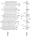
- the wire link belt (1) shown in detail in FIGS. (1) and (2) has a longitudinal extension in the directions of the double arrow (A) and is endless in these directions. In the transverse direction it has a certain width that is adapted to the respective requirements.
- the wire link belt (1) has a multiplicity of wire coils which are arranged next to one another in the longitudinal direction (A) and extend axially in the transverse direction - all designated by (2).
- Each wire helix is made up of head arches one after the other - designated by (3) for example - and two turn legs connecting two head arches (3) in each case - designated by (4) for example.
- H. each head bend (3) is followed by a turn leg (4) and this in turn is followed by a head bend (3).
- Two adjacent wire coils (2) overlap in the area of their adjacent head arches (3) in such a way that a channel extending in the transverse direction is formed between these head arches (3).
- This channel is filled by a plug wire - all designated (5) - with all plug wires (5) extending over the entire width of the wire link belt (1).
- the plug wires (5) lie within the head bends (3) wrapping around them.
- the plug wires (5) practically form a hinge joint between two adjacent wire coils (2).
- the special feature of the wire link belt (1) shown is that the winding legs (4) go through the interior of the wire link belt (1), ie change from one flat side (7) to the other flat side (8). Specifically, this means that a certain turn leg (4), after it has passed a plug wire (5) on its upper side, travels downwards and the neighboring plug wire (5) in the area wraps around the lower flat side (8). This results in a winding shape in the manner of a lying figure eight, with two adjacent winding legs (4) intersecting in the interior of the wire link strip approximately in the middle between two plug wires (5). This has the consequence that the bending stiffness between two plug wires (5) is significantly reduced and therefore the wire link belt (1) can nestle better against guide rollers.
- the interior of the wire link belt (1) between the plug wires (5) by wire material of the wire helices (2) is substantially filled, whereby the air permeability is reduced and the air volume carried with the wire link belt (1) is significantly reduced.
- the wire helices (2) are identical to one another, that is, they have the same direction of screw rotation, ie only one type of wire helix (2) is required to produce the wire link belt (1).
- the wire helices (2) themselves consist of a flat wire which is rectangular in cross section. The larger extension in the plane of the wire link belt (1) and the smaller extension are aligned transversely to this plane. Polyester or polyamides are particularly suitable as materials.
- the wire link belt (11) shown in Figures (3) and (4) also has a large number of wire helices - all designated (12) - which are arranged in the longitudinal direction - double arrow (B) - next to each other and from head arches - for example Designated (13) - and these connecting winding legs - exemplified with (14) - exist.
- the wire helices (12) overlap in the area of their head bends and form - like in the exemplary embodiment according to FIGS. (1) and (2) - channels for coupling wires, which are plug-in wires (15) which extend transversely to the longitudinal direction (B). These plug wires (15) also form hinges between two adjacent wire coils (12). In this case, a head bend (13) of a wire coil (12) alternates with a head bend (13) other wire coil (12).
- the winding legs (14) of the wire helices (12) have a course in this embodiment in which they alternate between two head bends (13) twice between the flat sides (17, 18) of the wire link belt (11), i. H. a specific winding leg (14), which begins after a head bend (13) in the area of the upper flat side (17), goes obliquely down through the interior of the wire link belt (11) to the lower flat side (18) and then up again to the upper flat side (17) until it merges into the subsequent header (13). The course is then reversed for the respectively adjacent winding leg (14).
- this wire link belt (11) too - as can be seen from the figures (3) and (4) - there is a lot of wire material inside, which reduces the air permeability and the air volume carried. Compared to the example shown in Figures (1) and (2), this wire link belt (11) is somewhat stiffer because of the reduced number of coupling plug wires (15). However, since there are two crossing points of the winding legs (14) between the coupling plug wires (15), this wire link belt (11) is also still very flexible and conforms well to guide rollers.
- FIGS. (5) and (6) show a further exemplary embodiment of the invention, namely a wire link belt (21), which extends in the longitudinal direction according to the double arrow (C) endlessly, while it has a defined width transversely to it.
- the wire link belt (21) has a multiplicity of wire coils which follow one another in the longitudinal direction (C) - all designated (22) - and extend axially in the transverse direction.
- the wire coils (22) have head bends - designated by (23) by way of example - and winding legs connecting them in each case - designated by (24) by way of example -.
- the wire helices (22) overlap in the area of their head bends (23), alternately a head bend (23) of the one wire helix (22) and a head bend (23) of the adjacent wire helix (22). In the overlap area, they each loop around a coupling plug wire - all designated (25) - so that a hinge-like joint is created there.
- the course of a particular winding leg (24) which runs obliquely upwards in the illustration according to FIG passed the non-coupling plug wire (26) on the underside.
- the respective turn leg (24) runs up through the interior of the wire link belt (21) and merges into the right-hand head bend (23) in the area of the upper flat side (27).
- the next turn leg (24), which in turn adjoins this head arc (23) passes in a first section through the interior of the wire link belt (21) from the lower flat side (28) to the upper flat side (27) and crosses the non-coupling plug wire (26 ) at the top.
- the winding leg (24) then remains in a second section Area of the upper flat side (27) and then finally merges into a left-hand header (23).
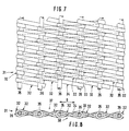
- the wire link belt (31) shown in FIGS. (7) and (8) has a longitudinal extent indicated by the double arrow (D) and a defined width running transversely thereto. At first it is very similar to the wire link belt (11) shown in Figures (3) and (4), but the main difference is that the individual wire coils overlap more strongly here.
- the wire link belt (31) has a multiplicity of wire helices joined together in the longitudinal direction (D) - all designated (32) -, the axes of which run in the width direction and the individual turns of which consist of head arches (33) and respective winding legs (34) connecting them.
- Plug wires - all designated (35) - are provided at regular intervals, which extend transversely to the longitudinal direction (D) over the entire width of the wire link belt (31).
- the overlap of two adjacent wire coils (32) is not limited to the head arches (33), but extends in each case to approximately half the length of a winding leg (34). , d. H. the overlap is approximately 50 ⁇ %.
- Two adjacent wire coils (32) therefore have not only one common plug wire (35), but two each.
- the head bend (33) of a first wire helix (32) alternates with a winding leg (34) of the second wire helix (32) immediately adjacent in the longitudinal direction (D) and a head bend (33 ) from a third wire coil (32) immediately adjacent to the second wire coil (32) in the longitudinal direction (D).
- the relevant plug wire (35) thus has a coupling function for the first and third wire helix (32) and a pure guiding function for the winding leg (34) of the second wire helix (32).
- a winding leg (34) does not differ from that in the exemplary embodiment according to FIGS. (3) and (4), i. H. a winding leg (34) adjoining a left-hand head bend (33) on the upper flat side (37) goes through the interior of the wire link belt (31) to the lower flat side (38) and crosses the plug wire (35) on the underside thereof. Then it goes up again to the upper flat side (37) and there into a right-hand header (33).
- the subsequent winding leg (34) runs in reverse, d. H. it begins on the lower flat side (38), crosses the wire link belt (31), passes the adjacent plug wire (35) on its upper side and then goes back to the lower flat side (38).
- the flexibility is limited in the wire link belt (31) shown.
- the air permeability is extraordinarily low due to the density of the intersecting winding legs (34) and the air volume that is also transported, without special measures such as the arrangement of filling materials being required for this.
Landscapes
- Engineering & Computer Science (AREA)
- Textile Engineering (AREA)
- Mechanical Engineering (AREA)
- Wire Processing (AREA)
- Paper (AREA)
- Led Devices (AREA)
- Coils Of Transformers For General Uses (AREA)
- Insulating Bodies (AREA)
- Decoration Of Textiles (AREA)
- Package Frames And Binding Bands (AREA)
- Materials For Medical Uses (AREA)
- Resistance Heating (AREA)
- Organic Insulating Materials (AREA)
- Prostheses (AREA)
- Ropes Or Cables (AREA)
- Blinds (AREA)
- Control Of Throttle Valves Provided In The Intake System Or In The Exhaust System (AREA)
- Stringed Musical Instruments (AREA)
- Supports For Plants (AREA)
Applications Claiming Priority (2)
| Application Number | Priority Date | Filing Date | Title |
|---|---|---|---|
| DE4122805A DE4122805C1 (de) | 1991-07-10 | 1991-07-10 | Drahtgliederband |
| DE4122805 | 1991-07-10 |
Publications (2)
| Publication Number | Publication Date |
|---|---|
| EP0524478A1 EP0524478A1 (de) | 1993-01-27 |
| EP0524478B1 true EP0524478B1 (de) | 1995-11-22 |
Family
ID=6435820
Family Applications (1)
| Application Number | Title | Priority Date | Filing Date |
|---|---|---|---|
| EP92111474A Expired - Lifetime EP0524478B1 (de) | 1991-07-10 | 1992-07-07 | Drahtgliederband |
Country Status (9)
| Country | Link |
|---|---|
| US (1) | US5334440A (fi) |
| EP (1) | EP0524478B1 (fi) |
| AT (1) | ATE130643T1 (fi) |
| CA (1) | CA2073380C (fi) |
| DE (2) | DE4122805C1 (fi) |
| DK (1) | DK0524478T3 (fi) |
| ES (1) | ES2082285T3 (fi) |
| FI (1) | FI96126C (fi) |
| MX (1) | MX9203930A (fi) |
Cited By (1)
| Publication number | Priority date | Publication date | Assignee | Title |
|---|---|---|---|---|
| EP2199458A1 (de) | 2008-12-22 | 2010-06-23 | Helmbach GmbH & Co.KG | Formiersieb |
Families Citing this family (13)
| Publication number | Priority date | Publication date | Assignee | Title |
|---|---|---|---|---|
| DE4403501A1 (de) * | 1994-02-04 | 1995-08-10 | Siteg Siebtech Gmbh | Spiralgliederband niedriger Luftdurchlässigkeit und Verfahren zu seiner Herstellung |
| US6202833B1 (en) | 1997-02-20 | 2001-03-20 | Wire Belt Company Of America | Conveyor belt with variable spacing |
| US5950807A (en) * | 1997-02-20 | 1999-09-14 | Wire Belt Company Of America | Wire belt with variable spacing and method of making |
| US5908106A (en) * | 1997-07-29 | 1999-06-01 | Wire Belt Company Of America | Wire belt splice edge connector |
| JP2001336048A (ja) * | 2000-05-25 | 2001-12-07 | Nobuhiko Katsura | 螺旋線材を使用した網体 |
| WO2004094275A1 (en) * | 2003-04-17 | 2004-11-04 | Cambridge International, Inc. | Plastic woven spiral conveyor belt |
| KR100439417B1 (ko) * | 2003-06-17 | 2004-07-09 | 허수영 | 개비온 단위체와 이것을 포함한 개비온 철망 |
| US20050124247A1 (en) * | 2003-11-24 | 2005-06-09 | Billings Alan L. | Metal spiral fabrics for corrugator machines |
| US7360642B2 (en) * | 2006-03-30 | 2008-04-22 | Albany International Corp. | Spiral-link belt with drive bars |
| US10689796B2 (en) * | 2013-03-14 | 2020-06-23 | Albany International Corp. | Infinity shape coil for spiral seams |
| US10689807B2 (en) * | 2013-03-14 | 2020-06-23 | Albany International Corp. | Industrial fabrics comprising infinity shape coils |
| US20230066967A1 (en) | 2020-01-31 | 2023-03-02 | Kimberly-Clark Worldwide, Inc. | Methods of adhering fused deposition modeling 3d printed elements on fabrics |
| CN112726263B (zh) * | 2020-12-23 | 2023-04-28 | 浙江华丰纸业科技有限公司 | 一种用于造纸机干燥部的聚酯植绒干网 |
Citations (1)
| Publication number | Priority date | Publication date | Assignee | Title |
|---|---|---|---|---|
| DE2419751A1 (de) * | 1974-04-24 | 1975-12-04 | Kerber Hella | Flaechige gebilde als drahtgliedergurt |
Family Cites Families (18)
| Publication number | Priority date | Publication date | Assignee | Title |
|---|---|---|---|---|
| US2276099A (en) * | 1939-02-21 | 1942-03-10 | Audubon Wire Cloth Corp | Wire fabric belt structure |
| US3202387A (en) * | 1963-12-06 | 1965-08-24 | Cambridge Wire Cloth | Woven wire conveyor belt |
| US3920117A (en) * | 1974-04-23 | 1975-11-18 | Ashworth Bros Inc | Wire conveyor belt |
| AR207603A1 (es) * | 1974-11-16 | 1976-10-15 | Friedrichs Dieter | Tejido de filtro |
| NZ193441A (en) * | 1979-04-21 | 1983-11-30 | Scapa Porritt Ltd | Link conveyor formed from plurality of helical coils |
| DE3015229A1 (de) * | 1980-04-21 | 1981-10-22 | Draadindustrie Jonge Poerink B.V., Borne | Foerderband aus draht |
| DE3039873C2 (de) * | 1980-10-22 | 1986-02-06 | Siteg Siebtechnik GmbH, 4422 Ahaus | Verfahren zum Herstellen eines mit Füllmaterial versehenen Siebbandes |
| DE3147115A1 (de) * | 1981-11-27 | 1983-06-01 | Hermann Wangner Gmbh & Co Kg, 7410 Reutlingen | Spiralgliederband und verfahren zu dessen herstellung |
| DE3243513A1 (de) * | 1982-11-25 | 1984-05-30 | Volkswagenwerk Ag | Antriebsanordnung fuer ein kraftfahrzeug |
| DE3304459A1 (de) * | 1983-02-09 | 1984-08-16 | Siteg Siebtechnik GmbH, 4422 Ahaus | Doppelspirale, verfahren zu deren herstellung, verwendung der doppelspirale zur herstellung eines siebbandes und aus diesen doppelspiralen hergestelltes spiralband |
| JPH0227467B2 (ja) * | 1983-05-28 | 1990-06-18 | Daiwa Spinning Co Ltd | Orimonojokozotai |
| US4490925A (en) * | 1983-06-08 | 1985-01-01 | Wangner Systems Corporation | Low permeability spiral fabric and method |
| US4755420A (en) * | 1984-05-01 | 1988-07-05 | Jwi Ltd. | Dryer fabric having warp strands made of melt-extrudable polyphenylene sulphide |
| US4579771A (en) * | 1984-08-10 | 1986-04-01 | Asten Group, Inc. | Laminated spiral mesh papermakers fabric |
| US4601942A (en) * | 1984-08-10 | 1986-07-22 | Asten Group Inc. | Laminated soft faced-spiral woven papermakers fabric |
| US4939025A (en) * | 1989-02-01 | 1990-07-03 | The Orr Felt Company | Papermaker's felt with flex joint seam for pin |
| DE3914534C1 (fi) * | 1989-05-02 | 1990-10-18 | Thomas Josef Heimbach Gmbh & Co, 5160 Dueren, De | |
| DE4031212A1 (de) * | 1990-10-04 | 1992-04-09 | Kufferath Geb Gkd | Drahtgewebeband |
-
1991
- 1991-07-10 DE DE4122805A patent/DE4122805C1/de not_active Expired - Fee Related
-
1992
- 1992-07-03 MX MX9203930A patent/MX9203930A/es not_active IP Right Cessation
- 1992-07-07 DE DE59204407T patent/DE59204407D1/de not_active Expired - Fee Related
- 1992-07-07 EP EP92111474A patent/EP0524478B1/de not_active Expired - Lifetime
- 1992-07-07 ES ES92111474T patent/ES2082285T3/es not_active Expired - Lifetime
- 1992-07-07 AT AT92111474T patent/ATE130643T1/de not_active IP Right Cessation
- 1992-07-07 DK DK92111474.0T patent/DK0524478T3/da active
- 1992-07-08 FI FI923146A patent/FI96126C/fi not_active IP Right Cessation
- 1992-07-09 CA CA002073380A patent/CA2073380C/en not_active Expired - Fee Related
- 1992-07-09 US US07/910,820 patent/US5334440A/en not_active Expired - Lifetime
Patent Citations (1)
| Publication number | Priority date | Publication date | Assignee | Title |
|---|---|---|---|---|
| DE2419751A1 (de) * | 1974-04-24 | 1975-12-04 | Kerber Hella | Flaechige gebilde als drahtgliedergurt |
Cited By (1)
| Publication number | Priority date | Publication date | Assignee | Title |
|---|---|---|---|---|
| EP2199458A1 (de) | 2008-12-22 | 2010-06-23 | Helmbach GmbH & Co.KG | Formiersieb |
Also Published As
| Publication number | Publication date |
|---|---|
| MX9203930A (es) | 1993-01-01 |
| CA2073380C (en) | 2004-08-10 |
| US5334440A (en) | 1994-08-02 |
| DK0524478T3 (da) | 1995-12-27 |
| ES2082285T3 (es) | 1996-03-16 |
| FI923146A (fi) | 1993-01-11 |
| FI923146A0 (fi) | 1992-07-08 |
| ATE130643T1 (de) | 1995-12-15 |
| DE59204407D1 (de) | 1996-01-04 |
| CA2073380A1 (en) | 1993-01-11 |
| EP0524478A1 (de) | 1993-01-27 |
| FI96126C (fi) | 1996-05-10 |
| DE4122805C1 (de) | 1994-10-06 |
| FI96126B (fi) | 1996-01-31 |
Similar Documents
| Publication | Publication Date | Title |
|---|---|---|
| EP0524478B1 (de) | Drahtgliederband | |
| DE3607613C2 (de) | Spiralsaumkonstruktion | |
| EP0050374B1 (de) | Verfahren zur Herstellung eines Siebbandes aus gefüllten Kunststoffspiralen und danach hergestelltes Siebband | |
| EP1035251B1 (de) | Entwässerungsband für Papiermaschinen | |
| EP1085120B1 (de) | Band für den Umlauf in Maschinen | |
| EP0472072B1 (de) | Drahtgliederband | |
| CH648878A5 (de) | Verfahren zur herstellung eines gliederbandes und dadurch hergestelltes gliederband. | |
| EP0261488B1 (de) | Maschinenfilz sowie Verfahren zur Herstellung desselben | |
| EP0017722A1 (de) | Siebband aus thermofixierbaren Kunststoffwendeln und Verfahren zu dessen Herstellung | |
| DE3914533C2 (fi) | ||
| EP1054097B1 (de) | Papiermaschinenbespannung, insbesondere als Trockensieb | |
| EP0947627B2 (de) | Maschinenfilz sowie Verfahren zu dessen Herstellung | |
| DE2938221A1 (de) | Siebband aus thermofixierbaren kunststoffwendeln und verfahren zu dessen herstellung | |
| EP0116894A1 (de) | Verfahren zur Herstellung eines Spiralbandes | |
| EP0112432B1 (de) | Flächengebilde, vorzugsweise Siebband bzw. Gliederband für Papiermaschinen o.dgl. | |
| DE3416234A1 (de) | Papiermaschinenbespannung | |
| DE3735709C2 (de) | Papiermaschinenband | |
| DE19534486C1 (de) | Gliederband insbesondere für Papiermaschinen | |
| EP0054745B1 (de) | Flächiges Gliederband | |
| EP2729611B1 (de) | Thermisch unfixiertes flächengebilde für ein spiralsieb und verfahren zum herstellen eines spiralsiebes | |
| EP1452639A1 (de) | Papiermaschinenbespannung | |
| DE102007055761A1 (de) | Spiralgliederband | |
| DE3511166A1 (de) | Spiralgliederband mit verminderter luftdurchlaessigkeit und verfahren zu dessen herstellung | |
| DE2338263C2 (de) | Vorrichtung für das Aneinanderfügen von Riemen oder Bändern | |
| DE102007047880A1 (de) | Papiermaschinenbespannung |
Legal Events
| Date | Code | Title | Description |
|---|---|---|---|
| PUAI | Public reference made under article 153(3) epc to a published international application that has entered the european phase |
Free format text: ORIGINAL CODE: 0009012 |
|
| AK | Designated contracting states |
Kind code of ref document: A1 Designated state(s): AT BE CH DE DK ES FR GB IT LI NL SE |
|
| 17P | Request for examination filed |
Effective date: 19921209 |
|
| 17Q | First examination report despatched |
Effective date: 19940901 |
|
| GRAA | (expected) grant |
Free format text: ORIGINAL CODE: 0009210 |
|
| AK | Designated contracting states |
Kind code of ref document: B1 Designated state(s): AT BE CH DE DK ES FR GB IT LI NL SE |
|
| PG25 | Lapsed in a contracting state [announced via postgrant information from national office to epo] |
Ref country code: BE Effective date: 19951122 |
|
| REF | Corresponds to: |
Ref document number: 130643 Country of ref document: AT Date of ref document: 19951215 Kind code of ref document: T |
|
| ET | Fr: translation filed | ||
| REG | Reference to a national code |
Ref country code: DK Ref legal event code: T3 |
|
| REF | Corresponds to: |
Ref document number: 59204407 Country of ref document: DE Date of ref document: 19960104 |
|
| GBT | Gb: translation of ep patent filed (gb section 77(6)(a)/1977) |
Effective date: 19960109 |
|
| ITF | It: translation for a ep patent filed |
Owner name: JACOBACCI & PERANI S.P.A. |
|
| REG | Reference to a national code |
Ref country code: ES Ref legal event code: FG2A Ref document number: 2082285 Country of ref document: ES Kind code of ref document: T3 |
|
| PLBE | No opposition filed within time limit |
Free format text: ORIGINAL CODE: 0009261 |
|
| STAA | Information on the status of an ep patent application or granted ep patent |
Free format text: STATUS: NO OPPOSITION FILED WITHIN TIME LIMIT |
|
| 26N | No opposition filed | ||
| PGFP | Annual fee paid to national office [announced via postgrant information from national office to epo] |
Ref country code: SE Payment date: 19970722 Year of fee payment: 6 |
|
| PGFP | Annual fee paid to national office [announced via postgrant information from national office to epo] |
Ref country code: DK Payment date: 19970725 Year of fee payment: 6 |
|
| PGFP | Annual fee paid to national office [announced via postgrant information from national office to epo] |
Ref country code: CH Payment date: 19970730 Year of fee payment: 6 |
|
| PG25 | Lapsed in a contracting state [announced via postgrant information from national office to epo] |
Ref country code: SE Free format text: LAPSE BECAUSE OF NON-PAYMENT OF DUE FEES Effective date: 19980708 |
|
| PG25 | Lapsed in a contracting state [announced via postgrant information from national office to epo] |
Ref country code: DK Free format text: LAPSE BECAUSE OF NON-PAYMENT OF DUE FEES Effective date: 19980731 Ref country code: CH Free format text: LAPSE BECAUSE OF NON-PAYMENT OF DUE FEES Effective date: 19980731 Ref country code: LI Free format text: LAPSE BECAUSE OF NON-PAYMENT OF DUE FEES Effective date: 19980731 |
|
| REG | Reference to a national code |
Ref country code: CH Ref legal event code: PL |
|
| EUG | Se: european patent has lapsed |
Ref document number: 92111474.0 |
|
| REG | Reference to a national code |
Ref country code: DK Ref legal event code: EBP |
|
| REG | Reference to a national code |
Ref country code: GB Ref legal event code: IF02 |
|
| PG25 | Lapsed in a contracting state [announced via postgrant information from national office to epo] |
Ref country code: IT Free format text: LAPSE BECAUSE OF NON-PAYMENT OF DUE FEES;WARNING: LAPSES OF ITALIAN PATENTS WITH EFFECTIVE DATE BEFORE 2007 MAY HAVE OCCURRED AT ANY TIME BEFORE 2007. THE CORRECT EFFECTIVE DATE MAY BE DIFFERENT FROM THE ONE RECORDED. Effective date: 20050707 |
|
| PGFP | Annual fee paid to national office [announced via postgrant information from national office to epo] |
Ref country code: AT Payment date: 20070723 Year of fee payment: 16 |
|
| PGFP | Annual fee paid to national office [announced via postgrant information from national office to epo] |
Ref country code: NL Payment date: 20070717 Year of fee payment: 16 |
|
| PGFP | Annual fee paid to national office [announced via postgrant information from national office to epo] |
Ref country code: FR Payment date: 20070718 Year of fee payment: 16 |
|
| NLV4 | Nl: lapsed or anulled due to non-payment of the annual fee |
Effective date: 20090201 |
|
| PG25 | Lapsed in a contracting state [announced via postgrant information from national office to epo] |
Ref country code: AT Free format text: LAPSE BECAUSE OF NON-PAYMENT OF DUE FEES Effective date: 20080707 |
|
| REG | Reference to a national code |
Ref country code: FR Ref legal event code: ST Effective date: 20090331 |
|
| PG25 | Lapsed in a contracting state [announced via postgrant information from national office to epo] |
Ref country code: NL Free format text: LAPSE BECAUSE OF NON-PAYMENT OF DUE FEES Effective date: 20090201 |
|
| PG25 | Lapsed in a contracting state [announced via postgrant information from national office to epo] |
Ref country code: FR Free format text: LAPSE BECAUSE OF NON-PAYMENT OF DUE FEES Effective date: 20080731 |
|
| PGFP | Annual fee paid to national office [announced via postgrant information from national office to epo] |
Ref country code: ES Payment date: 20090724 Year of fee payment: 18 |
|
| PGFP | Annual fee paid to national office [announced via postgrant information from national office to epo] |
Ref country code: DE Payment date: 20090502 Year of fee payment: 18 Ref country code: GB Payment date: 20090724 Year of fee payment: 18 |
|
| PGFP | Annual fee paid to national office [announced via postgrant information from national office to epo] |
Ref country code: BE Payment date: 20090728 Year of fee payment: 18 |
|
| BERE | Be: lapsed |
Owner name: THOMAS JOSEF *HEIMBACH G.M.B.H. & CO. Effective date: 20100731 |
|
| GBPC | Gb: european patent ceased through non-payment of renewal fee |
Effective date: 20100707 |
|
| PG25 | Lapsed in a contracting state [announced via postgrant information from national office to epo] |
Ref country code: DE Free format text: LAPSE BECAUSE OF NON-PAYMENT OF DUE FEES Effective date: 20110201 |
|
| REG | Reference to a national code |
Ref country code: DE Ref legal event code: R119 Ref document number: 59204407 Country of ref document: DE Effective date: 20110201 |
|
| PG25 | Lapsed in a contracting state [announced via postgrant information from national office to epo] |
Ref country code: BE Effective date: 20100731 |
|
| PG25 | Lapsed in a contracting state [announced via postgrant information from national office to epo] |
Ref country code: GB Free format text: LAPSE BECAUSE OF NON-PAYMENT OF DUE FEES Effective date: 20100707 |
|
| REG | Reference to a national code |
Ref country code: ES Ref legal event code: FD2A Effective date: 20110818 |
|
| PG25 | Lapsed in a contracting state [announced via postgrant information from national office to epo] |
Ref country code: ES Free format text: LAPSE BECAUSE OF NON-PAYMENT OF DUE FEES Effective date: 20100708 |