EP0522336B1 - Pelton-Laufrad und dessen Herstellung - Google Patents
Pelton-Laufrad und dessen Herstellung Download PDFInfo
- Publication number
- EP0522336B1 EP0522336B1 EP92110450A EP92110450A EP0522336B1 EP 0522336 B1 EP0522336 B1 EP 0522336B1 EP 92110450 A EP92110450 A EP 92110450A EP 92110450 A EP92110450 A EP 92110450A EP 0522336 B1 EP0522336 B1 EP 0522336B1
- Authority
- EP
- European Patent Office
- Prior art keywords
- ring
- runner
- pressure
- annular space
- welded
- Prior art date
- Legal status (The legal status is an assumption and is not a legal conclusion. Google has not performed a legal analysis and makes no representation as to the accuracy of the status listed.)
- Expired - Lifetime
Links
Images
Classifications
-
- F—MECHANICAL ENGINEERING; LIGHTING; HEATING; WEAPONS; BLASTING
- F03—MACHINES OR ENGINES FOR LIQUIDS; WIND, SPRING, OR WEIGHT MOTORS; PRODUCING MECHANICAL POWER OR A REACTIVE PROPULSIVE THRUST, NOT OTHERWISE PROVIDED FOR
- F03B—MACHINES OR ENGINES FOR LIQUIDS
- F03B1/00—Engines of impulse type, i.e. turbines with jets of high-velocity liquid impinging on blades or like rotors, e.g. Pelton wheels; Parts or details peculiar thereto
- F03B1/02—Buckets; Bucket-carrying rotors
-
- Y—GENERAL TAGGING OF NEW TECHNOLOGICAL DEVELOPMENTS; GENERAL TAGGING OF CROSS-SECTIONAL TECHNOLOGIES SPANNING OVER SEVERAL SECTIONS OF THE IPC; TECHNICAL SUBJECTS COVERED BY FORMER USPC CROSS-REFERENCE ART COLLECTIONS [XRACs] AND DIGESTS
- Y02—TECHNOLOGIES OR APPLICATIONS FOR MITIGATION OR ADAPTATION AGAINST CLIMATE CHANGE
- Y02E—REDUCTION OF GREENHOUSE GAS [GHG] EMISSIONS, RELATED TO ENERGY GENERATION, TRANSMISSION OR DISTRIBUTION
- Y02E10/00—Energy generation through renewable energy sources
- Y02E10/20—Hydro energy
-
- Y—GENERAL TAGGING OF NEW TECHNOLOGICAL DEVELOPMENTS; GENERAL TAGGING OF CROSS-SECTIONAL TECHNOLOGIES SPANNING OVER SEVERAL SECTIONS OF THE IPC; TECHNICAL SUBJECTS COVERED BY FORMER USPC CROSS-REFERENCE ART COLLECTIONS [XRACs] AND DIGESTS
- Y02—TECHNOLOGIES OR APPLICATIONS FOR MITIGATION OR ADAPTATION AGAINST CLIMATE CHANGE
- Y02P—CLIMATE CHANGE MITIGATION TECHNOLOGIES IN THE PRODUCTION OR PROCESSING OF GOODS
- Y02P70/00—Climate change mitigation technologies in the production process for final industrial or consumer products
- Y02P70/50—Manufacturing or production processes characterised by the final manufactured product
Definitions
- the invention relates to an impeller of a Pelton water turbine with a plurality of cups arranged on the outer edge of a wheel disk, and to a method for its production.
- the impellers of such Pelton turbines are today mostly manufactured as integral cast parts from a suitable cast steel and then brought into the intended shape by material removal.
- the invention has for its object to eliminate the disadvantages of the prior art and to create a Pelton impeller which can be produced with less work, which avoids critical material stresses due to a cheaper internal stress build-up and which has improved non-destructive testability after completion of the impeller and a safety-related monitoring to detect fatigue damage and to avoid wheel breaks.
- this object is achieved in that the individual cups are welded at their roots to form an annular ring and the inside of the ring is welded to the outside edge of the wheel disk with ring-shaped weld seams, two ring-shaped weld seams being provided side by side in the axial direction, which seal one Form a toroidal annular space on the outer edge of the wheel disc.
- the rim is advantageously built up from the cup roots inwards by shaping build-up welding to the position of the weld seams with the outer edge of the wheel disc.
- a closed toroidal annular space is formed by the two annular weld seams arranged next to one another in the axial direction on the ring connecting the cup roots or on the outer edge of the wheel disc.
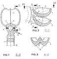
- the impeller of a Pelton water turbine shown in the figures consists of a wheel disc 1 which is rotatable about an axis of rotation X and which carries a plurality of cup-shaped blades 3 on its outer edge.
- the blades 3 are provided as double cups with a central cutting edge 11 and stiff back ribs 12, the central cutting edges 11 having a fillet 10 at the root area of the blades.
- the impeller is made in a welded construction in several steps.
- the individually produced cup-shaped blades 3 are welded together at their roots with weld seams to form a wreath.
- a ring 2 is then successively built up by shaping build-up welding and shaped to the final shape by applying a number of layers to the inside, corresponding to the outer surface of the wheel disc 1, which can be designed as a cast steel part.
- the blade ring 2 is now welded with its inner side with circular seams 4 to the outer side of the wheel disc 1 and assembled to the finished impeller.
- annular cavity 5 created by the welded construction can be used for safety-related monitoring and for early signaling of fatigue damage in the impeller.
- the breakage of the cups which occasionally occurs with previously known Pelton wheels and which as a rule cause major damage with life-threatening risk can be prevented with great certainty.
- the annular cavity 5 is filled with a suitable fluid, e.g. Liquid, gas, steam or air with a pressure different from the outside atmosphere, e.g. filled with a passive corrosion, not too viscous liquid and pressurized. Then the room is closed pressure-tight with a screw 8. The pressure p in the cavity can be monitored with a sensor 9 integrated in the screw 8. If the pressure drops due to a leak due to a crack, an emergency signal is triggered and the machine is switched off. Experience is used to this end that a leak due to fatigue cracks can be expected before a final break. Such fine fatigue cracks can be signaled continuously in the manner described during operation by the pressure drop occurring. The location of the fatigue crack can be easily located by pumping liquid into the cavity 5. It is advantageous to use a colored liquid.
- a suitable fluid e.g. Liquid, gas, steam or air with a pressure different from the outside atmosphere, e.g. filled with a passive corrosion, not too viscous liquid and pressurized.
- a cable can be led from the pressure sensor 9 from the wheel to the shaft to the bearing point. From there, contactless signal transmission is easy to implement.
- the cavity 5 can also be placed under vacuum or partial vacuum instead of under excess pressure.
- the negative pressure p is monitored by the pressure sensor 9 and an emergency signal is triggered if the vacuum is impaired.
- the advantage in both cases is that the impeller can be continuously monitored with great certainty during operation by means of a single signal. This can significantly increase the short inspection intervals that are otherwise required, so that the maintenance costs and downtimes of the hydropower plant equipped with such a monitored impeller can be considerably reduced.
- the advantage of the closed cavity 5 for crack monitoring can also be used by build-up welding, regardless of the manufacturing method of the blade ring 2 described.
Landscapes
- Engineering & Computer Science (AREA)
- Chemical & Material Sciences (AREA)
- Combustion & Propulsion (AREA)
- Mechanical Engineering (AREA)
- General Engineering & Computer Science (AREA)
- Turbine Rotor Nozzle Sealing (AREA)
- Hydraulic Turbines (AREA)
- Structures Of Non-Positive Displacement Pumps (AREA)
- Glass Compositions (AREA)
- Physical Or Chemical Processes And Apparatus (AREA)
- Sorption Type Refrigeration Machines (AREA)
- Blow-Moulding Or Thermoforming Of Plastics Or The Like (AREA)
- Moulding By Coating Moulds (AREA)
- Shaping Metal By Deep-Drawing, Or The Like (AREA)
Applications Claiming Priority (2)
| Application Number | Priority Date | Filing Date | Title |
|---|---|---|---|
| CH2080/91A CH683939A5 (de) | 1991-07-12 | 1991-07-12 | Pelton-Laufrad und dessen Herstellung. |
| CH2080/91 | 1991-07-12 |
Publications (2)
| Publication Number | Publication Date |
|---|---|
| EP0522336A1 EP0522336A1 (de) | 1993-01-13 |
| EP0522336B1 true EP0522336B1 (de) | 1995-03-01 |
Family
ID=4225439
Family Applications (1)
| Application Number | Title | Priority Date | Filing Date |
|---|---|---|---|
| EP92110450A Expired - Lifetime EP0522336B1 (de) | 1991-07-12 | 1992-06-20 | Pelton-Laufrad und dessen Herstellung |
Country Status (8)
| Country | Link |
|---|---|
| EP (1) | EP0522336B1 (es) |
| JP (1) | JP2786378B2 (es) |
| AT (1) | ATE119240T1 (es) |
| CA (1) | CA2073538A1 (es) |
| CH (1) | CH683939A5 (es) |
| DE (2) | DE4127622A1 (es) |
| ES (1) | ES2069934T3 (es) |
| NO (1) | NO307008B1 (es) |
Cited By (1)
| Publication number | Priority date | Publication date | Assignee | Title |
|---|---|---|---|---|
| EP0882888A1 (de) | 1997-06-06 | 1998-12-09 | VOEST-ALPINE MACHINERY, CONSTRUCTION & ENGINEERING GESELLSCHAFT m.b.H. | Laufrad einer Pelton-Turbine |
Families Citing this family (5)
| Publication number | Priority date | Publication date | Assignee | Title |
|---|---|---|---|---|
| FR2776341B1 (fr) | 1998-03-23 | 2000-06-09 | Gec Alsthom Neyrpic | Roue de turbine et turbine de type pelton equipee d'une telle roue |
| TW442616B (en) * | 1998-06-15 | 2001-06-23 | Dinesh Patel | An improved vane system |
| GB9826728D0 (en) | 1998-12-04 | 1999-01-27 | Rolls Royce Plc | Method and apparatus for building up a workpiece by deposit welding |
| CN110449760A (zh) * | 2019-07-16 | 2019-11-15 | 浙江富春江水电设备有限公司 | 一种冲击式转轮精焊方法及结构 |
| CN112943504A (zh) * | 2021-04-13 | 2021-06-11 | 哈尔滨电机厂有限责任公司 | 一种分环制造的大型冲击式水轮机转轮 |
Family Cites Families (4)
| Publication number | Priority date | Publication date | Assignee | Title |
|---|---|---|---|---|
| FR1014783A (fr) * | 1949-04-22 | 1952-08-21 | Roue hydraulique pelton à pales fixées par des bagues emmancliées à chaud, avec suppression complète des boulons de serrage et du disque p? des pales | |
| GB715858A (en) * | 1952-06-06 | 1954-09-22 | English Electric Co Ltd | Improvements in and relating to impulse wheel runners |
| CH402774A (fr) * | 1962-07-31 | 1966-05-31 | Neyrpic Ateliers Neyret Beylie | Roue de turbine à action |
| JPS57191467A (en) * | 1981-05-19 | 1982-11-25 | Toshiba Corp | Manufacture of guide vane for water turbine |
-
1991
- 1991-07-12 CH CH2080/91A patent/CH683939A5/de not_active IP Right Cessation
- 1991-08-21 DE DE4127622A patent/DE4127622A1/de active Granted
-
1992
- 1992-06-16 NO NO922362A patent/NO307008B1/no not_active IP Right Cessation
- 1992-06-20 ES ES92110450T patent/ES2069934T3/es not_active Expired - Lifetime
- 1992-06-20 AT AT92110450T patent/ATE119240T1/de not_active IP Right Cessation
- 1992-06-20 DE DE59201514T patent/DE59201514D1/de not_active Expired - Fee Related
- 1992-06-20 EP EP92110450A patent/EP0522336B1/de not_active Expired - Lifetime
- 1992-07-02 JP JP4175724A patent/JP2786378B2/ja not_active Expired - Lifetime
- 1992-07-09 CA CA002073538A patent/CA2073538A1/en not_active Abandoned
Cited By (1)
| Publication number | Priority date | Publication date | Assignee | Title |
|---|---|---|---|---|
| EP0882888A1 (de) | 1997-06-06 | 1998-12-09 | VOEST-ALPINE MACHINERY, CONSTRUCTION & ENGINEERING GESELLSCHAFT m.b.H. | Laufrad einer Pelton-Turbine |
Also Published As
| Publication number | Publication date |
|---|---|
| CA2073538A1 (en) | 1993-01-13 |
| NO922362D0 (no) | 1992-06-16 |
| JPH06147091A (ja) | 1994-05-27 |
| DE4127622C2 (es) | 1993-05-13 |
| DE59201514D1 (de) | 1995-04-06 |
| ATE119240T1 (de) | 1995-03-15 |
| DE4127622A1 (de) | 1993-01-14 |
| EP0522336A1 (de) | 1993-01-13 |
| NO922362L (no) | 1993-01-13 |
| JP2786378B2 (ja) | 1998-08-13 |
| ES2069934T3 (es) | 1995-05-16 |
| NO307008B1 (no) | 2000-01-24 |
| CH683939A5 (de) | 1994-06-15 |
Similar Documents
| Publication | Publication Date | Title |
|---|---|---|
| DE2507695C2 (de) | Verfahren zum Auswuchten eines modularen Gasturbinentriebwerkes | |
| EP3208457B1 (de) | Peltonrad | |
| EP0522336B1 (de) | Pelton-Laufrad und dessen Herstellung | |
| DE807299C (de) | Trommellaeufer mit Schaufelkraenzen, die an Stahlscheiben befestigt sind | |
| DE60018861T2 (de) | Kühlluftzufuhrsystem für einen Rotor | |
| DE4143378C2 (de) | Pelton-Laufrad | |
| DE19803390C1 (de) | Laufrad für eine Strömungsmaschine, insbesondere für eine Francisturbine | |
| EP0846844B1 (de) | Rotorzusammenbau mit kraftschlüssig und gleichzeitig form- bzw. materialschlüssig verbundenen Rotorscheiben | |
| DE60002781T2 (de) | Nabe-Achse Verbindung | |
| US3369763A (en) | Pulpstone mounting flanges | |
| EP0586861A1 (de) | Kombiniertes Trag- und Führungslager einer vertikalachsigen Wasserkraftmaschine | |
| EP0816015A1 (de) | Verfahren und Vorrichtung zum Versorgen der Zusammenwirkzone zwischen einem Abrasivwerkzeug und einem Werkstück mit Kühlschmiermittel | |
| WO2002027189A1 (de) | Compound-reibungsvakuumpumpe | |
| DE932042C (de) | Befestigungsvorrichtung fuer radial einzusetzende Laufschaufeln von Kreiselradmaschinen, insbesondere Gas- und Dampfturbinen | |
| AT391167B (de) | Stroemungsmaschine, wie wasserturbine, pumpe oder pumpenturbine | |
| CH669429A5 (es) | ||
| WO2020146913A1 (de) | Vorrichtung und verfahren zum schälen und trennen von mehreren schlauchlagen aufweisenden hydraulikschläuchen | |
| DE102015108556A1 (de) | Turbinenanordnung | |
| DE694257C (de) | Leitschaufelkranz fuer Dampfturbinen | |
| AT380078B (de) | Peltonrad | |
| DE968046C (de) | Verfahren und Vorrichtung zum Zerschneiden von Nitrocellulose im Zustand der Suspension | |
| DE2508869A1 (de) | Mittels druckfluessigkeit betriebener hochfrequenzschwingungsruettler | |
| DE599456C (de) | Einrichtung zum Kuehlen einer Gasturbine | |
| DE698320C (de) | Elastisch abgestuetzte Scheibe fuer radial beaufschlagte Kreiselmaschinen, insbesondere Dampf- oder Gasturbinen | |
| DE19532985C2 (de) | Druckbelastetes Gehäuse |
Legal Events
| Date | Code | Title | Description |
|---|---|---|---|
| PUAI | Public reference made under article 153(3) epc to a published international application that has entered the european phase |
Free format text: ORIGINAL CODE: 0009012 |
|
| 17P | Request for examination filed |
Effective date: 19920620 |
|
| AK | Designated contracting states |
Kind code of ref document: A1 Designated state(s): AT DE ES FR IT SE |
|
| 17Q | First examination report despatched |
Effective date: 19940308 |
|
| GRAA | (expected) grant |
Free format text: ORIGINAL CODE: 0009210 |
|
| AK | Designated contracting states |
Kind code of ref document: B1 Designated state(s): AT DE ES FR IT SE |
|
| REF | Corresponds to: |
Ref document number: 119240 Country of ref document: AT Date of ref document: 19950315 Kind code of ref document: T |
|
| REF | Corresponds to: |
Ref document number: 59201514 Country of ref document: DE Date of ref document: 19950406 |
|
| ITF | It: translation for a ep patent filed |
Owner name: ING. ZINI MARANESI & C. S.R.L. |
|
| REG | Reference to a national code |
Ref country code: ES Ref legal event code: FG2A Ref document number: 2069934 Country of ref document: ES Kind code of ref document: T3 |
|
| ET | Fr: translation filed | ||
| PLBE | No opposition filed within time limit |
Free format text: ORIGINAL CODE: 0009261 |
|
| STAA | Information on the status of an ep patent application or granted ep patent |
Free format text: STATUS: NO OPPOSITION FILED WITHIN TIME LIMIT |
|
| 26N | No opposition filed | ||
| PG25 | Lapsed in a contracting state [announced via postgrant information from national office to epo] |
Ref country code: DE Effective date: 19960301 |
|
| PGFP | Annual fee paid to national office [announced via postgrant information from national office to epo] |
Ref country code: AT Payment date: 20000523 Year of fee payment: 9 |
|
| PGFP | Annual fee paid to national office [announced via postgrant information from national office to epo] |
Ref country code: SE Payment date: 20000526 Year of fee payment: 9 |
|
| PGFP | Annual fee paid to national office [announced via postgrant information from national office to epo] |
Ref country code: FR Payment date: 20000529 Year of fee payment: 9 |
|
| PGFP | Annual fee paid to national office [announced via postgrant information from national office to epo] |
Ref country code: ES Payment date: 20000622 Year of fee payment: 9 |
|
| PG25 | Lapsed in a contracting state [announced via postgrant information from national office to epo] |
Ref country code: AT Free format text: LAPSE BECAUSE OF NON-PAYMENT OF DUE FEES Effective date: 20010620 |
|
| PG25 | Lapsed in a contracting state [announced via postgrant information from national office to epo] |
Ref country code: SE Free format text: LAPSE BECAUSE OF NON-PAYMENT OF DUE FEES Effective date: 20010621 Ref country code: ES Free format text: LAPSE BECAUSE OF NON-PAYMENT OF DUE FEES Effective date: 20010621 |
|
| EUG | Se: european patent has lapsed |
Ref document number: 92110450.1 |
|
| PG25 | Lapsed in a contracting state [announced via postgrant information from national office to epo] |
Ref country code: FR Free format text: LAPSE BECAUSE OF NON-PAYMENT OF DUE FEES Effective date: 20020228 |
|
| REG | Reference to a national code |
Ref country code: ES Ref legal event code: FD2A Effective date: 20030203 |
|
| PG25 | Lapsed in a contracting state [announced via postgrant information from national office to epo] |
Ref country code: IT Free format text: LAPSE BECAUSE OF NON-PAYMENT OF DUE FEES;WARNING: LAPSES OF ITALIAN PATENTS WITH EFFECTIVE DATE BEFORE 2007 MAY HAVE OCCURRED AT ANY TIME BEFORE 2007. THE CORRECT EFFECTIVE DATE MAY BE DIFFERENT FROM THE ONE RECORDED. Effective date: 20050620 |