EP0521180B1 - Dispositifs de signalisation des risques en boucle - Google Patents
Dispositifs de signalisation des risques en boucle Download PDFInfo
- Publication number
- EP0521180B1 EP0521180B1 EP91110973A EP91110973A EP0521180B1 EP 0521180 B1 EP0521180 B1 EP 0521180B1 EP 91110973 A EP91110973 A EP 91110973A EP 91110973 A EP91110973 A EP 91110973A EP 0521180 B1 EP0521180 B1 EP 0521180B1
- Authority
- EP
- European Patent Office
- Prior art keywords
- line
- loop
- alarm
- primary
- lines
- Prior art date
- Legal status (The legal status is an assumption and is not a legal conclusion. Google has not performed a legal analysis and makes no representation as to the accuracy of the status listed.)
- Expired - Lifetime
Links
Images

Classifications
-
- G—PHYSICS
- G08—SIGNALLING
- G08B—SIGNALLING OR CALLING SYSTEMS; ORDER TELEGRAPHS; ALARM SYSTEMS
- G08B26/00—Alarm systems in which substations are interrogated in succession by a central station
- G08B26/001—Alarm systems in which substations are interrogated in succession by a central station with individual interrogation of substations connected in parallel
Definitions
- the invention relates to a hazard detection system for loop operation with a message center to which a plurality of primary signal lines with respective hazard detectors are connected by means of a respective line interface unit.
- Hazard detectors and sensors are usually connected to the control center via a two-wire primary signal line, generally as a branch line.
- a large number of such detectors or sensors or elements are connected to such a double wire, via which they are both supplied with energy and the information flow is handled.
- Such a stub usually ends with the last element.
- a line fault e.g. in the event of a wire break or a short circuit
- the signal line is faulty and, depending on the design of the elements, the elements or at least some of them can no longer be queried.
- loop systems have several disadvantages compared to stub lines.
- the primary signal line loop which typically runs hundreds of meters through buildings and open spaces, also acts as an undesirable antenna for electromagnetic influences, which can result in high interference currents flowing through the loop, which can significantly impair the communication between the elements and the control center .
- the primary reporting line can even be totally disturbed, so that no data transmission is possible.
- such loop arrangements are often operated from one side only in uninterrupted operation like a conventional stub line, which means that all elements are interrogated from the beginning of the line to the end.
- the loop end is returned to the control center, but is then not operational there.
- the return line is then only used in the event of a fault or possibly for test purposes, i.e. in this case the line is queried from the other end.
- the loop connection element has a control and control unit which, if necessary, by means of a line switch, the relevant primary reporting line via an associated terminating element, which is also arranged in the loop connecting element and for monitoring the line section between the loop connecting element SAE and the last element En of a primary reporting line MPL is used to connect to the primary reporting return line and thus to the control center.
- the line switch is opened in the trouble-free operation.
- all primary reporting lines can be connected to the central alarm system via the primary reporting line.
- a plurality of loop interface elements can also be provided, with either each loop interface element being connected to the control center with its own primary primary return line, or the loop interface elements being connected in cascade fashion, so that only the first loop interface element with the center is connected via a single one Primary return line is connected.
- This arrangement according to the invention has proven to be expedient for hazard alarm systems which operate according to the chain synchronization principle, because the individual elements each have a switching element in one of the two-wire lines, at least for one interrogation direction.
- a primary signal line is shown as a stub line.
- the signaling primary line MPL is connected to the control center Z as a two-wire line a, b via the line interface unit LAE.
- the hazard detectors or elements E1 to En are located on the primary signal line. If a fault ST now occurs, as shown in FIG. 2, for example as a line break between element E4 and element E5, elements E5 to En can no longer be queried . In this case, these elements could be queried if the reporting primary line were switched into a loop, as shown in FIG. 3.
- the primary signal line MPL is connected at the beginning to the central station Z via a first line interface unit LAE1.
- the last element En is looped back to the central station Z and its end e is connected via a second line connection unit LAE2.
- elements E5 to En can be queried from the end e of the primary signal line MPL, that is, from the central station Z via the line interface unit LAE2.
- a short-circuit KZ In the event of a short-circuit KZ, whether it has occurred on the signaling line or in an element, an interrogation is only possible during loop operation if special separating elements are provided between some elements, as shown in Fig. 5.
- a signaling primary line MPL1 is connected with its start (on) to a first line interface unit LAE11 and the feedback, i.e. the signal primary line MPL1 is connected at its end (e) to a second line interface unit LAE12.
- a first separating element TE1 is provided between the elements E2 and E3.
- the line short-circuit KZ is assumed between the elements E3 and E4.
- a second separating element TE2 is provided between element E4 and element E5 (not specifically shown).
- the short circuit point in the event of a short circuit KZ, the short circuit point can be switched off by means of the separating elements TE1, TE2.
- the line section between the two separating elements TE1 and TE2 is thus disconnected in the event of a short-circuit.
- the elements E1 and E2 can be operated from the beginning (on) of the primary signal line MPL1, and the elements E5 to En can be operated from the end (e) of the primary signal line MPL1. Only the two elements E3 and E4 can no longer be queried.
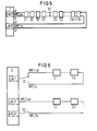
- Figure 6 shows two possible loop modes.
- the start and the end e of a primary signal line MPL1 with the elements E1 to En are connected via a first line interface unit LAE1 by means of a changeover switch S1.
- the start is at a second Signaling primary line MPL2 connected to the line interface unit LAE21.
- the loop connections are shown in simplified form with only one line. Two-wire primary signal lines with multi-pole switches are usually used. In these two cases, ie signaling primary lines MPL1 and MPL2, a separate return conductor to the control center is required from the last element En, as already mentioned. If a fault is now detected, the loop can be queried alternately from the front or from the back using the switch S1.
- the second variant known per se, is more expedient.
- the start and end of the primary signal line are routed to different line interfaces LAE21, LAE22, which may even be located on different modules.
- LAE21, LAE22 For the interrogation in loop operation from the end (e) of the primary detector line MPL2, the switch S2 is switched on. In the normal case it will be kept open for EMC reasons.
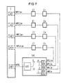
- FIG. 7 shows the loop arrangement according to the invention with a loop switching element SAE.
- the signaling primary lines MPL1 to MPLm are connected via their respective line interface units LAE1 to LAEm.
- LAE1 to LAEm the last elements En of a respective primary signal line are now routed to a loop switching element SAE, which is located at the far end of the primary signal line.
- the loop interface element SAE is only led to a central Z with a single primary signal return line MPRL and connected there via an additional line interface unit LAES.
- the loop switching element SAE has a control and control unit KSE, as well as a line switch LU and termination elements EA, the number of connection elements corresponding to the number of signaling primary lines MPL, here there are m lines shown.
- the multi-pole primary signal lines and switches are again shown in a simplified manner as simple lines.
- the line changeover switch LU is open in trouble-free operation, which is shown in FIG. 7 by the switch position zero (0). Only when a fault has been detected on one of the signaling primary lines MPL by the associated line interface unit, the line switch LU is switched to the corresponding position via the control and control device KSE and the additional line interface unit LAES, so that the faulty signal line can be operated from the line end.
- several loop connection elements SAE can be cascaded to increase the number of signaling primary lines that can be connected.
- the arrangement according to the invention with a loop switching element has a number of advantages. No hardware worth mentioning is required in the control center for loop operation. Without loop operation, all existing line interface units can be used for normal stub line operation. If loop operation is required, in addition to the loop interface element SAE, only one additional line interface unit and one primary feedback line is required for each m primary signal line. This also has the advantage that only one return line from the loop switching element, which is arranged at the far end of the many primary reporting lines, has to be returned to the central, which brings considerable cost savings, in contrast to the return of each individual primary reporting line to the central. With the arrangement according to the invention, regulations or customer requests can also be easily met if loopable systems are desired.
Claims (7)
- Système de signalisation des risques en boucle, comprenant une centrale de signalisation (Z) à laquelle sont connectées, au moyen d'une unité de connexion en ligne (LAE) respective, une pluralité de lignes de signalisation primaires (MPL1, ...) pourvues d'avertisseurs de danger respectifs (éléments E1 à En),
caractérisé en ce qu'au moins une majorité (m) des lignes de signalisation primaires (MPL1 à MPLm) arrivent, par leur extrémité éloignée (e), à un élément de connexion en boucle commun (SAE), lequel, pour sa part, est connecté à la centrale (Z) avec seulement une ligne de retour de signalisation primaire (MPRL) par l'intermédiaire d'une unité de connexion en ligne supplémentaire (LAES), et en ce que l'élément de connexion en boucle (SAE) comprend une unité de contrôle et de commande (KSE) qui, en cas de besoin, connecte la ligne de signalisation primaire concernée (MPL) à la ligne de retour de signalisation primaire (MPRL) au moyen d'un commutateur de ligne (LU) par l'intermédiaire d'un élément terminal associé (EA), le commutateur de ligne (LU)
étant ouvert en service normal. - Système de signalisation des risques selon la revendication 1, caractérisé en ce que toutes les lignes de signalisation primaires (MPL) sont connectées à l'élément de connexion en boucle (SEA).
- Système de signalisation des risques selon la revendication 1, caractérisé en ce que plusieurs éléments de connexion en boucle sont prévus.
- Système de signalisation des risques selon la revendication 3, caractérisé en ce que chaque élément de connexion en boucle est connecté à la centrale par sa propre ligne de retour de signalisation primaire.
- Système de signalisation des risques selon la revendication 3, caractérisé en ce que les éléments de connexion en boucle sont connectés en cascade, seulement le premier élément de connexion en boucle étant relié à la centrale.
- Système de signalisation des risques selon l'une des revendications précédentes, caractérisé en ce que, même en service normal, les lignes de signalisation primaires (MPL1, 2) sont surveillées régulièrement du dernier élément (En) à l'élément de connexion en boucle (SAE), ainsi que la ligne de retour de signalisation primaire (MPRL).
- Système de signalisation des risques selon l'une des revendications précédentes, caractérisé en ce que les avertisseurs de danger sont exécutés avec des éléments qui fonctionnent selon le principe de la synchronisation en chaîne.
Priority Applications (5)
| Application Number | Priority Date | Filing Date | Title |
|---|---|---|---|
| DE59108510T DE59108510D1 (de) | 1991-07-02 | 1991-07-02 | Gefahrenmeldeanlage für Schleifenbetrieb |
| ES91110973T ES2097167T3 (es) | 1991-07-02 | 1991-07-02 | Instalacion de señalizacion de peligro para funcionamiento en bucle. |
| EP91110973A EP0521180B1 (fr) | 1991-07-02 | 1991-07-02 | Dispositifs de signalisation des risques en boucle |
| AT91110973T ATE148248T1 (de) | 1991-07-02 | 1991-07-02 | Gefahrenmeldeanlage für schleifenbetrieb |
| GR970400828T GR3023171T3 (en) | 1991-07-02 | 1997-04-18 | Danger signalling devices connected in a loop |
Applications Claiming Priority (1)
| Application Number | Priority Date | Filing Date | Title |
|---|---|---|---|
| EP91110973A EP0521180B1 (fr) | 1991-07-02 | 1991-07-02 | Dispositifs de signalisation des risques en boucle |
Publications (2)
| Publication Number | Publication Date |
|---|---|
| EP0521180A1 EP0521180A1 (fr) | 1993-01-07 |
| EP0521180B1 true EP0521180B1 (fr) | 1997-01-22 |
Family
ID=8206889
Family Applications (1)
| Application Number | Title | Priority Date | Filing Date |
|---|---|---|---|
| EP91110973A Expired - Lifetime EP0521180B1 (fr) | 1991-07-02 | 1991-07-02 | Dispositifs de signalisation des risques en boucle |
Country Status (5)
| Country | Link |
|---|---|
| EP (1) | EP0521180B1 (fr) |
| AT (1) | ATE148248T1 (fr) |
| DE (1) | DE59108510D1 (fr) |
| ES (1) | ES2097167T3 (fr) |
| GR (1) | GR3023171T3 (fr) |
Family Cites Families (4)
| Publication number | Priority date | Publication date | Assignee | Title |
|---|---|---|---|---|
| DE2817089B2 (de) * | 1978-04-19 | 1980-12-18 | Siemens Ag, 1000 Berlin Und 8000 Muenchen | Gefahrenmeldeanlage |
| US4209666A (en) * | 1978-10-03 | 1980-06-24 | Lawton Richard A | Multiplexing system line fault isolation and identification |
| GB8431883D0 (en) * | 1984-12-18 | 1985-01-30 | Gent Ltd | Transmission system |
| DE3637681A1 (de) * | 1986-11-05 | 1988-05-19 | Siemens Ag | Gefahrenmeldeanlage nach dem pulsmeldesystem |
-
1991
- 1991-07-02 AT AT91110973T patent/ATE148248T1/de not_active IP Right Cessation
- 1991-07-02 EP EP91110973A patent/EP0521180B1/fr not_active Expired - Lifetime
- 1991-07-02 ES ES91110973T patent/ES2097167T3/es not_active Expired - Lifetime
- 1991-07-02 DE DE59108510T patent/DE59108510D1/de not_active Expired - Fee Related
-
1997
- 1997-04-18 GR GR970400828T patent/GR3023171T3/el unknown
Also Published As
| Publication number | Publication date |
|---|---|
| EP0521180A1 (fr) | 1993-01-07 |
| GR3023171T3 (en) | 1997-07-30 |
| DE59108510D1 (de) | 1997-03-06 |
| ES2097167T3 (es) | 1997-04-01 |
| ATE148248T1 (de) | 1997-02-15 |
Similar Documents
| Publication | Publication Date | Title |
|---|---|---|
| DE3001452A1 (de) | Alarm-, sicherungs- und ueberwachungsanlage | |
| DE2438354B2 (de) | Mehrphasige schutzanordnung fuer anlageteile elektrischer starkstromnetze | |
| EP0067339A2 (fr) | Méthode et arrangement pour détecter des perturbations dans des systèmes de signalisation de risques, en particulier signalisation d'incendie | |
| CH633917A5 (de) | Schutzschaltungsanordnung fuer elektrische anlageteile, insbesondere fuer leitungsstrecken, sammelschienen und/oder transformatoren. | |
| CH641917A5 (de) | Relaisschutzanordnung fuer ein elektrisches leitungsnetz. | |
| DE69933839T2 (de) | Verfahren und Vorrichtung zur Detektion von Leitungsshunt und Erdschlussfehler | |
| CH618801A5 (fr) | ||
| DE102011075353B4 (de) | Fehlerüberwachungssystem für eine Verteilnetzstation eines Energieversorgungsnetzes | |
| DE3805949A1 (de) | Einrichtung zur teilabschaltung einer strassenverkehrssignalanlage | |
| EP0532787B1 (fr) | Dispositif pour l'opération de détecteurs de dangers | |
| EP0175120B1 (fr) | Dispositif de protection pour un réseau électrique | |
| DE2647738A1 (de) | Fehlerortungs-verfahren und -anordnungen fuer schleifenfoermige nachrichtenuebertragungsanlagen | |
| EP0521180B1 (fr) | Dispositifs de signalisation des risques en boucle | |
| EP1197936B1 (fr) | Système d'alarme | |
| DE3637681A1 (de) | Gefahrenmeldeanlage nach dem pulsmeldesystem | |
| EP0503122B1 (fr) | Arrangement pour commuter des lignes primaires en cas de perturbations | |
| DE2711519B2 (de) | Datenübertragungs-Anlage | |
| EP0224819B1 (fr) | Système de signalisation de danger | |
| DE1562121B2 (de) | Schaltungsanordnung fuer eine koppelanordnung | |
| EP0581399B1 (fr) | Système de signalisation | |
| DE655627C (de) | Selbsttaetige Feuermeldeanlage | |
| DE19640739C1 (de) | Alarmspeicher-Schaltungsanordnung für Öffnungsmelder | |
| EP0224821A1 (fr) | Système de signalisation de dangers | |
| DE19606896A1 (de) | Schaltung zum Stellen und Überwachen von Lichtsignalen | |
| DE19747213C2 (de) | Telekommunikationssystem |
Legal Events
| Date | Code | Title | Description |
|---|---|---|---|
| PUAI | Public reference made under article 153(3) epc to a published international application that has entered the european phase |
Free format text: ORIGINAL CODE: 0009012 |
|
| AK | Designated contracting states |
Kind code of ref document: A1 Designated state(s): AT BE CH DE ES FR GB GR IT LI LU NL |
|
| 17P | Request for examination filed |
Effective date: 19930324 |
|
| 17Q | First examination report despatched |
Effective date: 19950925 |
|
| GRAG | Despatch of communication of intention to grant |
Free format text: ORIGINAL CODE: EPIDOS AGRA |
|
| GRAH | Despatch of communication of intention to grant a patent |
Free format text: ORIGINAL CODE: EPIDOS IGRA |
|
| GRAH | Despatch of communication of intention to grant a patent |
Free format text: ORIGINAL CODE: EPIDOS IGRA |
|
| GRAA | (expected) grant |
Free format text: ORIGINAL CODE: 0009210 |
|
| AK | Designated contracting states |
Kind code of ref document: B1 Designated state(s): AT BE CH DE ES FR GB GR IT LI LU NL |
|
| REF | Corresponds to: |
Ref document number: 148248 Country of ref document: AT Date of ref document: 19970215 Kind code of ref document: T |
|
| REG | Reference to a national code |
Ref country code: CH Ref legal event code: NV Representative=s name: SIEMENS SCHWEIZ AG Ref country code: CH Ref legal event code: EP |
|
| REF | Corresponds to: |
Ref document number: 59108510 Country of ref document: DE Date of ref document: 19970306 |
|
| ET | Fr: translation filed | ||
| REG | Reference to a national code |
Ref country code: ES Ref legal event code: FG2A Ref document number: 2097167 Country of ref document: ES Kind code of ref document: T3 |
|
| ITF | It: translation for a ep patent filed |
Owner name: 0508;07MIFSTUDIO JAUMANN |
|
| GBT | Gb: translation of ep patent filed (gb section 77(6)(a)/1977) |
Effective date: 19970402 |
|
| PGFP | Annual fee paid to national office [announced via postgrant information from national office to epo] |
Ref country code: GR Payment date: 19970630 Year of fee payment: 7 |
|
| REG | Reference to a national code |
Ref country code: GR Ref legal event code: FG4A Free format text: 3023171 |
|
| PGFP | Annual fee paid to national office [announced via postgrant information from national office to epo] |
Ref country code: LU Payment date: 19970915 Year of fee payment: 7 |
|
| PLBE | No opposition filed within time limit |
Free format text: ORIGINAL CODE: 0009261 |
|
| STAA | Information on the status of an ep patent application or granted ep patent |
Free format text: STATUS: NO OPPOSITION FILED WITHIN TIME LIMIT |
|
| 26N | No opposition filed | ||
| PG25 | Lapsed in a contracting state [announced via postgrant information from national office to epo] |
Ref country code: LU Free format text: LAPSE BECAUSE OF NON-PAYMENT OF DUE FEES Effective date: 19980702 |
|
| PG25 | Lapsed in a contracting state [announced via postgrant information from national office to epo] |
Ref country code: GR Free format text: LAPSE BECAUSE OF NON-PAYMENT OF DUE FEES Effective date: 19980731 |
|
| PGFP | Annual fee paid to national office [announced via postgrant information from national office to epo] |
Ref country code: DE Payment date: 20000918 Year of fee payment: 10 |
|
| PGFP | Annual fee paid to national office [announced via postgrant information from national office to epo] |
Ref country code: CH Payment date: 20001016 Year of fee payment: 10 |
|
| PGFP | Annual fee paid to national office [announced via postgrant information from national office to epo] |
Ref country code: AT Payment date: 20010620 Year of fee payment: 11 |
|
| PGFP | Annual fee paid to national office [announced via postgrant information from national office to epo] |
Ref country code: GB Payment date: 20010705 Year of fee payment: 11 |
|
| PGFP | Annual fee paid to national office [announced via postgrant information from national office to epo] |
Ref country code: NL Payment date: 20010717 Year of fee payment: 11 Ref country code: BE Payment date: 20010717 Year of fee payment: 11 |
|
| PGFP | Annual fee paid to national office [announced via postgrant information from national office to epo] |
Ref country code: ES Payment date: 20010719 Year of fee payment: 11 |
|
| PGFP | Annual fee paid to national office [announced via postgrant information from national office to epo] |
Ref country code: FR Payment date: 20010724 Year of fee payment: 11 |
|
| PG25 | Lapsed in a contracting state [announced via postgrant information from national office to epo] |
Ref country code: LI Free format text: LAPSE BECAUSE OF NON-PAYMENT OF DUE FEES Effective date: 20010731 Ref country code: CH Free format text: LAPSE BECAUSE OF NON-PAYMENT OF DUE FEES Effective date: 20010731 |
|
| REG | Reference to a national code |
Ref country code: GB Ref legal event code: IF02 |
|
| REG | Reference to a national code |
Ref country code: CH Ref legal event code: PL |
|
| PG25 | Lapsed in a contracting state [announced via postgrant information from national office to epo] |
Ref country code: DE Free format text: LAPSE BECAUSE OF NON-PAYMENT OF DUE FEES Effective date: 20020501 |
|
| PG25 | Lapsed in a contracting state [announced via postgrant information from national office to epo] |
Ref country code: GB Free format text: LAPSE BECAUSE OF NON-PAYMENT OF DUE FEES Effective date: 20020702 Ref country code: AT Free format text: LAPSE BECAUSE OF NON-PAYMENT OF DUE FEES Effective date: 20020702 |
|
| PG25 | Lapsed in a contracting state [announced via postgrant information from national office to epo] |
Ref country code: ES Free format text: LAPSE BECAUSE OF NON-PAYMENT OF DUE FEES Effective date: 20020703 |
|
| PG25 | Lapsed in a contracting state [announced via postgrant information from national office to epo] |
Ref country code: BE Free format text: LAPSE BECAUSE OF NON-PAYMENT OF DUE FEES Effective date: 20020731 |
|
| BERE | Be: lapsed |
Owner name: *SIEMENS A.G. Effective date: 20020731 |
|
| PG25 | Lapsed in a contracting state [announced via postgrant information from national office to epo] |
Ref country code: NL Free format text: LAPSE BECAUSE OF NON-PAYMENT OF DUE FEES Effective date: 20030201 |
|
| GBPC | Gb: european patent ceased through non-payment of renewal fee |
Effective date: 20020702 |
|
| PG25 | Lapsed in a contracting state [announced via postgrant information from national office to epo] |
Ref country code: FR Free format text: LAPSE BECAUSE OF NON-PAYMENT OF DUE FEES Effective date: 20030331 |
|
| NLV4 | Nl: lapsed or anulled due to non-payment of the annual fee |
Effective date: 20030201 |
|
| REG | Reference to a national code |
Ref country code: FR Ref legal event code: ST |
|
| REG | Reference to a national code |
Ref country code: ES Ref legal event code: FD2A Effective date: 20030811 |
|
| PG25 | Lapsed in a contracting state [announced via postgrant information from national office to epo] |
Ref country code: IT Free format text: LAPSE BECAUSE OF NON-PAYMENT OF DUE FEES Effective date: 20050702 |