EP0521180B1 - Danger signalling devices connected in a loop - Google Patents
Danger signalling devices connected in a loop Download PDFInfo
- Publication number
- EP0521180B1 EP0521180B1 EP91110973A EP91110973A EP0521180B1 EP 0521180 B1 EP0521180 B1 EP 0521180B1 EP 91110973 A EP91110973 A EP 91110973A EP 91110973 A EP91110973 A EP 91110973A EP 0521180 B1 EP0521180 B1 EP 0521180B1
- Authority
- EP
- European Patent Office
- Prior art keywords
- line
- loop
- alarm
- primary
- lines
- Prior art date
- Legal status (The legal status is an assumption and is not a legal conclusion. Google has not performed a legal analysis and makes no representation as to the accuracy of the status listed.)
- Expired - Lifetime
Links
Images

Classifications
-
- G—PHYSICS
- G08—SIGNALLING
- G08B—SIGNALLING OR CALLING SYSTEMS; ORDER TELEGRAPHS; ALARM SYSTEMS
- G08B26/00—Alarm systems in which substations are interrogated in succession by a central station
- G08B26/001—Alarm systems in which substations are interrogated in succession by a central station with individual interrogation of substations connected in parallel
Definitions
- the invention relates to a hazard detection system for loop operation with a message center to which a plurality of primary signal lines with respective hazard detectors are connected by means of a respective line interface unit.
- Hazard detectors and sensors are usually connected to the control center via a two-wire primary signal line, generally as a branch line.
- a large number of such detectors or sensors or elements are connected to such a double wire, via which they are both supplied with energy and the information flow is handled.
- Such a stub usually ends with the last element.
- a line fault e.g. in the event of a wire break or a short circuit
- the signal line is faulty and, depending on the design of the elements, the elements or at least some of them can no longer be queried.
- loop systems have several disadvantages compared to stub lines.
- the primary signal line loop which typically runs hundreds of meters through buildings and open spaces, also acts as an undesirable antenna for electromagnetic influences, which can result in high interference currents flowing through the loop, which can significantly impair the communication between the elements and the control center .
- the primary reporting line can even be totally disturbed, so that no data transmission is possible.
- such loop arrangements are often operated from one side only in uninterrupted operation like a conventional stub line, which means that all elements are interrogated from the beginning of the line to the end.
- the loop end is returned to the control center, but is then not operational there.
- the return line is then only used in the event of a fault or possibly for test purposes, i.e. in this case the line is queried from the other end.
- the loop connection element has a control and control unit which, if necessary, by means of a line switch, the relevant primary reporting line via an associated terminating element, which is also arranged in the loop connecting element and for monitoring the line section between the loop connecting element SAE and the last element En of a primary reporting line MPL is used to connect to the primary reporting return line and thus to the control center.
- the line switch is opened in the trouble-free operation.
- all primary reporting lines can be connected to the central alarm system via the primary reporting line.
- a plurality of loop interface elements can also be provided, with either each loop interface element being connected to the control center with its own primary primary return line, or the loop interface elements being connected in cascade fashion, so that only the first loop interface element with the center is connected via a single one Primary return line is connected.
- This arrangement according to the invention has proven to be expedient for hazard alarm systems which operate according to the chain synchronization principle, because the individual elements each have a switching element in one of the two-wire lines, at least for one interrogation direction.
- a primary signal line is shown as a stub line.
- the signaling primary line MPL is connected to the control center Z as a two-wire line a, b via the line interface unit LAE.
- the hazard detectors or elements E1 to En are located on the primary signal line. If a fault ST now occurs, as shown in FIG. 2, for example as a line break between element E4 and element E5, elements E5 to En can no longer be queried . In this case, these elements could be queried if the reporting primary line were switched into a loop, as shown in FIG. 3.
- the primary signal line MPL is connected at the beginning to the central station Z via a first line interface unit LAE1.
- the last element En is looped back to the central station Z and its end e is connected via a second line connection unit LAE2.
- elements E5 to En can be queried from the end e of the primary signal line MPL, that is, from the central station Z via the line interface unit LAE2.
- a short-circuit KZ In the event of a short-circuit KZ, whether it has occurred on the signaling line or in an element, an interrogation is only possible during loop operation if special separating elements are provided between some elements, as shown in Fig. 5.
- a signaling primary line MPL1 is connected with its start (on) to a first line interface unit LAE11 and the feedback, i.e. the signal primary line MPL1 is connected at its end (e) to a second line interface unit LAE12.
- a first separating element TE1 is provided between the elements E2 and E3.
- the line short-circuit KZ is assumed between the elements E3 and E4.
- a second separating element TE2 is provided between element E4 and element E5 (not specifically shown).
- the short circuit point in the event of a short circuit KZ, the short circuit point can be switched off by means of the separating elements TE1, TE2.
- the line section between the two separating elements TE1 and TE2 is thus disconnected in the event of a short-circuit.
- the elements E1 and E2 can be operated from the beginning (on) of the primary signal line MPL1, and the elements E5 to En can be operated from the end (e) of the primary signal line MPL1. Only the two elements E3 and E4 can no longer be queried.
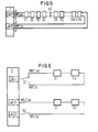
- Figure 6 shows two possible loop modes.
- the start and the end e of a primary signal line MPL1 with the elements E1 to En are connected via a first line interface unit LAE1 by means of a changeover switch S1.
- the start is at a second Signaling primary line MPL2 connected to the line interface unit LAE21.
- the loop connections are shown in simplified form with only one line. Two-wire primary signal lines with multi-pole switches are usually used. In these two cases, ie signaling primary lines MPL1 and MPL2, a separate return conductor to the control center is required from the last element En, as already mentioned. If a fault is now detected, the loop can be queried alternately from the front or from the back using the switch S1.
- the second variant known per se, is more expedient.
- the start and end of the primary signal line are routed to different line interfaces LAE21, LAE22, which may even be located on different modules.
- LAE21, LAE22 For the interrogation in loop operation from the end (e) of the primary detector line MPL2, the switch S2 is switched on. In the normal case it will be kept open for EMC reasons.
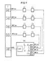
- FIG. 7 shows the loop arrangement according to the invention with a loop switching element SAE.
- the signaling primary lines MPL1 to MPLm are connected via their respective line interface units LAE1 to LAEm.
- LAE1 to LAEm the last elements En of a respective primary signal line are now routed to a loop switching element SAE, which is located at the far end of the primary signal line.
- the loop interface element SAE is only led to a central Z with a single primary signal return line MPRL and connected there via an additional line interface unit LAES.
- the loop switching element SAE has a control and control unit KSE, as well as a line switch LU and termination elements EA, the number of connection elements corresponding to the number of signaling primary lines MPL, here there are m lines shown.
- the multi-pole primary signal lines and switches are again shown in a simplified manner as simple lines.
- the line changeover switch LU is open in trouble-free operation, which is shown in FIG. 7 by the switch position zero (0). Only when a fault has been detected on one of the signaling primary lines MPL by the associated line interface unit, the line switch LU is switched to the corresponding position via the control and control device KSE and the additional line interface unit LAES, so that the faulty signal line can be operated from the line end.
- several loop connection elements SAE can be cascaded to increase the number of signaling primary lines that can be connected.
- the arrangement according to the invention with a loop switching element has a number of advantages. No hardware worth mentioning is required in the control center for loop operation. Without loop operation, all existing line interface units can be used for normal stub line operation. If loop operation is required, in addition to the loop interface element SAE, only one additional line interface unit and one primary feedback line is required for each m primary signal line. This also has the advantage that only one return line from the loop switching element, which is arranged at the far end of the many primary reporting lines, has to be returned to the central, which brings considerable cost savings, in contrast to the return of each individual primary reporting line to the central. With the arrangement according to the invention, regulations or customer requests can also be easily met if loopable systems are desired.
Abstract
Description
Die Erfindung bezieht sich auf eine Gefahrenmeldeanlage für Schleifenbetrieb mit einer Meldezentrale, an die mittels einer jeweiligen Linienanschalteinheit eine Vielzahl von Meldeprimärleitungen mit jeweiligen Gefahrenmeldern angeschlossen ist.The invention relates to a hazard detection system for loop operation with a message center to which a plurality of primary signal lines with respective hazard detectors are connected by means of a respective line interface unit.
Gefahrenmelder und -sensoren, z.B. für die Brand- oder Einbruchdetektion, werden üblicherweise über eine zweiadrige Meldeprimärleitung mit der Zentrale, im allgemeinen als Stichleitung, verbunden. Dabei ist eine Vielzahl derartiger Melder oder Sensoren bzw. Elemente an eine derartige Doppelader angeschlossen, über die sie sowohl mit Energie versorgt werden als auch der Informationsfluß abgewickelt wird. Eine solche Stichleitung endet üblicherweise mit dem letzten Element. Dabei ist jedoch von Nachteil, daß bei einem Leitungsfehler, z.B. bei einem Drahtbruch oder einem Kurzschluß, die Meldeleitung gestört ist und je nach Ausgestaltung der Elemente die Elemente oder zumindest ein Teil nicht mehr abgefragt werden können.Hazard detectors and sensors, e.g. for fire or intrusion detection, are usually connected to the control center via a two-wire primary signal line, generally as a branch line. A large number of such detectors or sensors or elements are connected to such a double wire, via which they are both supplied with energy and the information flow is handled. Such a stub usually ends with the last element. However, it is disadvantageous that in the event of a line fault, e.g. in the event of a wire break or a short circuit, the signal line is faulty and, depending on the design of the elements, the elements or at least some of them can no longer be queried.
Um dennoch eine gestörte Meldeprimärleitung betreiben zu können, schließt man derartige Leitungen in Form einer Schleife an die Zentrale, so daß im Schleifenbetrieb von der anderen Seite her die Meldeprimärleitung bis zu der Störung abgefragt werden kann und die einzelnen Elemente noch ihre Daten zur Zentrale abgeben können. Auch im Schleifenbetrieb ist der Kurzschluß ein kritischer Fall, so daß hier schon vorgeschlagen wurde, mit Hilfe von Meßeinrichtungen den Kurzschluß zu lokalisieren und auf den Linien Vorrichtungen vorzusehen, um dann die Kurzschlußstelle zu isolieren.In order to still be able to operate a faulty primary signal line, such lines are connected in a loop to the control center, so that the primary signal line can be queried from the other side up to the fault in loop operation and the individual elements can still deliver their data to the control center . The short circuit is also a critical case in loop operation, so here it is It has been proposed to locate the short circuit with the aid of measuring devices and to provide devices on the lines in order then to isolate the short circuit point.
Derartige Schleifensysteme haben gegenüber Stichleitungen mehrere Nachteile. Die Meldeprimärleitungsschleife, die in der Regel über hunderte von Metern durch Gebäude und Freigelände verläuft, wirkt gleichzeitig als unerwünschte Antenne für elektromagnetische Einflüsse, die dazu führen, daß hohe Störströme über die Schleife fließen können, die die Nachrichtenübertragung zwischen den Elementen und der Zentrale erheblich beeinträchtigen. Im Extremfall kann die Meldeprimärleitung sogar total gestört sein, so daß keine Datenübertragung möglich ist. Um dies zu vermeiden, werden solche Schleifenanordnungen im ungestörten Betrieb häufig wie eine herkömmliche Stichleitung nur von einer Seite her betrieben, das bedeutet, daß alle Elemente vom Leitungsanfang her bis zum Ende abgefragt werden. Das Schleifenende ist zur Zentrale zurückgeführt, ist aber dann dort betriebsmäßig nicht aufgeschaltet. Die Rückleitung wird also dann nur im Störungsfall oder evtl. für Prüfzwecke benützt, d.h. in diesem Fall wird vom anderen Ende her die Leitung abgefragt.Such loop systems have several disadvantages compared to stub lines. The primary signal line loop, which typically runs hundreds of meters through buildings and open spaces, also acts as an undesirable antenna for electromagnetic influences, which can result in high interference currents flowing through the loop, which can significantly impair the communication between the elements and the control center . In extreme cases, the primary reporting line can even be totally disturbed, so that no data transmission is possible. In order to avoid this, such loop arrangements are often operated from one side only in uninterrupted operation like a conventional stub line, which means that all elements are interrogated from the beginning of the line to the end. The loop end is returned to the control center, but is then not operational there. The return line is then only used in the event of a fault or possibly for test purposes, i.e. in this case the line is queried from the other end.
Es wurde auch schon vorgeschlagen, Meldeprimärleitungen im Schleifenbetrieb abwechselnd von Anfang bzw. vom Ende her abzufragen und hierbei einen Umschalter vorzusehen, wobei nur eine Linienabfrageeinheit für eine Schleife erforderlich ist, wie dies beispielsweise in der DE 36 37 681-A1 beschrieben ist.Aus ausfall-strategischen Gründen ist es jedoch zweckmäßig, den Anfang und das Ende einer Meldeprimärleitungsschleife auf unterschiedliche Linienanschalteinheiten zu führen, wobei das Ende aus EMV-Gründen über einen eigenen Schalter abtrennbar ist.It has also been proposed to alternately scan primary signal lines in loop operation from the beginning or from the end and to provide a changeover switch, only one line interrogation unit being required for a loop, as is described, for example, in DE 36 37 681-A1 For strategic reasons, however, it is advisable to route the beginning and end of a primary signal line loop to different line interface units, the end being separable via a separate switch for EMC reasons.
Bei all den bisher bekannten Anordnungen für Schleifenbetrieb ist jedoch immer der große Nachteil gegeben, daß vom letzten Element einer jeweiligen Meldeprimärleitung eine jeweilige Leitung zur Zentrale zurückgeführt werden muß, was bei einer Vielzahl von Meldeprimärleitungen und bei weit von der Zentrale entfernten Enden zu einem erheblichen zusätzlichen Installationsaufwand führt.In all of the previously known arrangements for loop operation, however, there is always the great disadvantage that a respective line must be returned from the last element of a respective primary signal line to the control center, which in the case of a large number of primary signal lines and at far ends from the control center results in a considerable additional Installation effort leads.
Aufgabe der Erfindung ist es daher, bei einer Gefahrenmeldeanlage den Schleifenbetrieb zu verbessern, den Installationsaufwand zu verringern und die Störungseinflüsse, die insbesondere durch den Schleifenbetrieb gegeben sind, zu reduzieren.It is therefore the object of the invention to improve the loop operation in a hazard detection system, to reduce the installation effort and to reduce the interference effects which are in particular caused by the loop operation.
Diese Aufgabe wird bei einer Gefahrenmeldeanlage für Schleifenbetrieb der eingangs genannten Art dadurch gelöst, daß das jeweilige Ende zumindest einer Mehrzahl von Meldeprimärleitungen an ihrem fernen Ende auf ein Schleifenanschlußelement geführt ist, welches seinerseits mit nur einer Meldeprimär-Rückleitung über eine zusätzliche Linienanschalteinheit an der Zentrale angeschlossen ist.This object is achieved in a hazard detection system for loop operation of the type mentioned at the outset in that the respective end of at least a plurality of primary signal lines is led at its distal end to a loop connecting element which, in turn, is connected to the control center with only one primary signal return line via an additional line interface unit is.
Mit dieser erfindungsgemäßen Anordnung mit nur einem Schleifenanschaltelement und einer einzigen Meldeprimär-Rückleitung für eine große Anzahl von Meldeprimärleitungen ist ein erheblich geringerer Installationsaufwand verbunden. Auf diese Weise können auch bestehende Gefahrenmeldeanlagen, die ursprünglich nur für Stichleitungen ausgelegt worden sind, falls es der Betreiber wünscht oder bestehende Vorschriften es verlangen, nachträglich für den Schleifenbetrieb umgerüstet werden. Darüberhinaus ergibt sich auch der große Vorteil bei bestehenden Anlagen, daß nur eine geringe Hardware-Leistung erforderlich ist, jedoch die Zentrale programmäßig in einfacherer Weise umgerüstet werden kann.With this arrangement according to the invention with only one loop connection element and a single primary signal return line for a large number of primary signal lines, considerably less installation effort is involved. In this way, existing hazard detection systems, which were originally only designed for branch lines, if the operator wishes it or existing regulations require it, can be retrofitted for loop operation. In addition, there is also the great advantage in existing systems that only a low hardware performance is required, but the control center can be converted in a simpler manner in terms of program.
In einer zweckmäßigen Ausgestaltung weist das Schleifenanschaltelement eine Kontroll- und Steuereinheit auf, welche im Bedarfsfall mittels eines Leitungsumschalters die betreffende Meldeprimärleitung über ein zugehöriges Abschlußelement, welches ebenfalls im Schleifenanschlußelement angeordnet ist und zur Überwachung des Leitungsstückes zwischen Schleifenanschlußelement SAE und dem jeweils letzten Element En einer Meldeprimärleitung MPL dient, an die Meldeprimär-Rückleitung und damit an die Zentrale anschaltet. In vorteilhafter Weise ist dabei im störungsfreien Betrieb der Leitungsumschalter geöffnet.In an expedient embodiment, the loop connection element has a control and control unit which, if necessary, by means of a line switch, the relevant primary reporting line via an associated terminating element, which is also arranged in the loop connecting element and for monitoring the line section between the loop connecting element SAE and the last element En of a primary reporting line MPL is used to connect to the primary reporting return line and thus to the control center. Advantageously, the line switch is opened in the trouble-free operation.
Mit Hilfe des Schleifenanschaltelementes können dabei sämtliche Meldeprimärleitungen über die Meldeprimärleitung an der Gefahrenmeldezentrale angeschlossen werden. In einer besonderen Ausgestaltung der Erfindung können aber auch mehrere Schleifenanschaltelemente vorgesehen sein, wobei entweder jedes Schleifenanschaltelement mit einer eigenen Meldeprimär-Rückleitung an der Zentrale angeschlossen ist, oder aber die Schleifenanschaltelemente kaskadenförmig angeschlossen sind, so daß lediglich das erste Schleifenanschaltelement mit der Zentrale über eine einzige Meldeprimär-Rückleitung verbunden ist.With the help of the loop switching element, all primary reporting lines can be connected to the central alarm system via the primary reporting line. In a special embodiment of the invention, however, a plurality of loop interface elements can also be provided, with either each loop interface element being connected to the control center with its own primary primary return line, or the loop interface elements being connected in cascade fashion, so that only the first loop interface element with the center is connected via a single one Primary return line is connected.
Mit dieser Anordnung ist es möglich, auch im störungsfreien Betrieb die Meldeprimärleitungen vom letzten Element zum Schleifenanschaltelement und die Meldeprimärrückleitung regelmäßig zu überwachen.With this arrangement it is possible to regularly monitor the primary signal lines from the last element to the loop switching element and the primary signal return line even in the case of trouble-free operation.
Diese erfindungsgemäße Anordnung hat sich als zweckmäßig für Gefahrenmeldeanlagen, die nach dem Kettensynchronisationsprinzip arbeiten, erwiesen, weil die einzelnen Elemente zumindest für eine Abfragerichtung jeweils ein Durchschalteelement in einer der zweiadrigen Leitungen aufweisen.This arrangement according to the invention has proven to be expedient for hazard alarm systems which operate according to the chain synchronization principle, because the individual elements each have a switching element in one of the two-wire lines, at least for one interrogation direction.
Im folgenden wird die Erfindung anhand einer Zeichnung näher erläutert. Dabei zeigen
- Fig. 1 eine Meldeprimärleitung als Stichleitung im ungestörten Betrieb,
- Fig. 2 eine Meldeprimärleitung als Stichleitung im gestörten Betrieb,
- Fig. 3 eine Meldeprimärleitung als Schleife im ungestörten Betrieb,
- Fig. 4 eine Meldeprimärleitung als Schleife im gestörten Betrieb,
- Fig. 5 eine bekannte Schleifenanordnung mit Trennelementen für den Kurzschlußfall,
- Fig. 6 mögliche Schleifenbetriebsarten wie sie bereits ebenfalls vorgeschlagen wurden und
- Fig. 7 die erfindungsgemäße Schleifenanordnung mit einem Schleifenanschaltelement.
- 1 shows a primary signal line as a branch line in undisturbed operation,
- 2 shows a primary signal line as a stub line in disturbed operation,
- 3 shows a primary signal line as a loop in undisturbed operation,
- 4 shows a primary signal line as a loop in the disturbed operation,
- 5 shows a known loop arrangement with separating elements for a short circuit,
- Fig. 6 possible loop modes as they have also been proposed and
- 7 shows the loop arrangement according to the invention with a loop switching element.
In Fig. 1 und 2 ist Eine Meldeprimärleitung als Stichleitung dargestellt. An der Zentrale Z ist über die Linienanschalteinheit LAE die Meldeprimärleitung MPL als zweiadrige Leitung a,b angeschlossen. Auf der Meldeprimärleitung befinden sich die Gefahrenmelder bzw. -elemente E1 bis En. Tritt nun wie in Fig. 2 dargestellt eine Störung ST, beispielsweise als Leitungsunterbrechung zwischen dem Element E4 und dem Element E5 auf, so sind die Elemente E5 bis En nicht mehr abfragbar. In diesem Fall wären diese Elemente abfragbar, wenn die Meldeprimärleitung zu einer Schleife geschaltet wäre, wie dies in Fig.3 gezeigt ist.1 and 2, a primary signal line is shown as a stub line. The signaling primary line MPL is connected to the control center Z as a two-wire line a, b via the line interface unit LAE. The hazard detectors or elements E1 to En are located on the primary signal line. If a fault ST now occurs, as shown in FIG. 2, for example as a line break between element E4 and element E5, elements E5 to En can no longer be queried . In this case, these elements could be queried if the reporting primary line were switched into a loop, as shown in FIG. 3.
In Fig. 3 ist die Meldeprimärleitung MPL als Anfang an an der Zentrale Z über eine erste Linienanschalteinheit LAE1 angeschlossen. Das letzte Element En ist zur Schleife zur Zentrale Z zurückgeführt und mit seinem Ende e über eine zweite Linienanschalteinheit LAE2 angeschlossen. Im vorgenannten Störungsfall ST ist dann bei vorhandenem Schleifenbetrieb, wie dies in Fig.4 dargestellt ist, ein Abfragen der Elemente E5 bis En vom Ende e der Meldeprimärleitung MPL her, also von der Zentrale Z über die Linienanschalteinheit LAE2 möglich.3, the primary signal line MPL is connected at the beginning to the central station Z via a first line interface unit LAE1. The last element En is looped back to the central station Z and its end e is connected via a second line connection unit LAE2. In the above-mentioned fault case ST, when loop operation is present, as shown in FIG. 4, elements E5 to En can be queried from the end e of the primary signal line MPL, that is, from the central station Z via the line interface unit LAE2.
Bei einem Kurzschluß KZ, sei es, daß er auf der Meldeleitung oder auch in einem Element eingetreten ist, ist eine Abfrage auch bei Schleifenbetrieb nur möglich, wenn zwischen manchen Elementen besondere Trennelemente vorgesehen sind, wie dies in Fig.5 dargestellt ist. An der Zentrale Z ist wiederum eine Meldeprimärleitung MPL1 mit ihrem Anfang (an) an einer ersten Linienanschalteinheit LAE11 angeschlossen und die Rückführung, d.h. die Meldeprimärleitung MPL1 mit ihrem Ende (e) an einer zweiten Linienanschalteinheit LAE12 angeschlossen. Zwischen den Elementen E2 und E3 ist ein erstes Trennelement TE1 vorgesehen. Zwischen dem Element E3 und E4 ist der Leitungskurzschluß KZ angenommen. Zwischen dem Element E4 und Element E5 (nicht eigens dargestellt) ist ein zweites Trennelement TE2 vorgesehen. Bei dieser bekannten Anordnung kann im Kurzschlußfall KZ die Kurzschlußstelle mittels der Trennelemente TE1, TE2 abgeschaltet werden. Das Leitungsstück zwischen den beiden Trennelementen TE1 und TE2 wird also im Kurzschlußfall KZ abgetrennt. Vom Anfang (an) der Meldeprimärleitung MPL1 her können die Elemente E1 und E2 betrieben werden, vom Ende (e) der Meldeprimärleitung MPL1 her können die Elemente E5 bis En betrieben werden. Lediglich die zwei Elemente E3 und E4 können nicht mehr abgefragt werden.In the event of a short-circuit KZ, whether it has occurred on the signaling line or in an element, an interrogation is only possible during loop operation if special separating elements are provided between some elements, as shown in Fig. 5. At the central station Z, a signaling primary line MPL1 is connected with its start (on) to a first line interface unit LAE11 and the feedback, i.e. the signal primary line MPL1 is connected at its end (e) to a second line interface unit LAE12. A first separating element TE1 is provided between the elements E2 and E3. The line short-circuit KZ is assumed between the elements E3 and E4. A second separating element TE2 is provided between element E4 and element E5 (not specifically shown). With this known arrangement, in the event of a short circuit KZ, the short circuit point can be switched off by means of the separating elements TE1, TE2. The line section between the two separating elements TE1 and TE2 is thus disconnected in the event of a short-circuit. The elements E1 and E2 can be operated from the beginning (on) of the primary signal line MPL1, and the elements E5 to En can be operated from the end (e) of the primary signal line MPL1. Only the two elements E3 and E4 can no longer be queried.
Im Bild 6 sind zwei mögliche Schleifenbetriebsarten dargestellt. An der Zentrale Z sind über eine erste Linienanschalteinheit LAE1 mittels eines Umschalters S1 der Anfang an und das Ende e einer Meldeprimärleitung MPL1 mit den Elementen E1 bis En angeschlossen. In der zweiten Variante für den Schleifenbetrieb ist der Anfang an einer zweiten Meldeprimärleitung MPL2 mit der Linienanschalteinheit LAE21 angeschlossen. Hier sind die Schleifenanschaltungen vereinfacht nur mit einer Linie dargestellt. Üblicherweise werden zweiadrige Meldeprimärleitungen mit mehrpoligen Schaltern verwendet. Bei diesen beiden Fällen, d.h. Meldeprimärleitungen MPL1 und MPL2, wird vom letzten Element En ein eigener Rückleiter zur Zentrale wie bereits gesagt benötigt. Wird nun eine Störung erkannt, kann die Schleife über den Umschalter S1 wechselweise von vorne oder von rückwärts abgefragt werden. Die hier angedeutete, an sich bekannte zweite Variante ist zweckmäßiger. Dort ist der Anfang und das Ende der Meldeprimärleitung auf unterschiedliche Linienanschaltungen LAE21, LAE22 geführt, die sich gegebenenfalls sogar auf unterschiedlichen Baugruppen befinden können. Für die Abfrage im Schleifenbetrieb von dem Ende (e) der Melderprimärleitung MPL2 her wird der Schalter S2 eingeschaltet. Im regulären Fall wird man ihn aus EMV-Gründen offenhalten.Figure 6 shows two possible loop modes. At the central station Z, the start and the end e of a primary signal line MPL1 with the elements E1 to En are connected via a first line interface unit LAE1 by means of a changeover switch S1. In the second variant for loop operation, the start is at a second Signaling primary line MPL2 connected to the line interface unit LAE21. Here, the loop connections are shown in simplified form with only one line. Two-wire primary signal lines with multi-pole switches are usually used. In these two cases, ie signaling primary lines MPL1 and MPL2, a separate return conductor to the control center is required from the last element En, as already mentioned. If a fault is now detected, the loop can be queried alternately from the front or from the back using the switch S1. The second variant, known per se, is more expedient. There, the start and end of the primary signal line are routed to different line interfaces LAE21, LAE22, which may even be located on different modules. For the interrogation in loop operation from the end (e) of the primary detector line MPL2, the switch S2 is switched on. In the normal case it will be kept open for EMC reasons.
Die Fig. 7 zeigt die erfindungsgemäße Schleifenanordnung mit einem Schleifenanschaltelement SAE. An der Zentrale Z sind mit ihrem Anfang an die Meldeprimärleitungen MPL1 bis MPLm über jeweilige Linienanschalteinheiten LAE1 bis LAEm angeschlossen. Um diesen Stichleitungen, die im Regelfall mit dem letzten Element En enden, einen Schleifenbetrieb zu ermöglichen, sind nun die letzten Elemente En einer jeweiligen Meldeprimärleitung auf ein Schleifenanschaltelement SAE geführt, welches sich am fernen Ende der Meldeprimärleitung befindet. Dies ist in der Fig.7 mit den Meldeprimärleitungen MPL1e bis MPLme dargestellt. Das Schleifenanschaltelement SAE ist lediglich mit einer einzigen Meldeprimärrückleitung MPRL zur Zentrale Z geführt und dort über eine zusätzliche Leitungsanschalteinheit LAES angeschlossen. Das Schleifenanschaltelement SAE weist vereinfacht dargestellt eine Kontroll- und Steuereinheit KSE auf, sowie einen Leitungsumschalter LU und Abschlußelemente EA, wobei die Anzahl der Anschlußelemente der Anzahl der Meldeprimärleitungen MPL entspricht, hier sind m Leitungen dargestellt. Die mehrpoligen Meldeprimärleitungen und Schalter sind in vereinfachter Weise wieder als einfache Linien dargestellt. Der Leitungsumschalter LU ist im störungsfreien Betrieb geöffnet, was in der Fig.7 durch die Schaltstellung Null (0) dargestellt ist. Erst wenn auf einer der Meldeprimärleitungen MPL durch die zugehörige Linienanschalteinheit eine Störung festgestellt wurde, wird der Leitungsschalter LU über die Kontroll- und Steuereinrichtung KSE und die zusätzliche Linienanschalteinheit LAES in die entsprechende Position geschaltet, so daß die gestörte Meldeleitung vom Leitungsende her betrieben werden kann. Gegebenfalls können auch mehrere Schleifenanschlußelemente (SAE) kaskadiert werden, um die Anzahl der anschaltbaren Meldeprimärleitungen zu vergrößern.7 shows the loop arrangement according to the invention with a loop switching element SAE. At the center Z, the signaling primary lines MPL1 to MPLm are connected via their respective line interface units LAE1 to LAEm. In order to enable these stub lines, which usually end with the last element En, to operate in a loop, the last elements En of a respective primary signal line are now routed to a loop switching element SAE, which is located at the far end of the primary signal line. This is shown in FIG. 7 with the signaling primary lines MPL1e to MPLme. The loop interface element SAE is only led to a central Z with a single primary signal return line MPRL and connected there via an additional line interface unit LAES. In a simplified representation, the loop switching element SAE has a control and control unit KSE, as well as a line switch LU and termination elements EA, the number of connection elements corresponding to the number of signaling primary lines MPL, here there are m lines shown. The multi-pole primary signal lines and switches are again shown in a simplified manner as simple lines. The line changeover switch LU is open in trouble-free operation, which is shown in FIG. 7 by the switch position zero (0). Only when a fault has been detected on one of the signaling primary lines MPL by the associated line interface unit, the line switch LU is switched to the corresponding position via the control and control device KSE and the additional line interface unit LAES, so that the faulty signal line can be operated from the line end. If necessary, several loop connection elements (SAE) can be cascaded to increase the number of signaling primary lines that can be connected.
Die erfindungsgemäße Anordnung mit einem Schleifenanschaltelement weist eine Reihe von Vorteilen auf. Für den Schleifenbetrieb ist in der Zentrale keine nennenwerte Hardware erforderlich. Ohne Schleifenbetrieb können alle vorhandenen Linienanschalteinheiten für den normalen Stichleitungsbetrieb verwendet werden. Wird Schleifenbetrieb gefordert, so ist neben dem Schleifenanschaltelement SAE für jeweils m-Meldeprimärleitungen nur eine zusätzliche Linienanschalteinheit und eine Meldeprimärrückleitung erforderlich. Das hat darüberhinaus den Vorteil, daß nur eine Rückleitung vom Schleifenanschaltelement, das am fernen Ende der vielen Meldeprimärleitungen angeordnet wird, zur Zentrale zurückgeführt werden muß, was erhebliche Kosteneinsparungen bringt, im Gegensatz zur Rückführung jeder einzelnen Meldeprimärleitung zur Zentrale. Mit der erfindungsgemäßen Anordnung können auch Vorschriften oder Kundenwünsche leicht erfüllt werden, wenn schleifenfähige Systeme gewünscht sind. Im normalen Betrieb werden dann diese erfindungsgemäß ausgestalteten Schleifensysteme wie normale Stichleitungen betrieben, weil sich in der Praxis so häufig keine Leitungsfehler zeigen. Mit der Erfindung lassen sich daher solche Anforderungen mit einem vertretbaren Kostenaufwand realisieren, ohne daß dafür große Vorleistungen nötig sind, die die große Zahl der übrigen Anlagen ohne Schleifentechnik kostenmäßig vorbelasten.The arrangement according to the invention with a loop switching element has a number of advantages. No hardware worth mentioning is required in the control center for loop operation. Without loop operation, all existing line interface units can be used for normal stub line operation. If loop operation is required, in addition to the loop interface element SAE, only one additional line interface unit and one primary feedback line is required for each m primary signal line. This also has the advantage that only one return line from the loop switching element, which is arranged at the far end of the many primary reporting lines, has to be returned to the central, which brings considerable cost savings, in contrast to the return of each individual primary reporting line to the central. With the arrangement according to the invention, regulations or customer requests can also be easily met if loopable systems are desired. In normal operation, these loop systems designed according to the invention are then operated like normal stub lines, because in practice they are so common show no line faults. With the invention, therefore, such requirements can be realized at a reasonable cost, without the need for large upfront investments, which preload the large number of other systems without loop technology.
Claims (7)
- Alarm indicating system for loop operation, having a central alarm station (Z) to which, by means of a respective line connection unit (LAE), there is connected a multiplicity of primary alarm lines (MPL1, ...) with respective alarm indicators (elements E1 to En), characterized in that at least a plurality (m) of primary alarm lines (MPL1 to MPLm) is led at its far end (e) to a common loop connection element (SAE) which, for its part, is connected using only one primary alarm return line (MPRL) via an additional line connection unit (LAES) to the central station (Z), and in that the loop connection element (SAE) has a monitoring and control unit (KSE) which, if need be, connects the relevant primary alarm line (MPL) by means of a line changeover switch (LU), via an associated termination unit (EA), to the primary alarm return line (MPRL), the line changeover switch (LU) being open during trouble-free operation.
- Alarm indicating system according to Claim 1, characterized in that all the primary alarm lines (MPL) are connected to the loop connection element (SAE).
- Alarm indicating system according to Claim 1, characterized in that a plurality of loop connection elements is provided.
- Alarm indicating system according to Claim 3, characterized in that each loop connection element is connected to the central station using its own primary alarm return line.
- Alarm indicating system according to Claim 3, characterized in that the loop connection elements are connected in cascade, only the first loop connection element being connected to the central station.
- Alarm indicating system according to one of the preceding claims, characterized in that, even in trouble-free operation, the primary alarm lines (MPL1,2) from the last element (En) to the loop connection element (SAE), and the primary alarm return line (MPRL) are regularly monitored.
- Alarm indicating system according to one of the preceding claims, characterized in that the alarm indicators are constructed using elements which operate according to the known chain synchronization principle.
Priority Applications (5)
| Application Number | Priority Date | Filing Date | Title |
|---|---|---|---|
| AT91110973T ATE148248T1 (en) | 1991-07-02 | 1991-07-02 | HAZARD ALARM SYSTEM FOR LOOP OPERATION |
| EP91110973A EP0521180B1 (en) | 1991-07-02 | 1991-07-02 | Danger signalling devices connected in a loop |
| ES91110973T ES2097167T3 (en) | 1991-07-02 | 1991-07-02 | DANGER SIGNALING INSTALLATION FOR LOOP OPERATION. |
| DE59108510T DE59108510D1 (en) | 1991-07-02 | 1991-07-02 | Hazard detection system for loop operation |
| GR970400828T GR3023171T3 (en) | 1991-07-02 | 1997-04-18 | Danger signalling devices connected in a loop |
Applications Claiming Priority (1)
| Application Number | Priority Date | Filing Date | Title |
|---|---|---|---|
| EP91110973A EP0521180B1 (en) | 1991-07-02 | 1991-07-02 | Danger signalling devices connected in a loop |
Publications (2)
| Publication Number | Publication Date |
|---|---|
| EP0521180A1 EP0521180A1 (en) | 1993-01-07 |
| EP0521180B1 true EP0521180B1 (en) | 1997-01-22 |
Family
ID=8206889
Family Applications (1)
| Application Number | Title | Priority Date | Filing Date |
|---|---|---|---|
| EP91110973A Expired - Lifetime EP0521180B1 (en) | 1991-07-02 | 1991-07-02 | Danger signalling devices connected in a loop |
Country Status (5)
| Country | Link |
|---|---|
| EP (1) | EP0521180B1 (en) |
| AT (1) | ATE148248T1 (en) |
| DE (1) | DE59108510D1 (en) |
| ES (1) | ES2097167T3 (en) |
| GR (1) | GR3023171T3 (en) |
Family Cites Families (4)
| Publication number | Priority date | Publication date | Assignee | Title |
|---|---|---|---|---|
| DE2817089B2 (en) * | 1978-04-19 | 1980-12-18 | Siemens Ag, 1000 Berlin Und 8000 Muenchen | Alarm system |
| US4209666A (en) * | 1978-10-03 | 1980-06-24 | Lawton Richard A | Multiplexing system line fault isolation and identification |
| GB8431883D0 (en) * | 1984-12-18 | 1985-01-30 | Gent Ltd | Transmission system |
| DE3637681A1 (en) * | 1986-11-05 | 1988-05-19 | Siemens Ag | Alarm signalling system according to the pulse signalling system |
-
1991
- 1991-07-02 AT AT91110973T patent/ATE148248T1/en not_active IP Right Cessation
- 1991-07-02 EP EP91110973A patent/EP0521180B1/en not_active Expired - Lifetime
- 1991-07-02 ES ES91110973T patent/ES2097167T3/en not_active Expired - Lifetime
- 1991-07-02 DE DE59108510T patent/DE59108510D1/en not_active Expired - Fee Related
-
1997
- 1997-04-18 GR GR970400828T patent/GR3023171T3/en unknown
Also Published As
| Publication number | Publication date |
|---|---|
| ATE148248T1 (en) | 1997-02-15 |
| GR3023171T3 (en) | 1997-07-30 |
| DE59108510D1 (en) | 1997-03-06 |
| EP0521180A1 (en) | 1993-01-07 |
| ES2097167T3 (en) | 1997-04-01 |
Similar Documents
| Publication | Publication Date | Title |
|---|---|---|
| DE3001452A1 (en) | ALARM, SECURING AND MONITORING SYSTEM | |
| DE2438354B2 (en) | MULTI-PHASE PROTECTION ARRANGEMENT FOR SYSTEM COMPONENTS OF ELECTRIC POWER GRIDS | |
| EP0067339A2 (en) | Method and arrangement for disturbance detection in hazard signalling systems, especially fire signalling systems | |
| CH633917A5 (en) | PROTECTIVE CIRCUIT ARRANGEMENT FOR ELECTRICAL SYSTEM PARTS, ESPECIALLY FOR CABLE LINES, BUSBARS AND / OR TRANSFORMERS. | |
| CH641917A5 (en) | RELAY PROTECTION ARRANGEMENT FOR AN ELECTRICAL CABLE NETWORK. | |
| DE69933839T2 (en) | Method and device for detecting line shunt and ground fault | |
| EP0491260A1 (en) | Wiring device | |
| CH618801A5 (en) | ||
| DE3805949A1 (en) | DEVICE FOR THE PARTIAL SHUTDOWN OF A ROAD SIGNAL SYSTEM | |
| EP0532787B1 (en) | Device for operating hazard detectors | |
| EP0175120B1 (en) | Protecting device for an electric network | |
| DE2647738A1 (en) | ERROR LOCATION PROCEDURES AND ARRANGEMENTS FOR LOOP-FORMED MESSAGE TRANSFER SYSTEMS | |
| EP0521180B1 (en) | Danger signalling devices connected in a loop | |
| EP1197936B1 (en) | Alarm system | |
| DE3337276A1 (en) | Switch panel for a medium-voltage or low-voltage switching and distribution installation | |
| DE3637681A1 (en) | Alarm signalling system according to the pulse signalling system | |
| EP0503122B1 (en) | Arrangement for commuting primary leads during faults | |
| DE2711519B2 (en) | Data transmission system | |
| EP0224819B1 (en) | Danger-signalling system | |
| DE1562121B2 (en) | CIRCUIT ARRANGEMENT FOR A COUPLING ARRANGEMENT | |
| EP0581399B1 (en) | Signaling system | |
| DE655627C (en) | Automatic fire alarm system | |
| DE19640739C1 (en) | Alarm storage circuit for intruder detection system | |
| EP0224821A1 (en) | Danger-signalling system | |
| DE19606896A1 (en) | Light signals setting and monitoring circuit, esp. for railway operations |
Legal Events
| Date | Code | Title | Description |
|---|---|---|---|
| PUAI | Public reference made under article 153(3) epc to a published international application that has entered the european phase |
Free format text: ORIGINAL CODE: 0009012 |
|
| AK | Designated contracting states |
Kind code of ref document: A1 Designated state(s): AT BE CH DE ES FR GB GR IT LI LU NL |
|
| 17P | Request for examination filed |
Effective date: 19930324 |
|
| 17Q | First examination report despatched |
Effective date: 19950925 |
|
| GRAG | Despatch of communication of intention to grant |
Free format text: ORIGINAL CODE: EPIDOS AGRA |
|
| GRAH | Despatch of communication of intention to grant a patent |
Free format text: ORIGINAL CODE: EPIDOS IGRA |
|
| GRAH | Despatch of communication of intention to grant a patent |
Free format text: ORIGINAL CODE: EPIDOS IGRA |
|
| GRAA | (expected) grant |
Free format text: ORIGINAL CODE: 0009210 |
|
| AK | Designated contracting states |
Kind code of ref document: B1 Designated state(s): AT BE CH DE ES FR GB GR IT LI LU NL |
|
| REF | Corresponds to: |
Ref document number: 148248 Country of ref document: AT Date of ref document: 19970215 Kind code of ref document: T |
|
| REG | Reference to a national code |
Ref country code: CH Ref legal event code: NV Representative=s name: SIEMENS SCHWEIZ AG Ref country code: CH Ref legal event code: EP |
|
| REF | Corresponds to: |
Ref document number: 59108510 Country of ref document: DE Date of ref document: 19970306 |
|
| ET | Fr: translation filed | ||
| REG | Reference to a national code |
Ref country code: ES Ref legal event code: FG2A Ref document number: 2097167 Country of ref document: ES Kind code of ref document: T3 |
|
| ITF | It: translation for a ep patent filed |
Owner name: 0508;07MIFSTUDIO JAUMANN |
|
| GBT | Gb: translation of ep patent filed (gb section 77(6)(a)/1977) |
Effective date: 19970402 |
|
| PGFP | Annual fee paid to national office [announced via postgrant information from national office to epo] |
Ref country code: GR Payment date: 19970630 Year of fee payment: 7 |
|
| REG | Reference to a national code |
Ref country code: GR Ref legal event code: FG4A Free format text: 3023171 |
|
| PGFP | Annual fee paid to national office [announced via postgrant information from national office to epo] |
Ref country code: LU Payment date: 19970915 Year of fee payment: 7 |
|
| PLBE | No opposition filed within time limit |
Free format text: ORIGINAL CODE: 0009261 |
|
| STAA | Information on the status of an ep patent application or granted ep patent |
Free format text: STATUS: NO OPPOSITION FILED WITHIN TIME LIMIT |
|
| 26N | No opposition filed | ||
| PG25 | Lapsed in a contracting state [announced via postgrant information from national office to epo] |
Ref country code: LU Free format text: LAPSE BECAUSE OF NON-PAYMENT OF DUE FEES Effective date: 19980702 |
|
| PG25 | Lapsed in a contracting state [announced via postgrant information from national office to epo] |
Ref country code: GR Free format text: LAPSE BECAUSE OF NON-PAYMENT OF DUE FEES Effective date: 19980731 |
|
| PGFP | Annual fee paid to national office [announced via postgrant information from national office to epo] |
Ref country code: DE Payment date: 20000918 Year of fee payment: 10 |
|
| PGFP | Annual fee paid to national office [announced via postgrant information from national office to epo] |
Ref country code: CH Payment date: 20001016 Year of fee payment: 10 |
|
| PGFP | Annual fee paid to national office [announced via postgrant information from national office to epo] |
Ref country code: AT Payment date: 20010620 Year of fee payment: 11 |
|
| PGFP | Annual fee paid to national office [announced via postgrant information from national office to epo] |
Ref country code: GB Payment date: 20010705 Year of fee payment: 11 |
|
| PGFP | Annual fee paid to national office [announced via postgrant information from national office to epo] |
Ref country code: NL Payment date: 20010717 Year of fee payment: 11 Ref country code: BE Payment date: 20010717 Year of fee payment: 11 |
|
| PGFP | Annual fee paid to national office [announced via postgrant information from national office to epo] |
Ref country code: ES Payment date: 20010719 Year of fee payment: 11 |
|
| PGFP | Annual fee paid to national office [announced via postgrant information from national office to epo] |
Ref country code: FR Payment date: 20010724 Year of fee payment: 11 |
|
| PG25 | Lapsed in a contracting state [announced via postgrant information from national office to epo] |
Ref country code: LI Free format text: LAPSE BECAUSE OF NON-PAYMENT OF DUE FEES Effective date: 20010731 Ref country code: CH Free format text: LAPSE BECAUSE OF NON-PAYMENT OF DUE FEES Effective date: 20010731 |
|
| REG | Reference to a national code |
Ref country code: GB Ref legal event code: IF02 |
|
| REG | Reference to a national code |
Ref country code: CH Ref legal event code: PL |
|
| PG25 | Lapsed in a contracting state [announced via postgrant information from national office to epo] |
Ref country code: DE Free format text: LAPSE BECAUSE OF NON-PAYMENT OF DUE FEES Effective date: 20020501 |
|
| PG25 | Lapsed in a contracting state [announced via postgrant information from national office to epo] |
Ref country code: GB Free format text: LAPSE BECAUSE OF NON-PAYMENT OF DUE FEES Effective date: 20020702 Ref country code: AT Free format text: LAPSE BECAUSE OF NON-PAYMENT OF DUE FEES Effective date: 20020702 |
|
| PG25 | Lapsed in a contracting state [announced via postgrant information from national office to epo] |
Ref country code: ES Free format text: LAPSE BECAUSE OF NON-PAYMENT OF DUE FEES Effective date: 20020703 |
|
| PG25 | Lapsed in a contracting state [announced via postgrant information from national office to epo] |
Ref country code: BE Free format text: LAPSE BECAUSE OF NON-PAYMENT OF DUE FEES Effective date: 20020731 |
|
| BERE | Be: lapsed |
Owner name: *SIEMENS A.G. Effective date: 20020731 |
|
| PG25 | Lapsed in a contracting state [announced via postgrant information from national office to epo] |
Ref country code: NL Free format text: LAPSE BECAUSE OF NON-PAYMENT OF DUE FEES Effective date: 20030201 |
|
| GBPC | Gb: european patent ceased through non-payment of renewal fee |
Effective date: 20020702 |
|
| PG25 | Lapsed in a contracting state [announced via postgrant information from national office to epo] |
Ref country code: FR Free format text: LAPSE BECAUSE OF NON-PAYMENT OF DUE FEES Effective date: 20030331 |
|
| NLV4 | Nl: lapsed or anulled due to non-payment of the annual fee |
Effective date: 20030201 |
|
| REG | Reference to a national code |
Ref country code: FR Ref legal event code: ST |
|
| REG | Reference to a national code |
Ref country code: ES Ref legal event code: FD2A Effective date: 20030811 |
|
| PG25 | Lapsed in a contracting state [announced via postgrant information from national office to epo] |
Ref country code: IT Free format text: LAPSE BECAUSE OF NON-PAYMENT OF DUE FEES Effective date: 20050702 |