EP0520544B1 - Verbesserte Vorrichtung zum Heben und Hämmern der Fundamentpfähle von Offshore-Bauwerken - Google Patents
Verbesserte Vorrichtung zum Heben und Hämmern der Fundamentpfähle von Offshore-Bauwerken Download PDFInfo
- Publication number
- EP0520544B1 EP0520544B1 EP92201713A EP92201713A EP0520544B1 EP 0520544 B1 EP0520544 B1 EP 0520544B1 EP 92201713 A EP92201713 A EP 92201713A EP 92201713 A EP92201713 A EP 92201713A EP 0520544 B1 EP0520544 B1 EP 0520544B1
- Authority
- EP
- European Patent Office
- Prior art keywords
- pile
- hammer
- support element
- electromagnet
- lifting
- Prior art date
- Legal status (The legal status is an assumption and is not a legal conclusion. Google has not performed a legal analysis and makes no representation as to the accuracy of the status listed.)
- Expired - Lifetime
Links
Images


Classifications
-
- E—FIXED CONSTRUCTIONS
- E02—HYDRAULIC ENGINEERING; FOUNDATIONS; SOIL SHIFTING
- E02D—FOUNDATIONS; EXCAVATIONS; EMBANKMENTS; UNDERGROUND OR UNDERWATER STRUCTURES
- E02D7/00—Methods or apparatus for placing sheet pile bulkheads, piles, mouldpipes, or other moulds
- E02D7/02—Placing by driving
- E02D7/06—Power-driven drivers
- E02D7/08—Drop drivers with free-falling hammer
-
- E—FIXED CONSTRUCTIONS
- E02—HYDRAULIC ENGINEERING; FOUNDATIONS; SOIL SHIFTING
- E02D—FOUNDATIONS; EXCAVATIONS; EMBANKMENTS; UNDERGROUND OR UNDERWATER STRUCTURES
- E02D7/00—Methods or apparatus for placing sheet pile bulkheads, piles, mouldpipes, or other moulds
- E02D7/28—Placing of hollow pipes or mould pipes by means arranged inside the piles or pipes
Definitions
- This invention relates to a new hammering device which allows for an effective, reliable, rapid and in particular controlled installation of foundation piles for offshore structures, by enabling the pile to be lifted and the hammering energy to be adapted to the ground characteristics, and by eliminating any danger of resonance.
- the foundation piles have to be lifted and positioned by external pile gripping clamps and cranes situated on a pontoon for offshore work, and then hammered by a pile driver which is suspended from a crane and rested on the head of the pile to be driven into the ground, and comprises a mechanically or hydraulically operated hammer.
- this known method has a series of drawbacks, of which the main one is the fact that as the pile has a considerable free length and is subjected to waves having an oscillation frequency close to that of the pile itself, dangerous resonance conditions can be produced which in addition to generating considerable stresses in the pile which can cause its undesirable deformation, also make it materially impossible to install the pile driver on the head of the oscillating pile.
- US Patent N° 3526283 discloses a pile driver to be installed and supported by the upper part of the pile. It is provided with a pneumatic or hydraulic cylinder for the lifting of the hammer and its releasing to cause it to fall on the head of the pile, causing its penetration in the soil. During the hammering, the device is rigidly associated with the pile and goes down together with the pile.
- EP-A-265566 discloses another pile driver to be installed on the head of the pile. It is provided with an electromagnetic apparatus that causes the lifting of a hammering mass by exciting a magnet coil that cause the lifting stroke of the hammer, with respect to the coil and along a hollow guide. The frequency of the excitation determines the frequency of the strikes. During the hammering, also this device is associated with the pile and goes down together with the pile.
- the object of the present invention is to obviate the aforesaid drawbacks by providing a device which has the double function of lifting the foundation pile to be driven into the sea bed and preventing any dangerous resonance of the pile.
- Said device is formed with a long support element to be inserted into the foundation pile to be driven into the sea bed, said support element being suspended from a crane situated on a pontoon for offshore work and being provided at its lower end with an expansion-type gripping clamp for said pile and at its upper end with a hammering system comprising a striking weight or hammer slidable along said support element until a limit stop present on said element is reached.
- said support element eliminates any danger of resonance by being inserted freely into the foundation pile to a length of the order of twenty metres and maintaining a constant tension within the pile which creates opposing forces to the horizontal movement of the pile head.
- the device for lifting and hammering the foundation piles of offshore structures comprising a striking weight or hammer slidable along a guide suspended from a crane situated on a pontoon for offshore work, is characterised according to the present invention in that said guide consists of a long support element to be inserted into the foundation pile to be driven into the sea bed, said element being provided at its lower end with an expansion-type gripping clamp for said pile and at its upper end with an electromagnet cooperating with said striking weight or hammer of ferrous material slidable along said support element until a limit stop present on said element is reached.
- said hammering system consists of a striking weight or hammer of ferrous material cooperating with an electromagnet fixed to the upper end of said long support element.
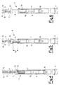
- 1 indicates a foundation pile which is to be inserted into the appropriate guide 2 of the offshore structure 3 and then driven into the sea bed 4 by hammering until a predetermined penetration is achieved.
- the lifting and hammering device 5 of the invention consisting of a long support element 6 which has to be completely inserted into said pile 1.
- Said element 6 is held suspended from a crane, not shown in the figures, situated on a pontoon for offshore work, also not shown in the figures, by a sling 7 connected to the hook 8 of said crane and shackled at 9 to the lower end of the element, where it is provided with an expansion-type gripping clamp 10 operated hydraulically from said pontoon via a hose 11.
- the support element 6 comprises, rigid therewith, an electromagnet 12 activated via the power cable 13, to cooperate with the striking weight or hammer 14 slidable along said support element 6 as far as a limit stop 15 provided on the support element 6.
- the device operates in the following manner.
- the support element 6 is then lowered until the electromagnet 12 makes contact with the striking weight 14, which is again rigidly retained by the electromagnet by energizing this latter, after which the described cycle is repeated.
Landscapes
- Engineering & Computer Science (AREA)
- Life Sciences & Earth Sciences (AREA)
- General Life Sciences & Earth Sciences (AREA)
- Mining & Mineral Resources (AREA)
- Paleontology (AREA)
- Civil Engineering (AREA)
- General Engineering & Computer Science (AREA)
- Structural Engineering (AREA)
- Placing Or Removing Of Piles Or Sheet Piles, Or Accessories Thereof (AREA)
- Load-Engaging Elements For Cranes (AREA)
- Foundations (AREA)
- Revetment (AREA)
- Conveying And Assembling Of Building Elements In Situ (AREA)
- Investigation Of Foundation Soil And Reinforcement Of Foundation Soil By Compacting Or Drainage (AREA)
- Earth Drilling (AREA)
- Types And Forms Of Lifts (AREA)
- Discharge Lamp (AREA)
- Electrophonic Musical Instruments (AREA)
Claims (3)
- Vorrichtung (5) zum Heben und Positionieren von rohrartigen Fundamentpfählen (1) für Offshore-Bauwerke (3) in eine in dem Offshore-Bauwerk vorgesehene Pfahlführung (2) und zum Hämmern derartiger Pfähle in den Meeresboden (4) mittels eines auf einem Ponton angeordneten Kranes, welche Vorrichtung ein Schlaggewicht oder einen Hammer (14) umfaßt, welcher entlang eines in den Fundamentpfahl einzusetzenden Führungselementes (6) gleitet, welches Führungselement an seinem unteren Ende eine Greifklammer (10) des ausweitbaren Typs umfaßt, um während dem Transport und dem Einsetzen des Pfahles (1) in die Pfahlführung (2) des Offshore-Bauwerkes (3) festgezogen zu werden, dadurch gekennzeichnet, daß die Vorrichtung folgende Elemente umfaßt:- ein verglichen mit der Länge des Pfahles relativ langes Supportelement (6), welches das Führungselement bildet, welches von dem Kran über ein Tragseil (7) abgehängt ist, welches Supportelement in dem Fundamentpfahl frei gleitend gehalten wird, wobei die Greifklammer (10) vom ausweitbaren Typ während dem Hammervorgang außer Eingriff gehalten ist;- den Hammer (14), der frei entlang der Außenseite des Supportelementes (6) gleitet, wobei der Hammer aus eisenhaltigem Material besteht;- einen Elektromagneten (12), welcher an dem oberen Teil des Supportelementes (6) angeordnet und starr damit verbunden ist, welcher erregt wird, um mit dem Hammer (14) an seinem oberen Bereich magnetisch zusammenzuwirken und um gemeinsam mit dem Hammer während des Hebens der gesamten Vorrichtung (5) durch das mit dem Kran verbundene Tragseil (7) bewegbar zu sein, wobei der Elektromagnet aberregt wird, wenn der Hammer (14) freigegeben werden soll, um zu bewirken, daß er mit dem Kopf des Pfahles (1) kollidiert;- einen Begrenzungsanschlag (15) in einem Zwischenbereich des Elementes (6), um den Hammer (14) zu stoppen und um den Stoß desselben zu absorbieren.
- Vorrichtung zum Hämmern von Fundamentpfählen von Offshore-Bauwerken nach Anspruch 1, dadurch gekennzeichnet, daß das Supportelement (6) weiters eine Länge in der Größenordnung von zwanzig Metern aufweist.
- Verfahren zum Heben und Hämmern von Fundamentpfählen eines Offshore-Bauwerkes mit einer Vorrichtung nach Anspruch 1, dadurch gekennzeichnet, daß es folgende Schritte umfaßt:- a) vollständiges Einsetzen der Vorrichtung (5) in den Fundamentpfahl (1);- b) Festlegen der Greifklammer (10) gegen die Innenwand des Pfahles (1), während der erregte Elektromagnet (12) den Hammer (14) hält;- c) Anheben des Pfahles (1) mit dem Kran und Positionieren desselben in der Pfahlführung (2) des Offhore-Bauwerkes (3);- d) Lösen der Klammer (10);- e) Anheben der gesamten Vorrichtung (5) mit dem Kran um eine Höhendifferenz entsprechend dem gewünschten Fallweg (16) des Hammers (14);- f) Aberregen des Elektromegneten (12), um das Fallen des Hammers zu bewirken, so daß er mit dem Kopf des Pfahles (1) kollidiert;- g) Absenken des Supportelementes (6), bis der Elektromagnet (12) neuerlich mit dem Hammer (14) in Kontakt kommt, welcher neuerlich starr durch den erregten Elektromagneten (12) gehalten wird;- h) Wiederholen der Stufen -e) bis -g), bis die vorbestimmte Eindringtiefe des Fundamentpfahles (1) erreicht ist.
Applications Claiming Priority (2)
| Application Number | Priority Date | Filing Date | Title |
|---|---|---|---|
| ITMI911793 | 1991-06-28 | ||
| ITMI911793A IT1248590B (it) | 1991-06-28 | 1991-06-28 | Dispositivo perfezionato per il sollevamento e la battitura dei pali di fondazione di strutture offshore |
Publications (2)
| Publication Number | Publication Date |
|---|---|
| EP0520544A1 EP0520544A1 (de) | 1992-12-30 |
| EP0520544B1 true EP0520544B1 (de) | 1995-08-09 |
Family
ID=11360232
Family Applications (1)
| Application Number | Title | Priority Date | Filing Date |
|---|---|---|---|
| EP92201713A Expired - Lifetime EP0520544B1 (de) | 1991-06-28 | 1992-06-12 | Verbesserte Vorrichtung zum Heben und Hämmern der Fundamentpfähle von Offshore-Bauwerken |
Country Status (14)
| Country | Link |
|---|---|
| US (1) | US5257879A (de) |
| EP (1) | EP0520544B1 (de) |
| AT (1) | ATE126303T1 (de) |
| BR (1) | BR9202482A (de) |
| CA (1) | CA2071427C (de) |
| DE (1) | DE69203980T2 (de) |
| DK (1) | DK0520544T3 (de) |
| ES (1) | ES2076665T3 (de) |
| FI (1) | FI103525B (de) |
| GR (1) | GR3017228T3 (de) |
| IE (1) | IE69030B1 (de) |
| IT (1) | IT1248590B (de) |
| NO (1) | NO304528B1 (de) |
| NZ (1) | NZ243254A (de) |
Cited By (2)
| Publication number | Priority date | Publication date | Assignee | Title |
|---|---|---|---|---|
| AU2010241465B2 (en) * | 2009-11-17 | 2011-11-24 | Bauer Maschinen Gmbh | Underwater drilling arrangement and method for introducing a tubular foundation element into the bed of a body of water |
| US8517639B2 (en) | 2005-10-14 | 2013-08-27 | Tidal Generation Limited | Installation of underwater anchorages |
Families Citing this family (7)
| Publication number | Priority date | Publication date | Assignee | Title |
|---|---|---|---|---|
| FR2723975A1 (fr) * | 1994-08-30 | 1996-03-01 | Technip Geoproduction | Plate-forme petroliere de forage ou d'exploitation en mer, pourvue de moyens perfectionnes d'ancrage dans le sol marin. |
| US7163357B1 (en) | 2001-10-02 | 2007-01-16 | Peterson James L | Method and apparatus for lifting and stabilizing subsided slabs, flatwork and foundations of buildings |
| US6814524B1 (en) | 2001-10-02 | 2004-11-09 | James L. Peterson | Method and apparatus for lifting and stabilizing subsided slabs, flatwork and foundations of buildings |
| NZ528332A (en) * | 2003-09-22 | 2006-04-28 | Ramet Holdings Ltd | Impact driver for driving poles, piles or posts including linear induction motor |
| NL2012858B1 (en) * | 2014-05-22 | 2016-03-15 | Ihc Holland Ie Bv | Tubular foundation element, assembly and method for installing tubular foundation elements in a ground formation. |
| US10941538B2 (en) * | 2018-04-13 | 2021-03-09 | Hohhot Sifang Engineering Quality Testing Center | Hammering system with electromagnetic power for dynamic pile testing |
| CN115030213B (zh) * | 2022-05-26 | 2023-04-11 | 上海勘测设计研究院有限公司 | 一种适用于海上风电基桩的工装以及应用方法 |
Family Cites Families (7)
| Publication number | Priority date | Publication date | Assignee | Title |
|---|---|---|---|---|
| US3526283A (en) * | 1968-07-23 | 1970-09-01 | S O G Research & Dev Corp | Pile driver |
| US3680644A (en) * | 1970-12-28 | 1972-08-01 | Santa Fe Int Corp | Pile driving system and apparatus |
| US4257720A (en) * | 1979-01-15 | 1981-03-24 | Pipe Technology Systems, Inc. | Apparatus and method for driving members into the ocean floor |
| US4362439A (en) * | 1981-03-02 | 1982-12-07 | Vaynkof Peter P | Hydrostatically operated underwater pile driver and method of operating same |
| FR2601397B1 (fr) * | 1986-07-11 | 1989-07-28 | Technologies Speciales Ingenie | Procede et dispositif de battage pour enfoncer des outils dans le sol. |
| DE3663967D1 (en) * | 1986-10-24 | 1989-07-20 | Procedes Tech Const | Electromagnetic percussion pile driver |
| DE3771217D1 (de) * | 1987-07-28 | 1991-08-08 | Menck Gmbh | Tauchfaehige elektrohydraulische antriebseinheit fuer zum unterwassereinsatz ausgelegte ramm- und arbeitsgeraete. |
-
1991
- 1991-06-28 IT ITMI911793A patent/IT1248590B/it active IP Right Grant
-
1992
- 1992-06-12 ES ES92201713T patent/ES2076665T3/es not_active Expired - Lifetime
- 1992-06-12 EP EP92201713A patent/EP0520544B1/de not_active Expired - Lifetime
- 1992-06-12 DK DK92201713.2T patent/DK0520544T3/da active
- 1992-06-12 AT AT92201713T patent/ATE126303T1/de not_active IP Right Cessation
- 1992-06-12 DE DE69203980T patent/DE69203980T2/de not_active Expired - Fee Related
- 1992-06-15 US US07/898,470 patent/US5257879A/en not_active Expired - Fee Related
- 1992-06-17 CA CA002071427A patent/CA2071427C/en not_active Expired - Fee Related
- 1992-06-17 NO NO922371A patent/NO304528B1/no not_active IP Right Cessation
- 1992-06-22 NZ NZ243254A patent/NZ243254A/en unknown
- 1992-06-25 FI FI922948A patent/FI103525B/fi active
- 1992-07-01 IE IE922084A patent/IE69030B1/en not_active IP Right Cessation
- 1992-07-07 BR BR929202482A patent/BR9202482A/pt not_active IP Right Cessation
-
1995
- 1995-08-30 GR GR950402336T patent/GR3017228T3/el unknown
Cited By (2)
| Publication number | Priority date | Publication date | Assignee | Title |
|---|---|---|---|---|
| US8517639B2 (en) | 2005-10-14 | 2013-08-27 | Tidal Generation Limited | Installation of underwater anchorages |
| AU2010241465B2 (en) * | 2009-11-17 | 2011-11-24 | Bauer Maschinen Gmbh | Underwater drilling arrangement and method for introducing a tubular foundation element into the bed of a body of water |
Also Published As
| Publication number | Publication date |
|---|---|
| EP0520544A1 (de) | 1992-12-30 |
| CA2071427A1 (en) | 1992-12-29 |
| NO922371D0 (no) | 1992-06-17 |
| GR3017228T3 (en) | 1995-11-30 |
| DK0520544T3 (da) | 1995-11-13 |
| DE69203980T2 (de) | 1996-02-15 |
| DE69203980D1 (de) | 1995-09-14 |
| CA2071427C (en) | 2000-02-15 |
| NO304528B1 (no) | 1999-01-04 |
| FI103525B1 (fi) | 1999-07-15 |
| FI922948A0 (fi) | 1992-06-25 |
| NO922371L (no) | 1992-12-29 |
| FI922948L (fi) | 1992-12-29 |
| IE69030B1 (en) | 1996-08-07 |
| BR9202482A (pt) | 1993-02-09 |
| IT1248590B (it) | 1995-01-19 |
| US5257879A (en) | 1993-11-02 |
| IE922084A1 (en) | 1992-12-30 |
| ITMI911793A0 (it) | 1991-06-28 |
| ITMI911793A1 (it) | 1992-12-28 |
| NZ243254A (en) | 1994-10-26 |
| ES2076665T3 (es) | 1995-11-01 |
| ATE126303T1 (de) | 1995-08-15 |
| FI103525B (fi) | 1999-07-15 |
Similar Documents
| Publication | Publication Date | Title |
|---|---|---|
| EP0520544B1 (de) | Verbesserte Vorrichtung zum Heben und Hämmern der Fundamentpfähle von Offshore-Bauwerken | |
| US20170233971A1 (en) | Foundation of an offshore structure | |
| CN108571005B (zh) | 导管架施工工艺 | |
| US5332047A (en) | Pile driving apparatus and method | |
| US3932999A (en) | Pile driving | |
| US3847231A (en) | Pole reinforcement installation | |
| JP3463035B2 (ja) | 杭の圧入及び引き抜き装置 | |
| JP6826801B2 (ja) | 漁礁及び漁礁の設置方法 | |
| CN211979216U (zh) | 一种地球物理勘探用人工震源装置 | |
| KR102627767B1 (ko) | 해양용 항타 장치 | |
| JPH0734791Y2 (ja) | 海底アンカーの形成装置 | |
| JP2991569B2 (ja) | ダブルハンマー式杭打ち装置 | |
| KR102727532B1 (ko) | 솔레노이드 구조에 의해 동작되는 항타기용 해머 | |
| USRE28151E (en) | Tube driving apparatus | |
| CN116104084B (zh) | 槽钢施工装置 | |
| JPH06346441A (ja) | 船体を用いた打込杭の打設方法及びその装置 | |
| JPH11200358A (ja) | 砂杭造成方法および同装置 | |
| CN217500201U (zh) | 锤击钢管桩施工系统 | |
| JP3683936B2 (ja) | 鋼管杭打撃工法およびその装置 | |
| RU1796742C (ru) | Устройство дл пробивки вертикальных скважин | |
| JPH073055B2 (ja) | 水中用杭打ハンマ及び水中杭打ち工法 | |
| JPS6136576Y2 (de) | ||
| AU2009274628B2 (en) | System and method for driving pile under water | |
| JP2004044199A (ja) | ジャケット構造体の施工方法及び水平調整装置 | |
| JPH04257788A (ja) | 海中条体配設装置 |
Legal Events
| Date | Code | Title | Description |
|---|---|---|---|
| PUAI | Public reference made under article 153(3) epc to a published international application that has entered the european phase |
Free format text: ORIGINAL CODE: 0009012 |
|
| AK | Designated contracting states |
Kind code of ref document: A1 Designated state(s): AT BE DE DK ES FR GB GR LU NL PT SE |
|
| 17P | Request for examination filed |
Effective date: 19930120 |
|
| 17Q | First examination report despatched |
Effective date: 19931214 |
|
| GRAA | (expected) grant |
Free format text: ORIGINAL CODE: 0009210 |
|
| AK | Designated contracting states |
Kind code of ref document: B1 Designated state(s): AT BE DE DK ES FR GB GR LU NL PT SE |
|
| REF | Corresponds to: |
Ref document number: 126303 Country of ref document: AT Date of ref document: 19950815 Kind code of ref document: T |
|
| REF | Corresponds to: |
Ref document number: 69203980 Country of ref document: DE Date of ref document: 19950914 |
|
| ET | Fr: translation filed | ||
| REG | Reference to a national code |
Ref country code: GR Ref legal event code: FG4A Free format text: 3017228 |
|
| REG | Reference to a national code |
Ref country code: ES Ref legal event code: FG2A Ref document number: 2076665 Country of ref document: ES Kind code of ref document: T3 |
|
| REG | Reference to a national code |
Ref country code: DK Ref legal event code: T3 |
|
| PLBE | No opposition filed within time limit |
Free format text: ORIGINAL CODE: 0009261 |
|
| STAA | Information on the status of an ep patent application or granted ep patent |
Free format text: STATUS: NO OPPOSITION FILED WITHIN TIME LIMIT |
|
| 26N | No opposition filed | ||
| REG | Reference to a national code |
Ref country code: GB Ref legal event code: IF02 |
|
| PGFP | Annual fee paid to national office [announced via postgrant information from national office to epo] |
Ref country code: PT Payment date: 20020529 Year of fee payment: 11 |
|
| PGFP | Annual fee paid to national office [announced via postgrant information from national office to epo] |
Ref country code: SE Payment date: 20020611 Year of fee payment: 11 |
|
| PGFP | Annual fee paid to national office [announced via postgrant information from national office to epo] |
Ref country code: AT Payment date: 20020612 Year of fee payment: 11 |
|
| PGFP | Annual fee paid to national office [announced via postgrant information from national office to epo] |
Ref country code: LU Payment date: 20020620 Year of fee payment: 11 |
|
| PGFP | Annual fee paid to national office [announced via postgrant information from national office to epo] |
Ref country code: GR Payment date: 20020626 Year of fee payment: 11 |
|
| PGFP | Annual fee paid to national office [announced via postgrant information from national office to epo] |
Ref country code: BE Payment date: 20020827 Year of fee payment: 11 |
|
| PGFP | Annual fee paid to national office [announced via postgrant information from national office to epo] |
Ref country code: FR Payment date: 20030610 Year of fee payment: 12 |
|
| PGFP | Annual fee paid to national office [announced via postgrant information from national office to epo] |
Ref country code: GB Payment date: 20030611 Year of fee payment: 12 |
|
| PG25 | Lapsed in a contracting state [announced via postgrant information from national office to epo] |
Ref country code: LU Free format text: LAPSE BECAUSE OF NON-PAYMENT OF DUE FEES Effective date: 20030612 Ref country code: AT Free format text: LAPSE BECAUSE OF NON-PAYMENT OF DUE FEES Effective date: 20030612 |
|
| PG25 | Lapsed in a contracting state [announced via postgrant information from national office to epo] |
Ref country code: SE Free format text: LAPSE BECAUSE OF NON-PAYMENT OF DUE FEES Effective date: 20030613 |
|
| PGFP | Annual fee paid to national office [announced via postgrant information from national office to epo] |
Ref country code: DK Payment date: 20030613 Year of fee payment: 12 |
|
| PGFP | Annual fee paid to national office [announced via postgrant information from national office to epo] |
Ref country code: DE Payment date: 20030618 Year of fee payment: 12 |
|
| PGFP | Annual fee paid to national office [announced via postgrant information from national office to epo] |
Ref country code: ES Payment date: 20030619 Year of fee payment: 12 |
|
| PG25 | Lapsed in a contracting state [announced via postgrant information from national office to epo] |
Ref country code: BE Free format text: LAPSE BECAUSE OF NON-PAYMENT OF DUE FEES Effective date: 20030630 |
|
| PGFP | Annual fee paid to national office [announced via postgrant information from national office to epo] |
Ref country code: NL Payment date: 20030630 Year of fee payment: 12 |
|
| BERE | Be: lapsed |
Owner name: *SAIPEM S.P.A. Effective date: 20030630 |
|
| PG25 | Lapsed in a contracting state [announced via postgrant information from national office to epo] |
Ref country code: PT Free format text: LAPSE BECAUSE OF NON-PAYMENT OF DUE FEES Effective date: 20031231 |
|
| PG25 | Lapsed in a contracting state [announced via postgrant information from national office to epo] |
Ref country code: GR Free format text: LAPSE BECAUSE OF NON-PAYMENT OF DUE FEES Effective date: 20040107 |
|
| EUG | Se: european patent has lapsed | ||
| REG | Reference to a national code |
Ref country code: PT Ref legal event code: MM4A Free format text: LAPSE DUE TO NON-PAYMENT OF FEES Effective date: 20031231 |
|
| PG25 | Lapsed in a contracting state [announced via postgrant information from national office to epo] |
Ref country code: GB Free format text: LAPSE BECAUSE OF NON-PAYMENT OF DUE FEES Effective date: 20040612 |
|
| PG25 | Lapsed in a contracting state [announced via postgrant information from national office to epo] |
Ref country code: ES Free format text: LAPSE BECAUSE OF NON-PAYMENT OF DUE FEES Effective date: 20040614 |
|
| PG25 | Lapsed in a contracting state [announced via postgrant information from national office to epo] |
Ref country code: DK Free format text: LAPSE BECAUSE OF NON-PAYMENT OF DUE FEES Effective date: 20040630 |
|
| PG25 | Lapsed in a contracting state [announced via postgrant information from national office to epo] |
Ref country code: NL Free format text: LAPSE BECAUSE OF NON-PAYMENT OF DUE FEES Effective date: 20050101 Ref country code: DE Free format text: LAPSE BECAUSE OF NON-PAYMENT OF DUE FEES Effective date: 20050101 |
|
| REG | Reference to a national code |
Ref country code: DK Ref legal event code: EBP |
|
| GBPC | Gb: european patent ceased through non-payment of renewal fee |
Effective date: 20040612 |
|
| PG25 | Lapsed in a contracting state [announced via postgrant information from national office to epo] |
Ref country code: FR Free format text: LAPSE BECAUSE OF NON-PAYMENT OF DUE FEES Effective date: 20050228 |
|
| NLV4 | Nl: lapsed or anulled due to non-payment of the annual fee |
Effective date: 20050101 |
|
| REG | Reference to a national code |
Ref country code: FR Ref legal event code: ST |
|
| REG | Reference to a national code |
Ref country code: ES Ref legal event code: FD2A Effective date: 20040614 |