EP0519323A1 - Support pour les lattes d'un sommier à lattes - Google Patents
Support pour les lattes d'un sommier à lattes Download PDFInfo
- Publication number
- EP0519323A1 EP0519323A1 EP92109818A EP92109818A EP0519323A1 EP 0519323 A1 EP0519323 A1 EP 0519323A1 EP 92109818 A EP92109818 A EP 92109818A EP 92109818 A EP92109818 A EP 92109818A EP 0519323 A1 EP0519323 A1 EP 0519323A1
- Authority
- EP
- European Patent Office
- Prior art keywords
- support
- spring
- region
- molded
- crossbar
- Prior art date
- Legal status (The legal status is an assumption and is not a legal conclusion. Google has not performed a legal analysis and makes no representation as to the accuracy of the status listed.)
- Granted
Links
Images


Classifications
-
- A—HUMAN NECESSITIES
- A47—FURNITURE; DOMESTIC ARTICLES OR APPLIANCES; COFFEE MILLS; SPICE MILLS; SUCTION CLEANERS IN GENERAL
- A47C—CHAIRS; SOFAS; BEDS
- A47C23/00—Spring mattresses with rigid frame or forming part of the bedstead, e.g. box springs; Divan bases; Slatted bed bases
- A47C23/06—Spring mattresses with rigid frame or forming part of the bedstead, e.g. box springs; Divan bases; Slatted bed bases using wooden springs, e.g. of slat type ; Slatted bed bases
- A47C23/062—Slat supports
- A47C23/063—Slat supports by elastic means, e.g. coil springs
- A47C23/064—Slat supports by elastic means, e.g. coil springs by elastomeric springs
Definitions
- the invention relates to a spring base for cross slats of a slatted frame, in particular a bed and the like. Resting device according to the preamble of claim 1.
- the crossbars are each held at the end by a substantially V-shaped leaf spring, the lower leg of which is screwed to the support bar of a frame and on the upper free leg of which Crossbar is included in a separate receiving part.
- a metallic support body is complex to manufacture and assemble, with a variation of the spring hardness to adapt to different loads being possible only within narrow limits.
- the invention has for its object to provide a non-metallic spring base for crossbars of a slatted frame, which can be produced and assembled with little effort.
- the invention provides a spring base for a slatted frame, the transverse slats of which are received directly at the ends in the elastomeric support body which acts as a spiral spring and whose support bodies can be inserted into the installation position without additional assembly aids.
- the elastic molded part forming the support body can be produced as an elastomeric plastic or rubber part with little effort, is corrosion-resistant and can easily be adapted to customer-specific loads.
- elastic molded parts can be put together and replaced quickly and with little effort, so that the slatted frame can be partially or completely provided with molded parts with different spring hardnesses, which can nevertheless be handled as a structural unit.
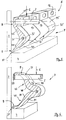
- a bed is shown, the cross slats 2 forming a slatted base 1 each end on a support bar 4 connected to the side wall 3 of a frame.
- the crossbars 2 are each resiliently mounted at the ends via a support body 5 in the vertical loading direction 6.
- the support body 5 comprises, as is clear from the enlarged sectional view according to FIG. 2, a one-piece elastic molded part 7 made of elastomeric material, which directly receives the crossbars 2 in the upper region 8 and rests on the support strip 4 with a lower support end 9.
- the molded part 7 has a bending profile which is inclined with respect to the main load direction 6 and which, in cross section, has different regions Wall thickness 10.11 offers.
- the molded part 7 can be divided into individual segments 13 by separating slots 12 from a profile strip. Instead, separate molded parts 7 can also be provided corresponding to the segments 13, which can be formed by separating them from a profiled strip.
- the segments 13 enable independent spring movements on different bending paths.
- the molded parts 7 are combined in the area of the support end 9 by means of a one-piece connecting part 14, which is supported in a sliding manner on the support bar 4 and, in an expedient embodiment, rests on a wear-reducing sliding plate 15.
- the crossbar 2 is received in a shaped engagement 16 designed as a through opening 17, which enables the crossbar 2 to be pushed in until it abuts the side wall 3.
- a further expedient plug connection between the molded parts 7 and crossbars 2 can be achieved.
- the through opening 17 or the bag opening 17 ' can also be formed on the crossbar 2, so that the plug connection can be reached with an insertion pin (not shown) formed on the upper region 8 of the molded part 7.
- the embodiment of the molded part 7 illustrated in FIG. 3 is designed with an enlarged lower support end 9, which is supported in a stable position in the operating position with conforming contact surfaces 18 on the support bar 4.
- the connection of the individual segments 13 in the longitudinal direction and thus parallel to the support bar 4 is achieved in that a formally adapted connecting part 21 is provided in a molding channel 19 in the region of the support ends 9.
- Another molding channel 20 can, at least in some segments 13, accommodate an insert 22 with play, which the Spring characteristics changed.
- a vertical support of the support end 9 is provided by a shape attachment 23 which can be placed in a stable position on the support strip 4.
- the crossbar 2 is supported in the through opening 17 by a lining 24 and extends close to the side wall 3.
- the crossbar 2 can be supported on the side wall 3 with an elastic end part 25, which can fulfill a sliding and damping function. This also applies to the embodiment according to FIGS. 2 and 6.
- the bending profile of the molded part 7 has, in the illustration according to FIG. 2, a wall thickness which increases uniformly towards the upper end 8, the profile being formed by two radii 26, 27 curved convexly to the side wall 3. With these variably designed shape radii 26, 27, the main part 28 of the molded part 7 can be adapted to different loads in spring hardness with different arch shapes between the upper end 8 and the support end 9.
- the bending profile is formed with a wall thickness 29, 30 which decreases uniformly towards the upper end 8, the form radii 31, 32 converging towards one another and entering the form recesses 16. They have an approximately horizontal course at their ends.
- the molded part 7 is formed with a bending profile directed concavely towards the side wall 3, the wall thicknesses 33, 34 decreasing towards the upper end 8 and towards the lower support end 9 starting from the reinforced main part 28.
- the molded body 7 has a molded channel 35 into which a conformal connecting part 36 is inserted, which thus stabilizes the support end 9 in the corner region 37 between the side wall 3 and the support strip 4 and adjacent molded parts 7 to form a structural unit summarizes.
- the main part 28 of the molded part 7 according to FIG. 4 shows a further possibility of varying the spring characteristic through longitudinally continuous cavities 38, 39 which, with their different shapes and their position relative to one another, have a different influence on the spring hardness in different deformation states of the support body.
- the intermediate webs 40, 41, 42 can cause a progressive, degressive, linear or even changing increase in spring hardness.
- their position in different deformation states and thus the area moment of inertia of the total cross section determining the spring hardness can be controlled in different deformation states.
- the molded part 7 is divided by the separating slots 12 into individual segments 13, which leave a connecting web 45 in the region of the support end 9, so that a common support of the segments 13 in the corner region 37 is achieved.
- One or more segments 13 '(FIG. 5) can be provided with a separating surface 32' by a cut in the area of the mold radius 32, so that a variation of the spring characteristic on any segments 13 can be achieved with little effort and different loads can be absorbed.
- FIG. 6 shows an embodiment of the molded part 7 with a bending profile which has two essentially symmetrical wave profile legs 46, 47.
- the lower wave profile leg 47 extends into the area of the support end 9 and lies directly in the corner area 37 of the frame.
- the upper corrugated profile leg 46 extends from the main part 28 in a wave shape into the upper end 8 of the molded part 7 with a through opening 17 in which a crossbar 2 is received.
- the wavy profile legs 46, 47 formed by wavy shape radii 48, 49, 50, 51 give the molded part 7 a bent profile with particularly high elasticity and progressive characteristic.
- the molded parts 7 can be provided with molded, releasable connecting members 52, 53, as shown in FIGS. 7 and 8.
- correspondingly interlocking latching hooks 54 and abutments 55 are formed in the area of the support end 9.
- FIG. 9 a side view of the support body 5 according to FIG. 5 is illustrated by its segments 13 formed by uniform separating slots 12, which accordingly enable uniform suspension in the direction of loading 6.
- a change in the width of the separating slots 12 forms a further possibility for changing the spring characteristic of segments 13.
- Independent molded parts 7 can be changed quickly and easily to change the spring characteristics, so that molded bodies 7 of different spring hardness can be strung together in any combination and provide an individual spring base for the crossbars 2 of a slatted frame 1.
Landscapes
- Springs (AREA)
- Seats For Vehicles (AREA)
- Specific Sealing Or Ventilating Devices For Doors And Windows (AREA)
Applications Claiming Priority (2)
| Application Number | Priority Date | Filing Date | Title |
|---|---|---|---|
| DE9107474U | 1991-06-17 | ||
| DE9107474U DE9107474U1 (fr) | 1991-06-17 | 1991-06-17 |
Publications (2)
| Publication Number | Publication Date |
|---|---|
| EP0519323A1 true EP0519323A1 (fr) | 1992-12-23 |
| EP0519323B1 EP0519323B1 (fr) | 1995-10-18 |
Family
ID=6868410
Family Applications (1)
| Application Number | Title | Priority Date | Filing Date |
|---|---|---|---|
| EP92109818A Expired - Lifetime EP0519323B1 (fr) | 1991-06-17 | 1992-06-11 | Support pour les lattes d'un sommier à lattes |
Country Status (3)
| Country | Link |
|---|---|
| EP (1) | EP0519323B1 (fr) |
| AT (1) | ATE129131T1 (fr) |
| DE (2) | DE9107474U1 (fr) |
Citations (2)
| Publication number | Priority date | Publication date | Assignee | Title |
|---|---|---|---|---|
| CH519319A (de) * | 1971-03-08 | 1972-02-29 | Leuzinger Rene | Liegemöbel-Gestell |
| EP0150873A2 (fr) * | 1984-01-17 | 1985-08-07 | Industrie En Handelmij Riviera B.V. | Sommier |
-
1991
- 1991-06-17 DE DE9107474U patent/DE9107474U1/de not_active Expired - Lifetime
-
1992
- 1992-06-11 DE DE59204038T patent/DE59204038D1/de not_active Expired - Fee Related
- 1992-06-11 EP EP92109818A patent/EP0519323B1/fr not_active Expired - Lifetime
- 1992-06-11 AT AT92109818T patent/ATE129131T1/de not_active IP Right Cessation
Patent Citations (2)
| Publication number | Priority date | Publication date | Assignee | Title |
|---|---|---|---|---|
| CH519319A (de) * | 1971-03-08 | 1972-02-29 | Leuzinger Rene | Liegemöbel-Gestell |
| EP0150873A2 (fr) * | 1984-01-17 | 1985-08-07 | Industrie En Handelmij Riviera B.V. | Sommier |
Also Published As
| Publication number | Publication date |
|---|---|
| DE59204038D1 (de) | 1995-11-23 |
| DE9107474U1 (fr) | 1992-10-15 |
| ATE129131T1 (de) | 1995-11-15 |
| EP0519323B1 (fr) | 1995-10-18 |
Similar Documents
| Publication | Publication Date | Title |
|---|---|---|
| EP1959797B1 (fr) | Matelas | |
| DE29914501U1 (de) | Innenrückblickspiegel für Fahrzeuge | |
| DE2905138C2 (fr) | ||
| DE2945174C2 (de) | Umlenkbeschlag für den Sicherheitsgurt eines Rückhaltesystems | |
| EP1086637B1 (fr) | Sous-matelas ou analogue, ainsi que ses applications | |
| AT393210B (de) | Einlage fuer ein bett in form eines lattenrostes | |
| DD297497A5 (de) | Energiefuehrungskette | |
| DE3048793C2 (de) | Tragkörper für Radführungsglieder von Kraftfahrzeugrädern, insbesondere Hinterrädern | |
| CH668513A5 (de) | Zusammenbaubares gehaeuse, verwendung als spleissgehaeuse fuer kabel. | |
| EP2266823B1 (fr) | Dispositif de chauffage électrique | |
| CH678375A5 (fr) | ||
| EP0599051B1 (fr) | Elément de support pour vitres de fenêtres, portes et similaires | |
| EP0519323B1 (fr) | Support pour les lattes d'un sommier à lattes | |
| DE2061723C3 (de) | Schiebewiderstand | |
| DE2344770A1 (de) | Rahmen fuer liegemoebel | |
| EP0020943A1 (fr) | Pinces de suspension pour conducteurs et faisceaux de conducteurs isolés | |
| DE3101215A1 (de) | "vorrichtung zur lagerung und aufnahme von jeweils wenigstens zwei federleisten an den seitenteilen eines bettrahmens" | |
| DE20116382U1 (de) | Transportband | |
| WO2007121957A1 (fr) | Chaîne transporteuse | |
| DE2749248C2 (de) | Energieführungskette | |
| DE10112597B4 (de) | Rohrkettenförderer für Transport oder Dosieren von insbesondere Schüttgut | |
| DE7143368U (de) | Endlosbandförderer | |
| DE10349146B4 (de) | Federelement für ein Unterbett | |
| EP0754816B1 (fr) | Grille à barreaux | |
| DE19945735A1 (de) | Federungselement für ein Lattenrost |
Legal Events
| Date | Code | Title | Description |
|---|---|---|---|
| PUAI | Public reference made under article 153(3) epc to a published international application that has entered the european phase |
Free format text: ORIGINAL CODE: 0009012 |
|
| AK | Designated contracting states |
Kind code of ref document: A1 Designated state(s): AT BE CH DE DK ES FR GB IT LI LU NL SE |
|
| 17P | Request for examination filed |
Effective date: 19930618 |
|
| 17Q | First examination report despatched |
Effective date: 19941223 |
|
| GRAA | (expected) grant |
Free format text: ORIGINAL CODE: 0009210 |
|
| AK | Designated contracting states |
Kind code of ref document: B1 Designated state(s): AT BE CH DE DK ES FR GB IT LI LU NL SE |
|
| PG25 | Lapsed in a contracting state [announced via postgrant information from national office to epo] |
Ref country code: ES Free format text: THE PATENT HAS BEEN ANNULLED BY A DECISION OF A NATIONAL AUTHORITY Effective date: 19951018 Ref country code: DK Effective date: 19951018 Ref country code: GB Effective date: 19951018 Ref country code: IT Free format text: LAPSE BECAUSE OF FAILURE TO SUBMIT A TRANSLATION OF THE DESCRIPTION OR TO PAY THE FEE WITHIN THE PRE;WARNING: LAPSES OF ITALIAN PATENTS WITH EFFECTIVE DATE BEFORE 2007 MAY HAVE OCCURRED AT ANY TIME BEFORE 2007. THE CORRECT EFFECTIVE DATE MAY BE DIFFERENT FROM THE ONE RECORDED.SCRIBED TIME-LIMIT Effective date: 19951018 |
|
| REF | Corresponds to: |
Ref document number: 129131 Country of ref document: AT Date of ref document: 19951115 Kind code of ref document: T |
|
| REF | Corresponds to: |
Ref document number: 59204038 Country of ref document: DE Date of ref document: 19951123 |
|
| PG25 | Lapsed in a contracting state [announced via postgrant information from national office to epo] |
Ref country code: SE Effective date: 19960118 |
|
| ET | Fr: translation filed | ||
| GBV | Gb: ep patent (uk) treated as always having been void in accordance with gb section 77(7)/1977 [no translation filed] |
Effective date: 19951018 |
|
| PG25 | Lapsed in a contracting state [announced via postgrant information from national office to epo] |
Ref country code: LU Free format text: LAPSE BECAUSE OF NON-PAYMENT OF DUE FEES Effective date: 19960630 |
|
| PGFP | Annual fee paid to national office [announced via postgrant information from national office to epo] |
Ref country code: FR Payment date: 19960709 Year of fee payment: 5 |
|
| PLBE | No opposition filed within time limit |
Free format text: ORIGINAL CODE: 0009261 |
|
| STAA | Information on the status of an ep patent application or granted ep patent |
Free format text: STATUS: NO OPPOSITION FILED WITHIN TIME LIMIT |
|
| 26N | No opposition filed | ||
| PGFP | Annual fee paid to national office [announced via postgrant information from national office to epo] |
Ref country code: AT Payment date: 19970606 Year of fee payment: 6 |
|
| PGFP | Annual fee paid to national office [announced via postgrant information from national office to epo] |
Ref country code: BE Payment date: 19970731 Year of fee payment: 6 |
|
| PGFP | Annual fee paid to national office [announced via postgrant information from national office to epo] |
Ref country code: DE Payment date: 19970825 Year of fee payment: 6 |
|
| PG25 | Lapsed in a contracting state [announced via postgrant information from national office to epo] |
Ref country code: FR Free format text: LAPSE BECAUSE OF NON-PAYMENT OF DUE FEES Effective date: 19980227 |
|
| REG | Reference to a national code |
Ref country code: FR Ref legal event code: ST |
|
| REG | Reference to a national code |
Ref country code: FR Ref legal event code: ST |
|
| PG25 | Lapsed in a contracting state [announced via postgrant information from national office to epo] |
Ref country code: AT Free format text: LAPSE BECAUSE OF NON-PAYMENT OF DUE FEES Effective date: 19980611 |
|
| PG25 | Lapsed in a contracting state [announced via postgrant information from national office to epo] |
Ref country code: BE Free format text: LAPSE BECAUSE OF NON-PAYMENT OF DUE FEES Effective date: 19980630 |
|
| PGFP | Annual fee paid to national office [announced via postgrant information from national office to epo] |
Ref country code: NL Payment date: 19980630 Year of fee payment: 7 |
|
| PGFP | Annual fee paid to national office [announced via postgrant information from national office to epo] |
Ref country code: CH Payment date: 19981007 Year of fee payment: 7 |
|
| BERE | Be: lapsed |
Owner name: HEERKLOTZ SIEGFRIED Effective date: 19980630 |
|
| PG25 | Lapsed in a contracting state [announced via postgrant information from national office to epo] |
Ref country code: DE Free format text: LAPSE BECAUSE OF NON-PAYMENT OF DUE FEES Effective date: 19990401 |
|
| PG25 | Lapsed in a contracting state [announced via postgrant information from national office to epo] |
Ref country code: LI Free format text: LAPSE BECAUSE OF NON-PAYMENT OF DUE FEES Effective date: 19990630 Ref country code: CH Free format text: LAPSE BECAUSE OF NON-PAYMENT OF DUE FEES Effective date: 19990630 |
|
| PG25 | Lapsed in a contracting state [announced via postgrant information from national office to epo] |
Ref country code: NL Free format text: LAPSE BECAUSE OF NON-PAYMENT OF DUE FEES Effective date: 20000101 |
|
| REG | Reference to a national code |
Ref country code: CH Ref legal event code: PL |
|
| NLV4 | Nl: lapsed or anulled due to non-payment of the annual fee |
Effective date: 20000101 |