EP0519192B1 - Flüssigkeitsringpumpe - Google Patents
Flüssigkeitsringpumpe Download PDFInfo
- Publication number
- EP0519192B1 EP0519192B1 EP92107460A EP92107460A EP0519192B1 EP 0519192 B1 EP0519192 B1 EP 0519192B1 EP 92107460 A EP92107460 A EP 92107460A EP 92107460 A EP92107460 A EP 92107460A EP 0519192 B1 EP0519192 B1 EP 0519192B1
- Authority
- EP
- European Patent Office
- Prior art keywords
- plate
- pump
- catch
- liquid ring
- ring pump
- Prior art date
- Legal status (The legal status is an assumption and is not a legal conclusion. Google has not performed a legal analysis and makes no representation as to the accuracy of the status listed.)
- Expired - Lifetime
Links
- 239000007788 liquid Substances 0.000 title claims description 13
- 238000007689 inspection Methods 0.000 claims description 3
- 238000006073 displacement reaction Methods 0.000 description 3
- 230000002950 deficient Effects 0.000 description 1
Images
Classifications
-
- F—MECHANICAL ENGINEERING; LIGHTING; HEATING; WEAPONS; BLASTING
- F04—POSITIVE - DISPLACEMENT MACHINES FOR LIQUIDS; PUMPS FOR LIQUIDS OR ELASTIC FLUIDS
- F04C—ROTARY-PISTON, OR OSCILLATING-PISTON, POSITIVE-DISPLACEMENT MACHINES FOR LIQUIDS; ROTARY-PISTON, OR OSCILLATING-PISTON, POSITIVE-DISPLACEMENT PUMPS
- F04C29/00—Component parts, details or accessories of pumps or pumping installations, not provided for in groups F04C18/00 - F04C28/00
- F04C29/12—Arrangements for admission or discharge of the working fluid, e.g. constructional features of the inlet or outlet
- F04C29/124—Arrangements for admission or discharge of the working fluid, e.g. constructional features of the inlet or outlet with inlet and outlet valves specially adapted for rotary or oscillating piston pumps
- F04C29/126—Arrangements for admission or discharge of the working fluid, e.g. constructional features of the inlet or outlet with inlet and outlet valves specially adapted for rotary or oscillating piston pumps of the non-return type
- F04C29/128—Arrangements for admission or discharge of the working fluid, e.g. constructional features of the inlet or outlet with inlet and outlet valves specially adapted for rotary or oscillating piston pumps of the non-return type of the elastic type, e.g. reed valves
-
- F—MECHANICAL ENGINEERING; LIGHTING; HEATING; WEAPONS; BLASTING
- F04—POSITIVE - DISPLACEMENT MACHINES FOR LIQUIDS; PUMPS FOR LIQUIDS OR ELASTIC FLUIDS
- F04C—ROTARY-PISTON, OR OSCILLATING-PISTON, POSITIVE-DISPLACEMENT MACHINES FOR LIQUIDS; ROTARY-PISTON, OR OSCILLATING-PISTON, POSITIVE-DISPLACEMENT PUMPS
- F04C19/00—Rotary-piston pumps with fluid ring or the like, specially adapted for elastic fluids
- F04C19/005—Details concerning the admission or discharge
- F04C19/007—Port members in the form of side plates
Definitions
- the invention relates to a liquid ring pump according to the preamble of claim 1.
- Such a liquid ring pump is known from DE-A-27 04 863.
- the valve plates are arranged and fastened together with the catch plates on the control disk. This means increased assembly effort.
- the side plate must be removed in order to be able to replace the valve plate.
- the invention has for its object to design a liquid ring pump of the generic type so that the valve plate is much easier to attach in front of the pressure openings.
- the problem is solved by the features specified in the characterizing part of claim 1. Because the catch plate is connected to the side plate, there is no need for separate mounting on the control disk. The valve plate only needs to be plugged onto the guide elements. Since the valve plate is no longer clamped on one side, it can stand out equally from all pressure openings, so that the outflow of the gas from the pressure openings is not impeded.
- a further relief when assembling the pump is when the catch plate is integrally formed on the side plate.
- the replacement of a defective valve plate or the control of its functionality is possible without dismantling larger parts of the pump in that the catch plate is arranged on a closure plate, through which an inspection opening provided in the side plate is covered.
- valve plate can be plugged onto the guide elements before the side plate or the closure plate is assembled.
- a further easing of assembly is when the pins or sleeves are fastened in the receiving bores of the catch plate or the control disk.
- control disk 6 which closes off the end of the pump chamber.
- This control disk 6 has at least one in connection with the suction chamber 7 of the side plate 1 standing inlet slot 8 and several in the pressure chamber 9 of the side plate 1 opening pressure openings 10, of which only one is shown in the drawing. The area of the control disk 6 provided with the pressure openings 10 is shown rotated into the plane of the drawing.
- a valve plate 11 is assigned to the pressure openings 10, which opens or covers the pressure openings 10 in accordance with the prevailing operating conditions.
- a catch plate 12 molded onto the side plate 1 is assigned to the valve plate 11.
- Pins or sleeves 14 are inserted with their ends into receiving bores 13 provided on the catch plate 12 and the control disk 6 opposite one another. The pins or sleeves 14 pass through guide openings 15 provided on the valve plate 11.
- An axial displacement of the valve plate 11 is possible on the pins or sleeves 14 in the area between the control disk 6 and the catch plate 12.
- the pressure openings 10 are opened or closed by the axial displacement of the valve plate 11. Individual or all pressure openings 10 are closed or opened in accordance with the prevailing pressure conditions.
- the catch plate 12 is provided on a closure plate 16, which serves to close an inspection opening 17 of the side plate 1. After removing this closure plate 16, the valve plate 11 can be checked or, in the event of damage, also replaced.
- a plurality of receiving bores 13 spaced apart from one another are provided on the catch plate 12 and thus also on the control disk 6.
- good guidance of the valve plate 11 is achieved by means of the pins or sleeves 14 inserted into these receiving bores.
- the pins or sleeves 14 can either be fastened in the receiving bores 13 of the control disk 6 or in the receiving bores 13 of the catch plate 12.
- the valve plate 11 with its guide openings 15 is pushed onto these attached pins or sleeves 14.
- the pins or sleeves 14 engage in the opposite receiving bores 13 of the catch plate 12 or the control disk 6, so that the valve plate 11 is completely secured.
Landscapes
- Engineering & Computer Science (AREA)
- Mechanical Engineering (AREA)
- General Engineering & Computer Science (AREA)
- Structures Of Non-Positive Displacement Pumps (AREA)
Description
- Die Erfindung bezieht sich auf eine Flüssigkeitsringpumpe gemäß dem Oberbegriff des Anspruchs 1.
- Eine solche Flüssigkeitsringpumpe ist durch die DE-A-27 04 863 bekannt. Bei dieser Pumpe sind die Ventilplatten zusammen mit den Fangplatten an der Steuerscheibe angeordnet und befestigt. Dies bedeutet einen erhöhten Montageaufwand. Ferner muß bei einer Zerstörung oder Abnutzung der Ventilplatte während des späteren Betriebes der Pumpe das Seitenschild demontiert werden, um die Ventilplatte austauschen zu können.
- Der Erfindung liegt die Aufgabe zugrunde, eine Flüssigkeitsringpumpe der gattungsgemäßen Art so auszugestalten, daß die Ventilplatte wesentlich einfacher vor den Drucköffnungen anzubringen ist.
- Die Lösung der gestellten Aufgabe gelingt durch die im Kennzeichen des Anspruchs 1 angegebenen Merkmale. Dadurch, daß die Fangplatte mit dem Seitenschild verbunden ist, entfällt deren gesonderte Montage an der Steuerscheibe. Die Ventilplatte braucht lediglich auf die Führungselemente aufgesteckt zu werden. Da die Ventilplatte nicht mehr einseitig festgeklemmt ist, kann sie sich von allen Drucköffnungen gleichweit abheben, so daß das Ausströmen des Gases aus den Drucköffnungen nicht behindert wird.
- Eine weitere Erleichterung bei der Montage der Pumpe ist es, wenn die Fangplatte einteilig am Seitenschild angeformt ist.
- Der Austausch einer defekten Ventilplatte bzw. die Kontrolle derer Funktionsfähigkeit ist ohne Demontage größerer Teile der Pumpe dadurch möglich, daß die Fangplatte an einer Verschlußplatte angeordnet ist, durch die eine im Seitenschild vorgesehene Inspektionsöffnung abgedeckt ist.
- Dadurch, daß als Führungselemente Stifte oder Hülsen vorgesehen sind, die in entsprechende Aufnahmebohrungen an der Fangplatte und/oder der Steuerscheibe eingreifen, kann die Ventilplatte vor der Montage des Seitenschildes bzw. der Verschlußplatte auf die Führungselemente aufgesteckt werden. Eine weitere Montageerleichterung ist es, wenn die Stifte oder Hülsen in den Aufnahmebohrungen der Fangplatte oder der Steuerscheibe befestigt sind.
- Anhand eines in der Zeichnung dargestellten Ausführungsbeispieles wird der Anmeldungsgegenstand nachfolgend näher beschrieben. Es zeigt:
- FIG 1
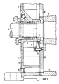
- eine Flüssigkeitsringpumpe im Teilschnitt, bei der am Seitenschild eine Fangplatte angeformt ist,
- FIG 2
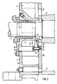
- eine Flüssigkeitsringpumpe im Teilschnitt, bei der die Fangplatte an einer am Seitenschild befestigbaren Verschlußplatte angeordnet ist und
- FIG 3
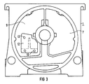
- eine Draufsicht eines Seitenschildes mit angeformter Fangplatte.
- Mit 1 ist ein am Pumpengehäuse 2 einer Flüssigkeitsringpumpe montiertes Seitenschild bezeichnet. Dieses Seitenschild 1 weist eine Wellenbohrung 3 auf, durch die die Welle 4 des Laufrades 5 der Pumpe abgedichtet hindurchgeführt ist. Zwischen dem Seitenschild 1 und dem Pumpengehäuse 2 ist eine den Pumpenraum stirnseitig abschließende Steuerscheibe 6 angeordnet. Diese Steuerscheibe 6 weist mindestens einen mit der Ansaugkammer 7 des Seitenschildes 1 in Verbindung stehenden Einlaßschlitz 8 und mehere in die Druckkammer 9 des Seitenschildes 1 mündende Drucköffnungen 10 auf, von denen in der Zeichnung nur eine dargestellt ist. Der mit den Drucköffnungen 10 versehene Bereich der Steuerscheibe 6 ist in die Zeichnungsebene gedreht dargestellt.
- Den Drucköffnungen 10 ist eine Ventilplatte 11 zugeordnet, welche die Drucköffnungen 10 entsprechend der jeweils vorliegenden Betriebsverhältnisse freigibt oder abdeckt. Der Ventilplatte 11 ist eine am Seitenschild 1 angeformte Fangplatte 12 zugeordnet. In an der Fangplatte 12 und der Steuerscheibe 6 einander gegenüberliegend vorgesehene Aufnahmebohrungen 13 sind Stifte oder Hülsen 14 mit ihren Enden eingesteckt. Die Stifte bzw. Hülsen 14 greifen durch an der Ventilplatte 11 vorhandene Führungsöffnungen 15 hindurch. Damit ist die Ventilplatte 11 gegenüber den Drucköffnungen 10 lagemäßig gesichert. Eine axiale Verschiebung der Ventilplatte 11 ist auf den Stiften bzw. Hülsen 14 in dem Bereich zwischen der Steuerscheibe 6 und der Fangplatte 12 möglich. Durch die axiale Verschiebung der Ventilplatte 11 erfolgt je nach Verschieberichtung ein Öffnen oder Verschließen der Drucköffnungen 10. Dabei werden entsprechend der herrschenden Druckverhältnisse einzelne oder alle Drucköffnungen 10 verschlossen oder geöffnet.
- Bei der in FIG 2 dargestellten Ausführungsvarianten einer Flüssigkeitsringpumpe ist die Fangplatte 12 an einer Verschlußplatte 16 vorgesehen, die zum Verschließen einer Inspektionsöffnung 17 des Seitenschildes 1 dient. Nach Abnehmen dieser Verschlußplatte 16 kann die Ventilplatte 11 kontrolliert oder im Schadensfalle auch ausgetauscht werden.
- Wie aus der FIG 3 deutlich wird, sind an der Fangplatte 12 und damit auch an der Steuerscheibe 6 mehrere voneinander beabstandete Aufnahmebohrungen 13 vorgesehen. Durch diese verteilte Anordnung der Aufnahmebohrungen 13 wird eine gute Führung der Ventilplatte 11 mittels der in diese Aufnahmebohrungen eingesetzten Stifte bzw. Hülsen 14 erreicht.
- Die Stifte bzw. Hülsen 14 können entweder in den Aufnahmebohrungen 13 der Steuerscheibe 6 oder in den Aufnahmebohrungen 13 der Fangplatte 12 befestigt werden. Auf diese befestigten Stifte bzw. Hülsen 14 wird die Ventilplatte 11 mit ihren Führungsöffnungen 15 aufgesteckt. Beim Anbringen des Seitenschildes 1 oder der Verschlußplatte 16 greifen die Stifte bzw. Hülsen 14 dann in die gegenüberliegenden Aufnahmebohrungen 13 der Fangplatte 12 bzw. der Steuerscheibe 6 ein, damit ist die Ventilplatte 11 vollständig gesichert.
Claims (5)
- Flüssigkeitsringpumpe, bei der in dem vom Pumpengehäuse (2) gebildeten Pumpenraum das Laufrad (5) der Pumpe drehbar angeordnet ist, welcher Pumpenraum mindestens auf einer Stirnseite mittels einer mindestens einen Einlaßschlitz (8) und mehrere Drucköffnungen (10) aufweisenden Steuerscheibe (6) abgeschlossen ist, die von einem am Pumpengehäuse (2) angeordneten Seitenschild (1) überdeckt ist, zwischen dem und der Steuerscheibe (6) eine mit dem Einlaßschlitz (8) in Verbindung stehende Ansaugkammer (7) und eine mit den Drucköffnungen (10) in Verbindung stehende Druckkammer (9) besteht, bei welcher Pumpe ferner zumindest ein Teil der Drucköffnungen (10) durch mindestens eine von diesen abhebbare und an einer gehäusefesten Fangplatte (12) abstützbare Ventilplatte (11) überdeckt ist, dadurch gekennzeichnet, daß die Fangplatte (12) mit dem Seitenschild (1) verbunden und die Ventilplatte (11) durch zwischen der Fangplatte (12) und der Steuerscheibe (6) angeordnete durch entsprechende Öffnungen (15) der Ventilplatte (11) durchgreifende Führungselemente (14) geführt ist.
- Flüssigkeitsringpumpe nach Anspruch 1,
dadurch gekennzeichnet, daß die Fangplatte (12) einteilig an dem Seitenschild (1) angeformt ist. - Flüssigkeitsringpumpe nach Anspruch 1,
dadurch gekennzeichnet, daß die Fangplatte (12) an einer Verschlußplatte (16) angeordnet ist, durch die eine im Seitenschild (1) vorgesehene Inspektionsöffnung (17) abgedeckt ist. - Flüssigkeitsringpumpe nach Anspruch 1,2 oder 3,
dadurch gekennzeichnet, daß als Führungselemente Stifte oder Hülsen (14) vorgesehen sind, die in entsprechende, an der Fangplatte (12) und/oder der Steuerscheibe (6) vorgesehene Aufnahmebohrungen (13) eingreifen. - Flüssigkeitsringpumpe nach Anspruch 4,
dadurch gekennzeichnet, daß die Stifte bzw. Hülsen (14) in den Aufnahmebohrungen (13) der Fangplatte (12) oder den Aufnahmebohrungen (13) der Steuerscheibe (6) befestigt sind.
Applications Claiming Priority (2)
| Application Number | Priority Date | Filing Date | Title |
|---|---|---|---|
| DE9106151U DE9106151U1 (de) | 1991-05-17 | 1991-05-17 | Flüssigkeitsringpumpe |
| DE9106151U | 1991-05-17 |
Publications (2)
| Publication Number | Publication Date |
|---|---|
| EP0519192A1 EP0519192A1 (de) | 1992-12-23 |
| EP0519192B1 true EP0519192B1 (de) | 1995-02-15 |
Family
ID=6867444
Family Applications (1)
| Application Number | Title | Priority Date | Filing Date |
|---|---|---|---|
| EP92107460A Expired - Lifetime EP0519192B1 (de) | 1991-05-17 | 1992-04-30 | Flüssigkeitsringpumpe |
Country Status (6)
| Country | Link |
|---|---|
| US (1) | US5211543A (de) |
| EP (1) | EP0519192B1 (de) |
| JP (1) | JPH05157075A (de) |
| AU (1) | AU646562B2 (de) |
| CA (1) | CA2068812A1 (de) |
| DE (2) | DE9106151U1 (de) |
Cited By (1)
| Publication number | Priority date | Publication date | Assignee | Title |
|---|---|---|---|---|
| CN104114869A (zh) * | 2011-11-24 | 2014-10-22 | 斯特林工业咨询有限公司 | 液环真空泵 |
Families Citing this family (2)
| Publication number | Priority date | Publication date | Assignee | Title |
|---|---|---|---|---|
| DE19727719C1 (de) * | 1997-06-30 | 1998-06-25 | Siemens Ag | Flüssigkeitsringpumpe |
| DE29805345U1 (de) | 1998-03-24 | 1998-08-06 | Siemens AG, 80333 München | Flüssigkeitsringpumpe |
Family Cites Families (5)
| Publication number | Priority date | Publication date | Assignee | Title |
|---|---|---|---|---|
| US1931198A (en) * | 1930-11-26 | 1933-10-17 | Norge Corp | Compressor discharge valve |
| DE1503605B2 (de) * | 1965-04-28 | 1971-05-27 | Siemens AG, 1000 Berlin u 8000 München | Rueckschlagventil fuer eine fluessigkeitsringgaspumpe |
| GB2064002A (en) * | 1979-11-22 | 1981-06-10 | Graham Precision Pumps Ltd | Liquid Ring Vacuum Pumps |
| DE3337837A1 (de) * | 1983-10-18 | 1985-04-25 | Siemens AG, 1000 Berlin und 8000 München | Fluessigkeitsringpumpe |
| GB2217814B (en) * | 1988-04-27 | 1992-10-14 | American Standard Inc | Rotary compressors having backflow preventing valves |
-
1991
- 1991-05-17 DE DE9106151U patent/DE9106151U1/de not_active Expired - Lifetime
-
1992
- 1992-04-09 US US07/865,997 patent/US5211543A/en not_active Expired - Lifetime
- 1992-04-30 DE DE59201384T patent/DE59201384D1/de not_active Expired - Fee Related
- 1992-04-30 EP EP92107460A patent/EP0519192B1/de not_active Expired - Lifetime
- 1992-05-13 JP JP4146948A patent/JPH05157075A/ja not_active Withdrawn
- 1992-05-15 CA CA002068812A patent/CA2068812A1/en not_active Abandoned
- 1992-05-15 AU AU16339/92A patent/AU646562B2/en not_active Ceased
Cited By (3)
| Publication number | Priority date | Publication date | Assignee | Title |
|---|---|---|---|---|
| CN104114869A (zh) * | 2011-11-24 | 2014-10-22 | 斯特林工业咨询有限公司 | 液环真空泵 |
| CN104114869B (zh) * | 2011-11-24 | 2017-08-11 | 斯特林工业咨询有限公司 | 液环真空泵 |
| US9964110B2 (en) | 2011-11-24 | 2018-05-08 | Sterling Industry Consult Gmbh | Bearing arrangement and wear indicator for a liquid ring vacuum pump |
Also Published As
| Publication number | Publication date |
|---|---|
| AU646562B2 (en) | 1994-02-24 |
| DE59201384D1 (de) | 1995-03-23 |
| US5211543A (en) | 1993-05-18 |
| EP0519192A1 (de) | 1992-12-23 |
| CA2068812A1 (en) | 1992-11-18 |
| AU1633992A (en) | 1992-11-19 |
| DE9106151U1 (de) | 1992-09-17 |
| JPH05157075A (ja) | 1993-06-22 |
Similar Documents
| Publication | Publication Date | Title |
|---|---|---|
| DE68911842T2 (de) | Filtersystem. | |
| EP0308618A2 (de) | Rückschlagventil, insbesondere für Druckluft | |
| DE68903322T2 (de) | Doppeloelfilter fuer oel fuer verbrennungsmotoren von motorfahrzeugen. | |
| EP0519192B1 (de) | Flüssigkeitsringpumpe | |
| DE2337465C2 (de) | Flüssigkeitszähler | |
| EP1159998B1 (de) | Flüssigkeitsfilter | |
| DE4425344C2 (de) | Drehschieber mit mindestens einem Axialnadeldrehkranz als drehbewegliches Lagerelement | |
| DE2744917A1 (de) | Sitzventil mit geradem durchgang | |
| EP2178615B1 (de) | Filterplatte | |
| EP1611339B1 (de) | Kraftstofffilter für ein kraftfahrzeug | |
| EP0742371B1 (de) | Flüssigkeitsringmaschine | |
| EP1020647B1 (de) | Plattenventil | |
| EP0339104A1 (de) | Armatur | |
| DE2630875A1 (de) | Luftfilter fuer brennkraftmaschinen, kompressoren und sonstige luftansaugende maschinen | |
| EP0174492B1 (de) | Stromregelventil | |
| DE102023113316A1 (de) | Einfach zu montierende Standpumpe | |
| DE69816204T2 (de) | Vorrichtung zur Unterstützung der Motoreinheit eines Ventilators | |
| DE2443175C3 (de) | Vorrichtung in Schreibmaschinen zum schwenkbaren Lagern der oberen Gehäuseabdeckung | |
| DE3112403C2 (de) | ||
| DD281219A5 (de) | Anschlusskopplung fuer oelfilter an kraft- oder arbeitsmaschinen | |
| DE3625808A1 (de) | Koksofentuer | |
| DE2730222C3 (de) | Geradstromventil | |
| DE1137228B (de) | Scharnier zur aufklappbaren Anordnung von Gehaeusedeckeln an Messgeraeten | |
| DE3016003A1 (de) | Ringfoermiges plattenventil | |
| DE3831859A1 (de) | Luftfeder mit einer vorrichtung zur leitungsverbindung |
Legal Events
| Date | Code | Title | Description |
|---|---|---|---|
| PUAI | Public reference made under article 153(3) epc to a published international application that has entered the european phase |
Free format text: ORIGINAL CODE: 0009012 |
|
| AK | Designated contracting states |
Kind code of ref document: A1 Designated state(s): BE DE FR GB IT SE |
|
| 17P | Request for examination filed |
Effective date: 19930122 |
|
| 17Q | First examination report despatched |
Effective date: 19940726 |
|
| GRAA | (expected) grant |
Free format text: ORIGINAL CODE: 0009210 |
|
| AK | Designated contracting states |
Kind code of ref document: B1 Designated state(s): BE DE FR GB IT SE |
|
| REF | Corresponds to: |
Ref document number: 59201384 Country of ref document: DE Date of ref document: 19950323 |
|
| GBT | Gb: translation of ep patent filed (gb section 77(6)(a)/1977) |
Effective date: 19950322 |
|
| ITF | It: translation for a ep patent filed | ||
| ET | Fr: translation filed | ||
| PLBE | No opposition filed within time limit |
Free format text: ORIGINAL CODE: 0009261 |
|
| STAA | Information on the status of an ep patent application or granted ep patent |
Free format text: STATUS: NO OPPOSITION FILED WITHIN TIME LIMIT |
|
| 26N | No opposition filed | ||
| PGFP | Annual fee paid to national office [announced via postgrant information from national office to epo] |
Ref country code: BE Payment date: 19990419 Year of fee payment: 8 |
|
| PGFP | Annual fee paid to national office [announced via postgrant information from national office to epo] |
Ref country code: SE Payment date: 20000418 Year of fee payment: 9 |
|
| PG25 | Lapsed in a contracting state [announced via postgrant information from national office to epo] |
Ref country code: BE Free format text: LAPSE BECAUSE OF NON-PAYMENT OF DUE FEES Effective date: 20000430 |
|
| BERE | Be: lapsed |
Owner name: SIEMENS A.G. Effective date: 20000430 |
|
| PG25 | Lapsed in a contracting state [announced via postgrant information from national office to epo] |
Ref country code: SE Free format text: LAPSE BECAUSE OF NON-PAYMENT OF DUE FEES Effective date: 20010501 |
|
| REG | Reference to a national code |
Ref country code: GB Ref legal event code: IF02 |
|
| REG | Reference to a national code |
Ref country code: GB Ref legal event code: 732E |
|
| PGFP | Annual fee paid to national office [announced via postgrant information from national office to epo] |
Ref country code: GB Payment date: 20040416 Year of fee payment: 13 |
|
| PGFP | Annual fee paid to national office [announced via postgrant information from national office to epo] |
Ref country code: FR Payment date: 20040421 Year of fee payment: 13 |
|
| REG | Reference to a national code |
Ref country code: FR Ref legal event code: TP |
|
| PGFP | Annual fee paid to national office [announced via postgrant information from national office to epo] |
Ref country code: DE Payment date: 20040630 Year of fee payment: 13 |
|
| PG25 | Lapsed in a contracting state [announced via postgrant information from national office to epo] |
Ref country code: IT Free format text: LAPSE BECAUSE OF NON-PAYMENT OF DUE FEES;WARNING: LAPSES OF ITALIAN PATENTS WITH EFFECTIVE DATE BEFORE 2007 MAY HAVE OCCURRED AT ANY TIME BEFORE 2007. THE CORRECT EFFECTIVE DATE MAY BE DIFFERENT FROM THE ONE RECORDED. Effective date: 20050430 Ref country code: GB Free format text: LAPSE BECAUSE OF NON-PAYMENT OF DUE FEES Effective date: 20050430 |
|
| PG25 | Lapsed in a contracting state [announced via postgrant information from national office to epo] |
Ref country code: DE Free format text: LAPSE BECAUSE OF NON-PAYMENT OF DUE FEES Effective date: 20051101 |
|
| GBPC | Gb: european patent ceased through non-payment of renewal fee |
Effective date: 20050430 |
|
| PG25 | Lapsed in a contracting state [announced via postgrant information from national office to epo] |
Ref country code: FR Free format text: LAPSE BECAUSE OF NON-PAYMENT OF DUE FEES Effective date: 20051230 |
|
| REG | Reference to a national code |
Ref country code: FR Ref legal event code: ST Effective date: 20051230 |