EP0519121A2 - Planetenschaltgetriebe mit einer Freilaufkupplung - Google Patents
Planetenschaltgetriebe mit einer Freilaufkupplung Download PDFInfo
- Publication number
- EP0519121A2 EP0519121A2 EP91122129A EP91122129A EP0519121A2 EP 0519121 A2 EP0519121 A2 EP 0519121A2 EP 91122129 A EP91122129 A EP 91122129A EP 91122129 A EP91122129 A EP 91122129A EP 0519121 A2 EP0519121 A2 EP 0519121A2
- Authority
- EP
- European Patent Office
- Prior art keywords
- gear
- speed changing
- changing mechanism
- planet
- internal gear
- Prior art date
- Legal status (The legal status is an assumption and is not a legal conclusion. Google has not performed a legal analysis and makes no representation as to the accuracy of the status listed.)
- Granted
Links
Images

Classifications
-
- F—MECHANICAL ENGINEERING; LIGHTING; HEATING; WEAPONS; BLASTING
- F16—ENGINEERING ELEMENTS AND UNITS; GENERAL MEASURES FOR PRODUCING AND MAINTAINING EFFECTIVE FUNCTIONING OF MACHINES OR INSTALLATIONS; THERMAL INSULATION IN GENERAL
- F16H—GEARING
- F16H3/00—Toothed gearings for conveying rotary motion with variable gear ratio or for reversing rotary motion
- F16H3/44—Toothed gearings for conveying rotary motion with variable gear ratio or for reversing rotary motion using gears having orbital motion
- F16H3/62—Gearings having three or more central gears
- F16H3/64—Gearings having three or more central gears composed of a number of gear trains, the drive always passing through all the trains, each train having not more than one connection for driving another train
-
- B—PERFORMING OPERATIONS; TRANSPORTING
- B25—HAND TOOLS; PORTABLE POWER-DRIVEN TOOLS; MANIPULATORS
- B25B—TOOLS OR BENCH DEVICES NOT OTHERWISE PROVIDED FOR, FOR FASTENING, CONNECTING, DISENGAGING OR HOLDING
- B25B21/00—Portable power-driven screw or nut setting or loosening tools; Attachments for drilling apparatus serving the same purpose
- B25B21/008—Portable power-driven screw or nut setting or loosening tools; Attachments for drilling apparatus serving the same purpose with automatic change-over from high speed-low torque mode to low speed-high torque mode
Definitions
- the present invention relates to a speed changing mechanism which includes planet gears and is used with an electric rotary tool, an electric press-attaching tool, an automatic screw tightening tool or the like. More particularly, the invention relates to a speed changing mechanism which includes planet gears and a one-way clutch and is used with the above-mentioned tools.
- a speed changing mechanism which includes planet gears has a simple construction and the input and output shafts of the mechanism can be disposed coaxially, the mechanism has been widely used as a speed reducer for an electric rotary tool such as an electric screwdriver, an electric screw tightener or a vibratory drill.
- Such speed changing mechanisms are disclosed in Japanese Patent Unexamined Publication Nos. Sho. 62-173180 and 62-297006. Due to the gear combination of each of these conventional speed changers, the ratio of the rapid rotation speed of the mechanism to the slow rotation speed thereof is 2.5 or greater, and cannot be set to a value as small as 1.5.
- an electric press-attaching tool including an automatic speed changing mechanism, which is powered by a battery, and a hydraulic pump, which is driven by the mechanism.
- the tool need not have a separately disposed pump, a separately laid pressure-proof hose or a manipulation lever for increasing the working oil pressure.
- the tool's operation is unrestricted by the movement of the user thereof, and is easily handled.
- a force for pressing and deforming a press-attachable terminal or sleeve or the like by the tool is to be weak, such as when connecting thin electric wires or a small number thereof together by the terminal or sleeve or the like, the tool's rotational frequency is increased, thereby decreasing the output torque thereof and shortening the tool's working time.
- a strong force is required such as when connecting thick electric wires or a large number of electric wires together by the terminal or sleeve or the like, the tool's rotational frequency is automatically decreased, thereby increasing the output torque thereof.
- the force magnitude can be adjusted appropriately for the work to be performed by the tool.
- a ratio of the mechanism's rapid rotation speed to the slow rotation speed thereof must be set to approximately 1.5.
- the conventional speed changing mechanisms do not meet this requirement, and thus a problem arises in that an appropriate working force is not applied to a workpiece.
- the present invention was designed to solve the above-mentioned problem. Accordingly, it is an object of the invention to provide a speed changing mechanism which can be set to have a ratio of its rapid rotation speed to its slow rotation speed to 2.5 or less, thereby allowing the speed changing mechanism to be used as a drive system for a machine, such as an electric press-attaching tool, having little difference between its rapid rotation speed and its slow rotation speed.
- the inventive speed changing mechanism includes: planet gears; a first planet gear support plate integrally formed with an internal gear and provided with a first fitting mechanism, such as an external gear, formed outwardly of the internal gear; a second planet gear support plate which is mounted on a driven shaft and integrally formed with a second fitting mechanism, such as an external gear, which has an equivalent structure to that of the first fitting mechanism and by which the planet gears engaged with the internal gear are rotatably supported; a cylindrical member including a mechanism such as an internal gear, which is slidably fitted with at least one of the two fitting mechanisms formed on the two planet gear support plates; and a one-way clutch which is mounted with a sun gear engaged with the planet gears and which is rotatable in exclusively one direction.
- a speed changing mechanism comprising: a rotatable member having an internal gear; a planet gear carrier coaxially provided with the rotatable member and securely fixed to an output shaft; planet gears rotatably supported on the planet gear carrier and meshed with the internal gear; a sun gear coaxially provided with the rotatable member and meshed with the planet gears; a one-way clutch for enabling the sun gear to be rotated in exclusively one direction; and a coupling mechanism for operatively, selectively coupling the rotatable member to the planet gear carrier to rotate the rotatable member and the planet gear carrier together.
- a rotational torque transmitted to the rotatable member is directly transmitted from the rotatable member to the planet gear carrier when the rotatable member is coupled to the planet gear carrier by the coupling mechanism.
- a rotational torque transmitted to the rotatable member is increased and transmitted from the rotatable member to the planet gear carrier through the planet gears meshed with the sun gear which is prevented by the one-way clutch from being rotated when the rotatable member is not coupled to the planet gear carrier by the coupling mechanism.
- the coupling mechanism preferably includes a first external gear formed on the rotatable member outwardly of the internal gear, a second external gear formed on a peripheral portion of the planet gear carrier, and a cylindrical member fitted around the rotatable member and the planet carrier and slidable thereon so that the first external gear selectively engages and disengages the second external gear by the cylindrical member.
- the cylindrical member preferably includes an internal gear engageable with the first and second external gears.
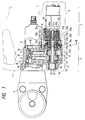
- FIG. 1 is a partial and axial sectional side view of an electric press-attaching tool having an automatic speed changing mechanism which is an embodiment of the present invention and which includes planet gears and a one-way clutch.
- the tool includes a cover 1, an automatic speed changing mechanism unit 2, a hydraulic pump 3, a head 4, and a gear case 10.
- the automatic speed changing mechanism unit 2 includes an electric motor 20, and the automatic speed changing mechanism.
- the automatic speed changing mechanism includes a first-stage sun gear 21a, first-stage planet gears 21b, a first-stage internal gear 21c, a first-stage planet gear support plate 21d, a second-stage sun gear 22a, second-stage planet gears 22b, a second-stage internal gear 22c, a second-stage planet gear support plate 22d, a third-stage sun gear 23a, third-stage planet gears 23b, a third-stage internal gear 23c, a third-stage planet gear support plate 23d, an external gear 23e, a fourth-stage sun gear 24a, fourth-stage planet gears 24b, a fourth-stage internal gear 24c, a fourth-stage planet gear support plate 24d, an external gear 24e, a one-way clutch shaft 25, and an internal gear 26.
- the sun gears, the planet gears and the internal gear are rotated by the electric motor 20 when the motor is driven by a portable battery (not shown in the drawings).
- the first-stage sun gear 21a is mounted on the rotary shaft 20a of the motor 20 and is securely fixed thereto.
- the first-stage planet gears 21b are engaged with the first-stage sun gear 21a and the first-stage internal gear 21c secured to the gear case 10 which is a cylindrical member.
- the first-stage planet gears 21b are rotatably supported by the first-stage planet gear support plate 21d integrally formed with the second-stage sun gear 22a on the central portion of the plate opposite the planet gears.
- the second-stage planet gears 22b are engaged with the second-stage sun gear 22a and the second-stage internal gear 22c secured to the gear case 10, and are rotatably supported by the second-stage planet gear support plate 22d integrally formed with the third-stage sun gear 23a on the central portion of the plate opposite the planet gears.
- the third-stage planet gears 23b are engaged with the third-stage sun gear 23a and the third-stage internal gears 23c secured to the gear case 10, and are rotatably supported by the third-stage planet gear support plate 23d integrally formed with the fourth-stage internal gear 24c and the external gear 23e.
- the fourth-stage planet gears 24b are engaged with the fourth-stage internal gear 24c, and are rotatably supported by the fourth-stage planet gear support plate 24d integrally formed with the external gear 24e and spline-coupled to an eccentric shaft 5.
- the fourth-stage sun gear 24a is mounted on the one-way clutch shaft 25 at one end thereof and securely fixed thereto.
- the internal gear 26 is engaged with either both the external gears 23e and 24e or with only the external gear 24e, by a sliding mechanism described hereinafter.
- the one-way clutch shaft 25 is coupled at the other end thereof with a one-way clutch 37 in the gear case 10 so that the shaft can be rotated in only one direction.
- the hydraulic pump 3 includes the eccentric shaft 5, and a hydraulic circuit between an oil tank 6 and the head 4 of the tool, and pump 3 applies high pressure to the head.
- the eccentric shaft 5, which is spline-coupled to the fourth-stage planet gear support plate 24d of the automatic speed changing mechanism, includes a central portion 5a, and two eccentric portions 5b having different angular positions.
- the shaft 5 is rotatably supported at one end thereof with a roller bearing in an outer ring 27 fitted in the gear case 10, and is rotatably supported at another end thereof with a roller bearing in the gear case.
- the hydraulic pump 3 also includes cam plungers 51, 52 mounted at first ends thereof on needle bearings on the eccentric portions 5b of the shaft 5, and fitted at the second ends thereof in first and second cylindrical chambers 31, 32 so that the plungers are reciprocated therein as the shaft is rotated.
- working oil is sent from the oil tank 6 to the first cylindrical chamber 31 through a check valve 8 and a first feed passage 33, or to the second cylindrical chamber 32 through another check valve 8 and a second oil feed passage 34, so that the oil pressure is increased.
- the pressurized oil is conveyed to a cylindrical chamber 35 through a check valve 9 so that a piston 36 fitted in the chamber formed in the front portion of the hydraulic pump 3 is pushed to press and deform a press-attachable terminal (or the like) on the tool head 4 to connect electric wires or the like together by the terminal.
- Figure 2 is a sectional view of the mechanism along lines II-II of Figure 1, but with certain components not shown (e.g., the planet gears, etc.).
- the magnitude of the torque transmitted from the mechanism to the eccentric shaft 5 of the hydraulic pump 3 as the shaft 5 is rotated with the fourth-stage planet gear support plate 24d can be adjusted by sliding the internal gear 26 in first or second directions (i.e., in the directions of arrows B or C shown in Figure 1).
- a shift lever 11 is disposed outside the gear case 10 and is coupled at both its ends to pins 12 fitted in a groove 26a provided in the peripheral surface of the internal gear 26 and extending in the circumferential direction thereof, as shown in FIG. 2.
- the shift lever 11 is pivoted about screw pins 13 engaged in the tapped holes of the gear case.
- the pivoting operation is performed by a solenoid actuator 63, having a pin 64 coupled at an end thereof to a link 15 coupled to the central portion of the shift lever 11, which is driven by a prescribed electrical current.
- Juts e.g., a projecting member
- the internal gear 26 When the internal gear 26 is in the position C shown in FIG. 1 and the motor 20 is driven, the internal gear 26 is engaged with the external gear 23e on the third-stage planet gear support plate 23d and the external gear 24e on the fourth-stage planet gear support plate 24d and rotates both the support plates together.
- the fourth-stage planet gears 24b rotatably supported by the fourth-stage planet gear support plate 24d and engaged with the fourth-stage sun gear 24a, are revolved together with the sun gear around the axis thereof but not rotated around the axes of the planet gears. Consequently, the speed changing mechanism does not perform a speed reducing action.
- the sun gear 24a is rotated in such a direction to allow the one-way clutch 37 to rotate, and the fourth-stage planet gear support plate 24d is rapidly rotated.
- the torque transmitted from the mechanism to the eccentric shaft 5 has a low magnitude, and the working oil pressure generated in the hydraulic circuit of the pump 3 is low.
- a weak press-attaching force is applied to the tool head 4, and the piston 36 is rapidly moved, thereby making the time required for the press-attaching operation of the terminal or the like relatively short.
- the internal gear 26 When the internal gear 26 is in position B shown in FIG. 1 and the motor 20 is driven, the internal gear 26 engages the external gear 23e on the third-stage planet gear support plate 23d, but does not engage the external gear 24e on the fourth-stage planet gear support plate 24d, and the fourth-stage sun gear 24a receives torque in such a direction that the one-way clutch 37 does not rotate. Thus, the rotation of the fourth-stage sun gear 24a is hindered by the clutch.
- the fourth-stage sun gear 24a, the fourth-stage internal gear 24c integrally formed on the third-stage planet gear support plate 23d, and the fourth-stage planet gears 24b form a speed reducer which receives input torque at the internal gear and sends out output torque at the planet gears, and the fourth-stage planet gear support plate 24d is slowly rotated.
- i0 denotes the ratio of the number of teeth of the fourth-stage internal gear 24c to that of the teeth of the fourth-stage sun gear 24a. If the ratio i0 is 2, the speed reduction ratio I is 1/1.5. Thus the ratio of the above-mentioned rapid rotation speed to the above-mentioned slow rotation speed can be set at 1.5/1.
- a speed changing mechanism provided according to the present invention and including a one-way clutch and planet gears has a simple and compact construction. Additionally, the mechanism's input shaft and output shaft can be disposed coaxially.
- the conventional speed changing mechanism which includes planet gears and is provided in an electric rotary tool or the like has a ratio of the mechanism's rapid rotation speed to its slow rotation speed which cannot be set below 2.5. Thus, even assuming work can be efficiently performed by the rapid rotation, work cannot be performed efficiently by the slow rotation.
- the conventional mechanism's output torque is high enough at its slow rotation speed, but not at its rapid rotation speed.
- the conventional mechanism cannot be used to drive an electric press-attaching tool or the like, which must be set to have a small ratio of its rapid rotation speed to its slow rotation speed.
- the inventive speed changing mechanism being applied to the electric press-attaching tool or the like.
- the inventive speed changing mechanism can be operated optimally depending on the load on such a tool, and hence the inventive speed changing mechanism can drive various machines in which input and output shafts thereof need to be disposed coaxially and the ratio of the machine's rapid rotation speed to its slow rotation speed must be set at no more than 2.5.
Landscapes
- Engineering & Computer Science (AREA)
- Mechanical Engineering (AREA)
- General Engineering & Computer Science (AREA)
- Structure Of Transmissions (AREA)
- Drilling And Boring (AREA)
- Percussive Tools And Related Accessories (AREA)
Applications Claiming Priority (2)
| Application Number | Priority Date | Filing Date | Title |
|---|---|---|---|
| JP414653/90 | 1990-12-26 | ||
| JP2414653A JPH0810019B2 (ja) | 1990-12-26 | 1990-12-26 | ワンウェイクラッチを組込んだ遊星歯車変速機構 |
Publications (3)
| Publication Number | Publication Date |
|---|---|
| EP0519121A2 true EP0519121A2 (de) | 1992-12-23 |
| EP0519121A3 EP0519121A3 (en) | 1993-12-08 |
| EP0519121B1 EP0519121B1 (de) | 1997-04-16 |
Family
ID=18523104
Family Applications (1)
| Application Number | Title | Priority Date | Filing Date |
|---|---|---|---|
| EP91122129A Expired - Lifetime EP0519121B1 (de) | 1990-12-26 | 1991-12-23 | Planetenschaltgetriebe mit einer Freilaufkupplung |
Country Status (4)
| Country | Link |
|---|---|
| US (1) | US5176593A (de) |
| EP (1) | EP0519121B1 (de) |
| JP (1) | JPH0810019B2 (de) |
| DE (1) | DE69125709T2 (de) |
Cited By (5)
| Publication number | Priority date | Publication date | Assignee | Title |
|---|---|---|---|---|
| CN1065158C (zh) * | 1998-06-22 | 2001-05-02 | 福光企业股份有限公司 | 锻造部品成型机专用的齿轮变速机构 |
| US6984188B2 (en) | 2001-01-23 | 2006-01-10 | Black & Decker Inc. | Multispeed power tool transmission |
| US7101300B2 (en) | 2001-01-23 | 2006-09-05 | Black & Decker Inc. | Multispeed power tool transmission |
| WO2011123959A1 (de) * | 2010-04-09 | 2011-10-13 | Bruderer Ag | Getriebeeinheit und anordnung für eine stanzpresse |
| US8205685B2 (en) | 2006-02-03 | 2012-06-26 | Black & Decker Inc. | Housing and gearbox for drill or driver |
Families Citing this family (6)
| Publication number | Priority date | Publication date | Assignee | Title |
|---|---|---|---|---|
| US6796921B1 (en) | 2003-05-30 | 2004-09-28 | One World Technologies Limited | Three speed rotary power tool |
| US7367358B2 (en) * | 2005-02-02 | 2008-05-06 | Universal Infusion Technology, Llc | Medical fluid delivery system and method relating to the same |
| JP4527468B2 (ja) * | 2004-08-17 | 2010-08-18 | 株式会社マキタ | 電動工具 |
| JP2007226175A (ja) * | 2006-01-26 | 2007-09-06 | Epson Imaging Devices Corp | 液晶装置及び電子機器 |
| US8251158B2 (en) | 2008-11-08 | 2012-08-28 | Black & Decker Inc. | Multi-speed power tool transmission with alternative ring gear configuration |
| JP2012016775A (ja) * | 2010-07-07 | 2012-01-26 | Makita Corp | オイルパルス回転工具 |
Family Cites Families (18)
| Publication number | Priority date | Publication date | Assignee | Title |
|---|---|---|---|---|
| US832442A (en) * | 1904-07-15 | 1906-10-02 | James Archer | Variable-speed gear. |
| US2380390A (en) * | 1941-06-14 | 1945-07-31 | New Prod Corp | Change-speed gearing for aircraft propellers |
| US2787173A (en) * | 1952-04-30 | 1957-04-02 | Karl J Kollmann | Change-speed gearing, particularly for bicycles or the like |
| US3018673A (en) * | 1958-01-13 | 1962-01-30 | Aro Equipment Corp | Transmission |
| US3430521A (en) * | 1967-06-19 | 1969-03-04 | Ingersoll Rand Co | Power-operated tool having two-speed rotary output |
| US3477314A (en) * | 1967-11-28 | 1969-11-11 | Massey Ferguson Inc | Change speed planetary transmission |
| GB1404063A (en) * | 1972-05-24 | 1975-08-28 | Desoutter Brothers Ltd | Power driven rotary tool |
| JPS5439197Y2 (de) * | 1975-05-29 | 1979-11-20 | ||
| DE2533308A1 (de) * | 1975-07-25 | 1977-02-17 | Fichtel & Sachs Ag | Mehrgangnabe fuer fahrraeder o.dgl. |
| JPS53115455A (en) * | 1977-03-17 | 1978-10-07 | Nippon Denso Co Ltd | Two-stage change-over system transmission mechanism |
| DE3329295C2 (de) * | 1983-08-12 | 1987-01-29 | Alfing Montagetechnik GmbH, 7080 Aalen | Motorisch angetriebenes Schraubwerkzeug |
| DE3525208A1 (de) * | 1984-07-16 | 1986-01-23 | Japan Strage Battery Co. Ltd., Kyoto | Untersetzungsgetriebe |
| JPS62173180A (ja) * | 1986-01-27 | 1987-07-30 | 松下電工株式会社 | 振動ドリル |
| JPS62297006A (ja) * | 1986-06-14 | 1987-12-24 | Matsushita Electric Works Ltd | 振動ドリル |
| JPS63101546A (ja) * | 1986-10-15 | 1988-05-06 | Matsushita Electric Works Ltd | 遊星変速装置の切換機構 |
| US4869139A (en) * | 1987-06-19 | 1989-09-26 | Alexander S. Gotman | Rotating driver with automatic speed and torque switching |
| DE3934283A1 (de) * | 1988-10-14 | 1990-05-03 | Hitachi Koki Kk | Schaltgetriebe fuer eine elektrisch angetriebene werkzeugmaschine |
| US4938738A (en) * | 1989-05-22 | 1990-07-03 | General Motors Corporation | Two-speed drive arrangement |
-
1990
- 1990-12-26 JP JP2414653A patent/JPH0810019B2/ja not_active Expired - Fee Related
-
1991
- 1991-12-23 DE DE69125709T patent/DE69125709T2/de not_active Expired - Fee Related
- 1991-12-23 EP EP91122129A patent/EP0519121B1/de not_active Expired - Lifetime
- 1991-12-24 US US07/812,940 patent/US5176593A/en not_active Expired - Lifetime
Cited By (13)
| Publication number | Priority date | Publication date | Assignee | Title |
|---|---|---|---|---|
| CN1065158C (zh) * | 1998-06-22 | 2001-05-02 | 福光企业股份有限公司 | 锻造部品成型机专用的齿轮变速机构 |
| US6984188B2 (en) | 2001-01-23 | 2006-01-10 | Black & Decker Inc. | Multispeed power tool transmission |
| US7101300B2 (en) | 2001-01-23 | 2006-09-05 | Black & Decker Inc. | Multispeed power tool transmission |
| US7220211B2 (en) | 2001-01-23 | 2007-05-22 | Black & Decker Inc. | Multispeed power tool transmission |
| US7223195B2 (en) | 2001-01-23 | 2007-05-29 | Black & Decker Inc. | Multispeed power tool transmission |
| US7410441B2 (en) | 2001-01-23 | 2008-08-12 | Black & Decker Inc. | Multispeed power tool transmission |
| US9579785B2 (en) | 2006-02-03 | 2017-02-28 | Black & Decker Inc. | Power tool with transmission cassette received in clam shell housing |
| US8205685B2 (en) | 2006-02-03 | 2012-06-26 | Black & Decker Inc. | Housing and gearbox for drill or driver |
| US10987793B2 (en) | 2006-02-03 | 2021-04-27 | Black & Decker Inc. | Power tool with tool housing and output spindle housing |
| WO2011123959A1 (de) * | 2010-04-09 | 2011-10-13 | Bruderer Ag | Getriebeeinheit und anordnung für eine stanzpresse |
| CN102834647B (zh) * | 2010-04-09 | 2016-05-11 | 布吕德雷股份公司 | 用于冲压压力机的传动单元和装置 |
| US8727931B2 (en) | 2010-04-09 | 2014-05-20 | Bruderer Ag | Gear train unit and arrangement for a stamping press |
| CN102834647A (zh) * | 2010-04-09 | 2012-12-19 | 布吕德雷股份公司 | 用于冲压压力机的传动单元和装置 |
Also Published As
| Publication number | Publication date |
|---|---|
| EP0519121A3 (en) | 1993-12-08 |
| JPH0810019B2 (ja) | 1996-01-31 |
| JPH04224343A (ja) | 1992-08-13 |
| DE69125709T2 (de) | 1997-07-24 |
| DE69125709D1 (de) | 1997-05-22 |
| EP0519121B1 (de) | 1997-04-16 |
| US5176593A (en) | 1993-01-05 |
Similar Documents
| Publication | Publication Date | Title |
|---|---|---|
| EP0519121B1 (de) | Planetenschaltgetriebe mit einer Freilaufkupplung | |
| US4791833A (en) | Reduction gear mechanism for motor-driven drill incorporating speed changing mechanism | |
| EP1050381B1 (de) | Drehschlagwerkzeug | |
| EP0349482B1 (de) | Motorisch betriebenes Handwerkzeug | |
| US5019023A (en) | Speed changer mechanism for electrically powered tool | |
| US12479073B2 (en) | Eccentric transmission for a power tool | |
| US5513546A (en) | Device for fastening and loosening threaded members | |
| US12343855B2 (en) | Spring element and coupling device | |
| US10751869B2 (en) | Speed-changing tool | |
| US20230415313A1 (en) | Coupling mechanism | |
| JPH01140918A (ja) | 二段変速トランスミッション装置を含む動力駆動ねじ切り盤 | |
| EP0564604A1 (de) | Lineareinheit mit zwei geschwindigkeiten angetrieben von zwei motoren. | |
| EP0470741A1 (de) | Schraubgerät | |
| US11054002B2 (en) | Planetary geared reducer with dual reduction ratio | |
| EP1878945B1 (de) | Getriebe mit schrittweiser Änderung der Getriebeübersetzung | |
| US4643037A (en) | Gear change mechanism | |
| US5573357A (en) | Portable, handheld, power tool | |
| EP0336239A1 (de) | Kupplungsmechanismus in einem Zahnradgetriebe | |
| JP2617031B2 (ja) | 変速機構付電動圧着工具 | |
| EP0791434A1 (de) | Klemmvorrichtung mit Reduktionsgetriebe | |
| JPH04262151A (ja) | 一定電流時によるソレノイド作動を利用した自動変速機構 | |
| US4680894A (en) | Fixture for honing thin wall gear parts | |
| US4914871A (en) | Method for honing thin wall gear parts | |
| KR100415482B1 (ko) | 기계프레스의슬라이드구동장치 | |
| JPH05164209A (ja) | 回転運動を直進運動に変換する動力伝達方法及び装置 |
Legal Events
| Date | Code | Title | Description |
|---|---|---|---|
| PUAI | Public reference made under article 153(3) epc to a published international application that has entered the european phase |
Free format text: ORIGINAL CODE: 0009012 |
|
| AK | Designated contracting states |
Kind code of ref document: A2 Designated state(s): CH DE FR GB IT LI NL |
|
| PUAL | Search report despatched |
Free format text: ORIGINAL CODE: 0009013 |
|
| AK | Designated contracting states |
Kind code of ref document: A3 Designated state(s): CH DE FR GB IT LI NL |
|
| 17P | Request for examination filed |
Effective date: 19940211 |
|
| 17Q | First examination report despatched |
Effective date: 19950426 |
|
| GRAG | Despatch of communication of intention to grant |
Free format text: ORIGINAL CODE: EPIDOS AGRA |
|
| GRAH | Despatch of communication of intention to grant a patent |
Free format text: ORIGINAL CODE: EPIDOS IGRA |
|
| GRAH | Despatch of communication of intention to grant a patent |
Free format text: ORIGINAL CODE: EPIDOS IGRA |
|
| GRAA | (expected) grant |
Free format text: ORIGINAL CODE: 0009210 |
|
| AK | Designated contracting states |
Kind code of ref document: B1 Designated state(s): CH DE FR GB IT LI NL |
|
| REG | Reference to a national code |
Ref country code: CH Ref legal event code: NV Representative=s name: MICHELI & CIE INGENIEURS-CONSEILS Ref country code: CH Ref legal event code: EP |
|
| REF | Corresponds to: |
Ref document number: 69125709 Country of ref document: DE Date of ref document: 19970522 |
|
| ET | Fr: translation filed | ||
| PLBE | No opposition filed within time limit |
Free format text: ORIGINAL CODE: 0009261 |
|
| STAA | Information on the status of an ep patent application or granted ep patent |
Free format text: STATUS: NO OPPOSITION FILED WITHIN TIME LIMIT |
|
| 26N | No opposition filed | ||
| REG | Reference to a national code |
Ref country code: GB Ref legal event code: IF02 |
|
| PGFP | Annual fee paid to national office [announced via postgrant information from national office to epo] |
Ref country code: CH Payment date: 20020115 Year of fee payment: 11 |
|
| PGFP | Annual fee paid to national office [announced via postgrant information from national office to epo] |
Ref country code: NL Payment date: 20021227 Year of fee payment: 12 |
|
| PG25 | Lapsed in a contracting state [announced via postgrant information from national office to epo] |
Ref country code: LI Free format text: LAPSE BECAUSE OF NON-PAYMENT OF DUE FEES Effective date: 20021231 Ref country code: CH Free format text: LAPSE BECAUSE OF NON-PAYMENT OF DUE FEES Effective date: 20021231 |
|
| REG | Reference to a national code |
Ref country code: CH Ref legal event code: PL |
|
| PG25 | Lapsed in a contracting state [announced via postgrant information from national office to epo] |
Ref country code: NL Free format text: LAPSE BECAUSE OF NON-PAYMENT OF DUE FEES Effective date: 20040701 |
|
| NLV4 | Nl: lapsed or anulled due to non-payment of the annual fee |
Effective date: 20040701 |
|
| PGFP | Annual fee paid to national office [announced via postgrant information from national office to epo] |
Ref country code: GB Payment date: 20041222 Year of fee payment: 14 |
|
| PGFP | Annual fee paid to national office [announced via postgrant information from national office to epo] |
Ref country code: FR Payment date: 20051208 Year of fee payment: 15 |
|
| PGFP | Annual fee paid to national office [announced via postgrant information from national office to epo] |
Ref country code: DE Payment date: 20051215 Year of fee payment: 15 |
|
| PG25 | Lapsed in a contracting state [announced via postgrant information from national office to epo] |
Ref country code: IT Free format text: LAPSE BECAUSE OF NON-PAYMENT OF DUE FEES;WARNING: LAPSES OF ITALIAN PATENTS WITH EFFECTIVE DATE BEFORE 2007 MAY HAVE OCCURRED AT ANY TIME BEFORE 2007. THE CORRECT EFFECTIVE DATE MAY BE DIFFERENT FROM THE ONE RECORDED. Effective date: 20051223 Ref country code: GB Free format text: LAPSE BECAUSE OF NON-PAYMENT OF DUE FEES Effective date: 20051223 |
|
| REG | Reference to a national code |
Ref country code: FR Ref legal event code: TP |
|
| GBPC | Gb: european patent ceased through non-payment of renewal fee |
Effective date: 20051223 |
|
| PG25 | Lapsed in a contracting state [announced via postgrant information from national office to epo] |
Ref country code: DE Free format text: LAPSE BECAUSE OF NON-PAYMENT OF DUE FEES Effective date: 20070703 |
|
| REG | Reference to a national code |
Ref country code: FR Ref legal event code: ST Effective date: 20070831 |
|
| PG25 | Lapsed in a contracting state [announced via postgrant information from national office to epo] |
Ref country code: FR Free format text: LAPSE BECAUSE OF NON-PAYMENT OF DUE FEES Effective date: 20070102 |