EP0516580A1 - Dispositif de ravitaillement d'un réservoir à combustible gazeux - Google Patents
Dispositif de ravitaillement d'un réservoir à combustible gazeux Download PDFInfo
- Publication number
- EP0516580A1 EP0516580A1 EP92810282A EP92810282A EP0516580A1 EP 0516580 A1 EP0516580 A1 EP 0516580A1 EP 92810282 A EP92810282 A EP 92810282A EP 92810282 A EP92810282 A EP 92810282A EP 0516580 A1 EP0516580 A1 EP 0516580A1
- Authority
- EP
- European Patent Office
- Prior art keywords
- pressure
- compressor
- pressure vessel
- line
- housing
- Prior art date
- Legal status (The legal status is an assumption and is not a legal conclusion. Google has not performed a legal analysis and makes no representation as to the accuracy of the status listed.)
- Granted
Links
- 239000002828 fuel tank Substances 0.000 title claims description 3
- 239000007789 gas Substances 0.000 claims abstract description 25
- 239000000446 fuel Substances 0.000 claims abstract description 22
- VNWKTOKETHGBQD-UHFFFAOYSA-N methane Chemical compound C VNWKTOKETHGBQD-UHFFFAOYSA-N 0.000 claims abstract description 16
- 239000003345 natural gas Substances 0.000 claims abstract description 8
- 238000001816 cooling Methods 0.000 claims description 26
- 238000012544 monitoring process Methods 0.000 claims description 8
- 238000009434 installation Methods 0.000 claims description 6
- 238000005192 partition Methods 0.000 claims description 2
- 230000000149 penetrating effect Effects 0.000 claims 1
- 238000007789 sealing Methods 0.000 description 5
- 230000006835 compression Effects 0.000 description 2
- 238000007906 compression Methods 0.000 description 2
- 238000010276 construction Methods 0.000 description 2
- 230000008878 coupling Effects 0.000 description 2
- 238000010168 coupling process Methods 0.000 description 2
- 238000005859 coupling reaction Methods 0.000 description 2
- 238000007689 inspection Methods 0.000 description 2
- 238000012423 maintenance Methods 0.000 description 2
- 230000003111 delayed effect Effects 0.000 description 1
- 230000001419 dependent effect Effects 0.000 description 1
- 238000010586 diagram Methods 0.000 description 1
- 230000000694 effects Effects 0.000 description 1
- 230000002349 favourable effect Effects 0.000 description 1
- 239000012535 impurity Substances 0.000 description 1
- 230000000717 retained effect Effects 0.000 description 1
- 238000011144 upstream manufacturing Methods 0.000 description 1
Images

Classifications
-
- F—MECHANICAL ENGINEERING; LIGHTING; HEATING; WEAPONS; BLASTING
- F17—STORING OR DISTRIBUTING GASES OR LIQUIDS
- F17C—VESSELS FOR CONTAINING OR STORING COMPRESSED, LIQUEFIED OR SOLIDIFIED GASES; FIXED-CAPACITY GAS-HOLDERS; FILLING VESSELS WITH, OR DISCHARGING FROM VESSELS, COMPRESSED, LIQUEFIED, OR SOLIDIFIED GASES
- F17C5/00—Methods or apparatus for filling containers with liquefied, solidified, or compressed gases under pressures
- F17C5/002—Automated filling apparatus
- F17C5/007—Automated filling apparatus for individual gas tanks or containers, e.g. in vehicles
-
- B—PERFORMING OPERATIONS; TRANSPORTING
- B60—VEHICLES IN GENERAL
- B60S—SERVICING, CLEANING, REPAIRING, SUPPORTING, LIFTING, OR MANOEUVRING OF VEHICLES, NOT OTHERWISE PROVIDED FOR
- B60S5/00—Servicing, maintaining, repairing, or refitting of vehicles
- B60S5/02—Supplying fuel to vehicles; General disposition of plant in filling stations
-
- F—MECHANICAL ENGINEERING; LIGHTING; HEATING; WEAPONS; BLASTING
- F02—COMBUSTION ENGINES; HOT-GAS OR COMBUSTION-PRODUCT ENGINE PLANTS
- F02B—INTERNAL-COMBUSTION PISTON ENGINES; COMBUSTION ENGINES IN GENERAL
- F02B43/00—Engines characterised by operating on gaseous fuels; Plants including such engines
-
- F—MECHANICAL ENGINEERING; LIGHTING; HEATING; WEAPONS; BLASTING
- F17—STORING OR DISTRIBUTING GASES OR LIQUIDS
- F17C—VESSELS FOR CONTAINING OR STORING COMPRESSED, LIQUEFIED OR SOLIDIFIED GASES; FIXED-CAPACITY GAS-HOLDERS; FILLING VESSELS WITH, OR DISCHARGING FROM VESSELS, COMPRESSED, LIQUEFIED, OR SOLIDIFIED GASES
- F17C2205/00—Vessel construction, in particular mounting arrangements, attachments or identifications means
- F17C2205/01—Mounting arrangements
- F17C2205/0103—Exterior arrangements
- F17C2205/0111—Boxes
-
- F—MECHANICAL ENGINEERING; LIGHTING; HEATING; WEAPONS; BLASTING
- F17—STORING OR DISTRIBUTING GASES OR LIQUIDS
- F17C—VESSELS FOR CONTAINING OR STORING COMPRESSED, LIQUEFIED OR SOLIDIFIED GASES; FIXED-CAPACITY GAS-HOLDERS; FILLING VESSELS WITH, OR DISCHARGING FROM VESSELS, COMPRESSED, LIQUEFIED, OR SOLIDIFIED GASES
- F17C2205/00—Vessel construction, in particular mounting arrangements, attachments or identifications means
- F17C2205/03—Fluid connections, filters, valves, closure means or other attachments
- F17C2205/0302—Fittings, valves, filters, or components in connection with the gas storage device
- F17C2205/0323—Valves
- F17C2205/0329—Valves manually actuated
-
- F—MECHANICAL ENGINEERING; LIGHTING; HEATING; WEAPONS; BLASTING
- F17—STORING OR DISTRIBUTING GASES OR LIQUIDS
- F17C—VESSELS FOR CONTAINING OR STORING COMPRESSED, LIQUEFIED OR SOLIDIFIED GASES; FIXED-CAPACITY GAS-HOLDERS; FILLING VESSELS WITH, OR DISCHARGING FROM VESSELS, COMPRESSED, LIQUEFIED, OR SOLIDIFIED GASES
- F17C2205/00—Vessel construction, in particular mounting arrangements, attachments or identifications means
- F17C2205/03—Fluid connections, filters, valves, closure means or other attachments
- F17C2205/0302—Fittings, valves, filters, or components in connection with the gas storage device
- F17C2205/0323—Valves
- F17C2205/0332—Safety valves or pressure relief valves
-
- F—MECHANICAL ENGINEERING; LIGHTING; HEATING; WEAPONS; BLASTING
- F17—STORING OR DISTRIBUTING GASES OR LIQUIDS
- F17C—VESSELS FOR CONTAINING OR STORING COMPRESSED, LIQUEFIED OR SOLIDIFIED GASES; FIXED-CAPACITY GAS-HOLDERS; FILLING VESSELS WITH, OR DISCHARGING FROM VESSELS, COMPRESSED, LIQUEFIED, OR SOLIDIFIED GASES
- F17C2205/00—Vessel construction, in particular mounting arrangements, attachments or identifications means
- F17C2205/03—Fluid connections, filters, valves, closure means or other attachments
- F17C2205/0302—Fittings, valves, filters, or components in connection with the gas storage device
- F17C2205/0323—Valves
- F17C2205/0335—Check-valves or non-return valves
-
- F—MECHANICAL ENGINEERING; LIGHTING; HEATING; WEAPONS; BLASTING
- F17—STORING OR DISTRIBUTING GASES OR LIQUIDS
- F17C—VESSELS FOR CONTAINING OR STORING COMPRESSED, LIQUEFIED OR SOLIDIFIED GASES; FIXED-CAPACITY GAS-HOLDERS; FILLING VESSELS WITH, OR DISCHARGING FROM VESSELS, COMPRESSED, LIQUEFIED, OR SOLIDIFIED GASES
- F17C2205/00—Vessel construction, in particular mounting arrangements, attachments or identifications means
- F17C2205/03—Fluid connections, filters, valves, closure means or other attachments
- F17C2205/0302—Fittings, valves, filters, or components in connection with the gas storage device
- F17C2205/0338—Pressure regulators
-
- F—MECHANICAL ENGINEERING; LIGHTING; HEATING; WEAPONS; BLASTING
- F17—STORING OR DISTRIBUTING GASES OR LIQUIDS
- F17C—VESSELS FOR CONTAINING OR STORING COMPRESSED, LIQUEFIED OR SOLIDIFIED GASES; FIXED-CAPACITY GAS-HOLDERS; FILLING VESSELS WITH, OR DISCHARGING FROM VESSELS, COMPRESSED, LIQUEFIED, OR SOLIDIFIED GASES
- F17C2205/00—Vessel construction, in particular mounting arrangements, attachments or identifications means
- F17C2205/03—Fluid connections, filters, valves, closure means or other attachments
- F17C2205/0302—Fittings, valves, filters, or components in connection with the gas storage device
- F17C2205/0341—Filters
-
- F—MECHANICAL ENGINEERING; LIGHTING; HEATING; WEAPONS; BLASTING
- F17—STORING OR DISTRIBUTING GASES OR LIQUIDS
- F17C—VESSELS FOR CONTAINING OR STORING COMPRESSED, LIQUEFIED OR SOLIDIFIED GASES; FIXED-CAPACITY GAS-HOLDERS; FILLING VESSELS WITH, OR DISCHARGING FROM VESSELS, COMPRESSED, LIQUEFIED, OR SOLIDIFIED GASES
- F17C2221/00—Handled fluid, in particular type of fluid
- F17C2221/03—Mixtures
- F17C2221/032—Hydrocarbons
- F17C2221/033—Methane, e.g. natural gas, CNG, LNG, GNL, GNC, PLNG
-
- F—MECHANICAL ENGINEERING; LIGHTING; HEATING; WEAPONS; BLASTING
- F17—STORING OR DISTRIBUTING GASES OR LIQUIDS
- F17C—VESSELS FOR CONTAINING OR STORING COMPRESSED, LIQUEFIED OR SOLIDIFIED GASES; FIXED-CAPACITY GAS-HOLDERS; FILLING VESSELS WITH, OR DISCHARGING FROM VESSELS, COMPRESSED, LIQUEFIED, OR SOLIDIFIED GASES
- F17C2223/00—Handled fluid before transfer, i.e. state of fluid when stored in the vessel or before transfer from the vessel
- F17C2223/01—Handled fluid before transfer, i.e. state of fluid when stored in the vessel or before transfer from the vessel characterised by the phase
- F17C2223/0107—Single phase
- F17C2223/0123—Single phase gaseous, e.g. CNG, GNC
-
- F—MECHANICAL ENGINEERING; LIGHTING; HEATING; WEAPONS; BLASTING
- F17—STORING OR DISTRIBUTING GASES OR LIQUIDS
- F17C—VESSELS FOR CONTAINING OR STORING COMPRESSED, LIQUEFIED OR SOLIDIFIED GASES; FIXED-CAPACITY GAS-HOLDERS; FILLING VESSELS WITH, OR DISCHARGING FROM VESSELS, COMPRESSED, LIQUEFIED, OR SOLIDIFIED GASES
- F17C2223/00—Handled fluid before transfer, i.e. state of fluid when stored in the vessel or before transfer from the vessel
- F17C2223/03—Handled fluid before transfer, i.e. state of fluid when stored in the vessel or before transfer from the vessel characterised by the pressure level
- F17C2223/036—Very high pressure (>80 bar)
-
- F—MECHANICAL ENGINEERING; LIGHTING; HEATING; WEAPONS; BLASTING
- F17—STORING OR DISTRIBUTING GASES OR LIQUIDS
- F17C—VESSELS FOR CONTAINING OR STORING COMPRESSED, LIQUEFIED OR SOLIDIFIED GASES; FIXED-CAPACITY GAS-HOLDERS; FILLING VESSELS WITH, OR DISCHARGING FROM VESSELS, COMPRESSED, LIQUEFIED, OR SOLIDIFIED GASES
- F17C2227/00—Transfer of fluids, i.e. method or means for transferring the fluid; Heat exchange with the fluid
- F17C2227/01—Propulsion of the fluid
- F17C2227/0128—Propulsion of the fluid with pumps or compressors
- F17C2227/0157—Compressors
-
- F—MECHANICAL ENGINEERING; LIGHTING; HEATING; WEAPONS; BLASTING
- F17—STORING OR DISTRIBUTING GASES OR LIQUIDS
- F17C—VESSELS FOR CONTAINING OR STORING COMPRESSED, LIQUEFIED OR SOLIDIFIED GASES; FIXED-CAPACITY GAS-HOLDERS; FILLING VESSELS WITH, OR DISCHARGING FROM VESSELS, COMPRESSED, LIQUEFIED, OR SOLIDIFIED GASES
- F17C2227/00—Transfer of fluids, i.e. method or means for transferring the fluid; Heat exchange with the fluid
- F17C2227/03—Heat exchange with the fluid
- F17C2227/0337—Heat exchange with the fluid by cooling
- F17C2227/0341—Heat exchange with the fluid by cooling using another fluid
- F17C2227/0344—Air cooling
- F17C2227/0346—Air cooling by forced circulation, e.g. using a fan
-
- F—MECHANICAL ENGINEERING; LIGHTING; HEATING; WEAPONS; BLASTING
- F17—STORING OR DISTRIBUTING GASES OR LIQUIDS
- F17C—VESSELS FOR CONTAINING OR STORING COMPRESSED, LIQUEFIED OR SOLIDIFIED GASES; FIXED-CAPACITY GAS-HOLDERS; FILLING VESSELS WITH, OR DISCHARGING FROM VESSELS, COMPRESSED, LIQUEFIED, OR SOLIDIFIED GASES
- F17C2250/00—Accessories; Control means; Indicating, measuring or monitoring of parameters
- F17C2250/04—Indicating or measuring of parameters as input values
- F17C2250/0404—Parameters indicated or measured
- F17C2250/043—Pressure
-
- F—MECHANICAL ENGINEERING; LIGHTING; HEATING; WEAPONS; BLASTING
- F17—STORING OR DISTRIBUTING GASES OR LIQUIDS
- F17C—VESSELS FOR CONTAINING OR STORING COMPRESSED, LIQUEFIED OR SOLIDIFIED GASES; FIXED-CAPACITY GAS-HOLDERS; FILLING VESSELS WITH, OR DISCHARGING FROM VESSELS, COMPRESSED, LIQUEFIED, OR SOLIDIFIED GASES
- F17C2250/00—Accessories; Control means; Indicating, measuring or monitoring of parameters
- F17C2250/04—Indicating or measuring of parameters as input values
- F17C2250/0404—Parameters indicated or measured
- F17C2250/0439—Temperature
-
- F—MECHANICAL ENGINEERING; LIGHTING; HEATING; WEAPONS; BLASTING
- F17—STORING OR DISTRIBUTING GASES OR LIQUIDS
- F17C—VESSELS FOR CONTAINING OR STORING COMPRESSED, LIQUEFIED OR SOLIDIFIED GASES; FIXED-CAPACITY GAS-HOLDERS; FILLING VESSELS WITH, OR DISCHARGING FROM VESSELS, COMPRESSED, LIQUEFIED, OR SOLIDIFIED GASES
- F17C2250/00—Accessories; Control means; Indicating, measuring or monitoring of parameters
- F17C2250/06—Controlling or regulating of parameters as output values
- F17C2250/0605—Parameters
- F17C2250/0626—Pressure
-
- F—MECHANICAL ENGINEERING; LIGHTING; HEATING; WEAPONS; BLASTING
- F17—STORING OR DISTRIBUTING GASES OR LIQUIDS
- F17C—VESSELS FOR CONTAINING OR STORING COMPRESSED, LIQUEFIED OR SOLIDIFIED GASES; FIXED-CAPACITY GAS-HOLDERS; FILLING VESSELS WITH, OR DISCHARGING FROM VESSELS, COMPRESSED, LIQUEFIED, OR SOLIDIFIED GASES
- F17C2265/00—Effects achieved by gas storage or gas handling
- F17C2265/06—Fluid distribution
- F17C2265/065—Fluid distribution for refueling vehicle fuel tanks
-
- F—MECHANICAL ENGINEERING; LIGHTING; HEATING; WEAPONS; BLASTING
- F17—STORING OR DISTRIBUTING GASES OR LIQUIDS
- F17C—VESSELS FOR CONTAINING OR STORING COMPRESSED, LIQUEFIED OR SOLIDIFIED GASES; FIXED-CAPACITY GAS-HOLDERS; FILLING VESSELS WITH, OR DISCHARGING FROM VESSELS, COMPRESSED, LIQUEFIED, OR SOLIDIFIED GASES
- F17C2270/00—Applications
- F17C2270/01—Applications for fluid transport or storage
- F17C2270/0134—Applications for fluid transport or storage placed above the ground
- F17C2270/0139—Fuel stations
-
- Y—GENERAL TAGGING OF NEW TECHNOLOGICAL DEVELOPMENTS; GENERAL TAGGING OF CROSS-SECTIONAL TECHNOLOGIES SPANNING OVER SEVERAL SECTIONS OF THE IPC; TECHNICAL SUBJECTS COVERED BY FORMER USPC CROSS-REFERENCE ART COLLECTIONS [XRACs] AND DIGESTS
- Y02—TECHNOLOGIES OR APPLICATIONS FOR MITIGATION OR ADAPTATION AGAINST CLIMATE CHANGE
- Y02T—CLIMATE CHANGE MITIGATION TECHNOLOGIES RELATED TO TRANSPORTATION
- Y02T10/00—Road transport of goods or passengers
- Y02T10/10—Internal combustion engine [ICE] based vehicles
- Y02T10/30—Use of alternative fuels, e.g. biofuels
Definitions
- the invention relates to a device for refueling a gas fuel container, with a compressor which can be driven by an electric motor, the suction side of which can be connected to a source of the gas fuel, in particular a natural gas line, via a suction line provided with an inlet valve, and the pressure side of which can be connected to a gas fuel container to be refueled detachable feed line can be connected and is connected via control and monitoring elements which contain a relief valve arranged in a pressure chamber of a pressure vessel and a safety valve which can be set to a predetermined opening pressure, with an outflow line leading away from the pressure vessel.
- the compressor and the motor are arranged next to the pressure vessel, which is separated into one by an intermediate wall valve compartment connected to the pressure side of the compressor and one connected to the suction side of the compressor Buffer space is divided.
- the valve compartment contains the inlet valve, the relief valve, a pressure relief valve and further fittings, wherein the inlet valve and the relief valve can be formed by a common switching element.
- the buffer chamber is connected to the outlet sides of the inlet valve and the relief valve via connecting channels formed in the intermediate wall and can be connected to the valve chamber to which the outflow line connects via a safety valve that can be set to a relatively low opening pressure, for example 2 to 3 bar.
- a predetermined filling pressure which is adapted to the ambient temperature and can be, for example, 100 to 200 bar
- the motor of the compressor is switched off via the control device and the relief valve is opened, the compressed gas quantity remaining in the compressor and in the feed line in the buffer space, and when the pressure limited by the safety valve is exceeded, is led into the valve space and is discharged from it via the outflow line, delayed by a throttle point.
- the gas quantity escaping into the valve compartment is discharged via the outflow line.
- the known device requires a relatively large amount of space for the units to be arranged side by side and to be connected to one another and a structurally relatively complex design of the pressure container having two pressure-tight, explosion-proof container parts with the intermediate wall designed as a connecting part, in particular as a distribution block.
- the invention has for its object to provide a refueling device of the type mentioned in a compact design, in which the compressor, the motor, the pressure vessel and the necessary control and monitoring elements all in one with little effort as a whole Transportable and easy to install unit are summarized and which ensures at least the same operational reliability as the known device with a simplified pressure vessel.
- this object is achieved in that the suction side of the compressor and the suction line are connected to the pressure chamber of the pressure container containing the relief valve and the safety valve, that the outflow line is connected to this pressure chamber via the safety valve, and that part of the pressure container is used as a supporting part for a housing part of the compressor which can be attached to this is formed.
- a space-saving arrangement of the compressor and the pressure container can be achieved, which requires few, short connecting lines. Furthermore, a simpler construction of the pressure vessel can be achieved, which has only a single pressure space to be sealed against the environment and which also serves as a supporting bracket for the compressor.
- the arrangement according to the invention enables, in particular, an embodiment with a reduced number of outer sealing points to be sealed off from the surroundings in comparison with previous devices, so that a correspondingly greater operational reliability is guaranteed.
- the embodiment according to claim 2 enables a compact design of the device, advantageously eliminating the need for a sealing arrangement for the rotating drive shaft.
- This embodiment also enables, in particular, simple assembly and disassembly of the device, with components which can be assembled in a modular manner, the rotor of the motor being releasably coupled to the drive shaft of the compressor or, according to claim 3, permanently connected.
- the pressure container containing the control and monitoring elements can also be used as an installation space for the motor, as a result of which the external dimensions of the device can be reduced accordingly.
- the rotor of the motor can be inserted into the stator in a simple manner by placing the compressor on the support part of the pressure container.
- the embodiment according to claim 4 enables an easily accessible arrangement for maintenance and inspection Control device and the line connections which can be concentrated in a narrow space, the non-load-bearing part of the pressure vessel being able to be designed in a lightweight, connector-free manner, which is essentially determined by a predetermined maximum internal pressure of the pressure vessel.
- the pressure vessel can be designed to hold all or only some of the control and monitoring elements.
- a base part or, according to claim 5, a cover of the pressure vessel can be formed as the supporting part.
- the embodiment according to claim 5 enables a particularly optimal arrangement with regard to cooling and noise protection, in which all parts of the device are easily accessible.
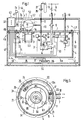
- the compressor 1 contains a compressor 1 with a drive shaft 2 which is coupled to an electric motor 3.
- the motor 3 is arranged in a pressure vessel 4, which has a cover 5 and a wall part 6, which can be fastened to it via a sealing arrangement 29, and has a bottom part 6a.
- the compressor 1, which can be of any design, is sealingly attached to the cover 5 with a housing section 1a and is connected on the suction side to the pressure vessel 4, which can be connected via a suction line 7 to a source of a gas fuel, in the example shown a natural gas line 8 is.
- the suction-side connection of the compressor 1 can be formed by a suction piece 7a, which is sealingly connected to a passage opening 19a provided in the cover 5.
- the pressure side of the compressor 1 is connected on the one hand via a relief line 10 to a switching element 21 arranged in the pressure container 4, which acts in a switching position as a relief valve, and on the other hand can be connected via a feed line 12 to a gas fuel container 13 to be refueled, which in the example shown is a fuel tank not shown vehicle can be formed.
- the suction line 7, which is shown as a e.g. manually operable shut-off device 14 and a filter 9 for separating any impurities contained in the natural gas may also be connected via a check valve 15 to the switching element 21, which acts as an inlet valve in another switching position.
- a differential pressure switch 17, which can be set to a predetermined minimum pressure in the suction line 7, is provided, the first input of which is connected to the suction line 7 and the second input of which is connected to an outflow line 18 leading away from the pressure vessel 4, which is upstream of the differential pressure switch 17 is provided with a safety valve 20 that can be set to a predetermined opening pressure.
- the discharge line 18 is from the immediate vicinity of the refueling device, e.g. beyond a roof covering the facility, led away.
- the check valve 15 can be integrated in the changeover element 21, according to the illustration a 3/2-way valve, which has a first inlet that can be connected to the suction line 7, a second inlet that can be connected to the relief line 10 and an outlet A opening into the interior of the pressure vessel 4 .
- the switching element 21 is connected via an actuator 22, for example a servomotor or, according to FIG. 1, an electromagnet, between an inlet position in which the suction line 7 is connected to the outlet A and the relief line 10 is shut off, and one in FIG. 1 shown relief position adjustable, in which the relief line 10 is connected to the output A and the suction line 7 is shut off.
- a corresponding switching element which is not the subject of the present invention, is known, for example, from Swiss Patent PS 675 459 (P.6364).
- the relief line 10 is provided within the pressure vessel with a high pressure sensor 24 and a pressure relief valve 25 which can be adjusted to a predetermined maximum pressure of the compressed gas fuel and which, as indicated in FIG can have.
- the feed line 12 is provided with shut-off means, which according to the illustration include a e.g. manually operable shut-off device 28 and / or contain a clutch on the compressor side.
- a check valve 27 prevents the gas fuel from flowing back into the feed line 12.
- the differential pressure switch 17 and the high pressure sensor 24 are connected via electrical signal lines 30 and 31 to a control device 32, which via a control line 34 with the actuator 22 of the switching element 21, and via further electrical lines 33 and 35 with the motor 3 or a motor 37 of a blower 36 arranged outside the pressure vessel 4 in the example shown is connected.
- the compressor 1, the motor 3 and the cover 5 are provided with temperature sensors T, which are each connected to the control device 32 via a signal line 38 or 40 or 41.
- the control device 32 is also connected via a signal line 42 to a temperature sensor T1 which detects the ambient temperature and, as shown, is accommodated in a switching unit 43 which can be connected via a power line 44 to a power source (not shown).
- the switching unit 43 can be arranged outside the pressure vessel 4 in a housing 46 which serves for air guidance and which has the wall part 6 and the bottom part 6a surrounding lower part 47 and an upper part 48 surrounding the cover 5 and the compressor 1.
- the lower part 47 is provided in its bottom part with an inlet opening 50, with which the blower 36 is assigned. Cooling air is drawn into the housing 46 by the blower 36, guided against the compressor 1 through an annular space 51 formed between the wall part 6 and the side wall of the housing 46, and discharged from the housing 46 through an outlet opening 52 provided in the upper part 48.
- the refueling device is operated via e.g. switching unit 43 which can be actuated by a key and is operated in a known manner, e.g. described in the above-mentioned EP patent application 0 300 222, via the control device 32 the switching element 21 is adjusted from the switching position shown into the flow position assigned to the suction line 7 and the engine 3 is started. Accordingly, this is from the natural gas line 8 with a pressure of e.g.
- Natural gas supplied at 20 mbar is compressed by the compressor 1 to a predetermined filling pressure and fed to the gas fuel container 13 via the feed line 12, the operating filling pressure being limited via the control device 32 to a value corresponding to the respective ambient temperature as a function of control signals from the temperature sensor T1 and the high-pressure sensor 24 becomes.
- a maximum value of the filling pressure can be set by the pressure limiting valve 25, which e.g. Can be 230 bar.
- the gas fuel supplied from the suction line 7 is passed through the outlet A of the switching member 21 into the pressure vessel 4 containing the fittings and the motor 3 and is sucked out of the latter by the compressor 1.
- the switching device 21 is adjusted via the control device 32 to the flow position shown and assigned to the relief line 10, and the motor 3 is switched off. Accordingly, the compressed gas fuel remaining in the compressor 1 and in the feed line 12 is expanded through the outlet A of the switching element 21 into the pressure vessel 4.
- a pressure of, for example, 2 to 3 is limited by the safety valve 20 built up bar.
- the safety valve 20 is opened and a corresponding amount of the gas fuel is discharged into the open through the outflow line 18, which can be designed with a relatively large diameter and which ensures rapid pressure reduction.
- the pressure vessel 4 can be designed for a relatively low internal pressure which is not significantly higher than the opening pressure set on the safety valve 20. Accordingly, the pressure vessel 4 can be designed in a relatively light, simple design, which in particular requires relatively few flow passages that are easy to seal.
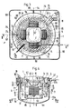
- the compressor can be designed as a two-stage or multi-stage, corresponding to the representation of the refueling device according to FIGS. 2 to 5 as a four-stage piston compressor, the two cylinders 55 and 57, which are arranged opposite one another on a common horizontal axis 53, and two with respect to them by 90 ° offset on a common horizontal axis 54 has an oppositely arranged cylinder 56 and 58, in which pistons, not shown, are guided.
- Each of the piston pairs arranged on the same axis 53 or 54 can be coupled in a known manner via a drive arrangement connecting their piston rods to the vertical drive shaft 2, which is designed as a crankshaft and passes through a central crank chamber 60, the first or the second compression stage, and the third and fourth compression stages can be formed in the cylinders 57 and 58.
- a corresponding compressor the design of which is not the subject of the present invention, is known, for example, from EP patent application 0 389 414 (P.6254).
- the natural gas introduced into the crank chamber 60 with a pressure of, for example, 20 mbar can be sucked into the cylinder 55, for example through a suction opening provided in the piston, compressed to a pressure of, for example, 5 bar and successively in the cylinder 56 to a pressure of, for example, 20 bar , compressed in cylinder 57 to a pressure of, for example, 60 bar and in cylinder 58 to a final pressure of, for example, 200 bar and fed to gas fuel container 13 via feed line 12.
- the compressor 1 is designed with a housing section 1 a which can be placed on the cover 5 of the pressure container 4 and is open towards the interior thereof and which has a cylindrical shoulder 61 which can be inserted into the passage opening 19 of the cover 5.
- the lid 5 of the cylindrical pressure vessel 4 in the embodiment shown is designed with a central collar portion 62 surrounding the passage opening 19, through which the housing portion 1 a is supported and the shoulder 61 is sealingly guided by a sealing arrangement 59.
- the motor 3 with the vertical axis of rotation is arranged in a holder 63 fastened to the cover 5.
- the motor 3 contains a stator part 64 which can be fastened to the holder 63 and a rotor 65 which can be connected to the drive shaft 2 of the compressor 1 via a releasable coupling or which, as indicated in FIG. 4, to the drive shaft 2 at one through the Passage opening 19 is connected to the stator part 63 insertable installation unit. 4, the rotor 65 can be assembled with the compressor 1 and installed in a simple manner by placing and inserting the housing section 1a on or into the collar section 62 and can be correspondingly easily removed by lifting the compressor 1.
- the differential pressure switch 17, the safety valve 20, the switching element 21, the high pressure sensor 24 and the pressure limiting valve 25 are arranged in the annular space formed between the holder 63 and the wall part 6 of the pressure container 4.
- Connections 67 and 68 for the suction line 7 and the outflow line 18 as well as connections 70 and 71 for the relief line 10 and the electrical lines 30, 31, 33, 34 and 35 are provided in the cover 5.
- the connection 67 opens into a bore 72 formed in the cover 5, which serves to receive the filter 9 and which is connected to the through a connection 67a Check valve 15 of the switching element 21 is connected.
- the connection 68 is connected in a manner not shown to the differential pressure switch 17 and the safety valve 20.
- the differential pressure switch 17 and the safety valve 20 can, as shown, be connected to the switching element 21 which can be fastened to the cover 5 to form an installation unit.
- the relief line 10 connected to the cylinder 58 is connected via the connection 70 to the pressure limiting valve 25, which is combined with the high-pressure sensor 24 to form an installation unit which can be fastened to the cover 5 and is connected to the input of the switching element 21 via a line section 10a.
- the pressure limiting valve 25 can also be arranged outside the pressure container 4, inside the compressor housing sealingly connected to it, and connected to a channel 10b which connects the pressure side of the compressor 1 to its suction side.
- the channel 10b is connected to the pressure chamber of the cylinder 58 and closed by the pressure relief valve 25, the outlet A1 of which flows into the pressure tank 4 open crank chamber 60 opens.
- the pressure chamber of the cylinder 58 is furthermore described in the manner described via the relief line 10 with the ones arranged in the pressure vessel 4 and not shown in FIG. 2a Control and monitoring elements - high-pressure sensor 24 and switching element 21 - and can be connected to the gas fuel container 13 via the feed line 12.
- This design can further simplify the structure of the refueling device, in particular with regard to the connections to be provided in the pressure vessel 4.
- the cover 5 of the pressure vessel 4 is supported on supporting parts 76 of the housing 46 which serves for air guidance via three brackets 74 and rubber bearings 75 distributed over its circumference.
- the support parts 76 are formed on the lower part 47, which surrounds the wall part 6 and the cover 5 at a relatively small radial distance and which is connected to an impact plate 77 arranged above the cover 5 and covering the annular space 51 and the edge part of the cover 5.
- the baffle plate 77 can be used to deflect the cooling air flowing through the annular space 51 from the bottom upwards along the cover 5 towards the compressor 1 and to discharge it upwards along the cylinders 55, 56, 57 and 58.
- a guidance of the air flow that is favorable for the cooling of the pressure container 4 and the compressor 1 can be achieved.
- the cover 5 is designed with cooling fins 78 which - seen in the top view according to FIG. 3 - extend from the outer circumference in a spiraling counterclockwise direction to the collar part 62, covering it in the cover 5 by the baffle 77 and in the area of the cylinders 55, 57, 57, 58 limit open air duct 80.
- the cylinders 55, 56, 57 and 58 can be provided with annular cooling fins 81 and with cooling fins 82 running vertically over their end faces, which limit flow paths through which flow can flow in the vertical direction and thus ensure a good cooling effect. As can be seen in particular from FIG.
- the cooling fins 78 of the cover 5 can be curved in an involute manner, the channels 80 each having an essentially constant width over their length, so that the cooling air is guided in an aerodynamic manner and thus an effective cooling of the cover 5 and the compressor 1 can be achieved.
- sufficient cooling can be achieved by means of cooling ribs which are straightforward to produce and are straight, for example arranged in a star shape.
- the blower 36 is supported in the lower part 47 of the housing 46 via a holder, which can contain three support arms 83 connected to the motor 37.
- the switching unit 43 can be accommodated in the form of a control panel which can be provided with pressure switches 84 for actuating the refueling device.
- the housing 46 surrounding the pressure vessel 4 and the compressor 1 can be arranged in a further, outer housing 85, which according to FIG. 3 can be designed with a square cross section.
- the inner housing 46 can be placed over several, for example three consoles 86, on corresponding support parts 87 of the housing 85.
- the outer housing 85 can be connected to the inner housing 46 by partitions 88 be connected, which subdivide the space formed between the housings 85 and 46 into two partial spaces 89 and 90 which can be flowed through one after the other and which are connected to one another only via the lower inlet opening 50 and the opening formed in the baffle wall 77.
- Partial space 89 can be connected to an inlet opening 91 arranged at the upper end of housing 85
- partial space 90 can be connected to an outlet opening 92 arranged at the lower end of housing 85.
- the outer housing 85 can also be provided with a closable cover 93, by means of which the pressure switches 84 can be covered and protected against unauthorized actuation.
- the cooling air is sucked in by the fan 36 according to the arrows L through the inlet opening 91 and the partial space 89, guided according to the arrows L1 along the pressure vessel 4 into the upper part 48 of the inner housing 46 and according to the arrows L2 through the partial space 90 and the outlet opening 92 is led out of the housing 85.
- a cooling air duct is achieved in a confined space, which allows intensive cooling of both the pressure container 4 and the compressor 1 even in the compact construction of the refueling system that can be achieved by the inventive design. Effective noise protection can be achieved at the same time by the housings 46 and 85.
- the complete motor of the compressor can be attached to the inside of the cover 5 designed as a supporting part and connected to the drive shaft of the compressor via a known coupling arrangement arranged in the area of the passage opening 19.
- the compressor and the motor can be inside the pressure container be arranged, whereby a further reduction of sealing points against the environment can be achieved.
- the compressor can be arranged inside and the motor outside the pressure vessel.
- the motor of the compressor can be mounted outside the pressure container, for example inside the housing part of the compressor fastened to the outside of the cover 5 or a corresponding supporting part, the only being used for receiving the fittings - possibly only for the highest pressures Fittings - pressure vessels to be designed can be made correspondingly small.
- another part, for example a bottom part, of the pressure container can also be designed as a supporting part for the compressor and / or the motor.
- guide vane-like guide elements corresponding to the cooling ribs 78 are provided for the cooling air, for example in the housing 46, in particular on the baffle wall 77.
Applications Claiming Priority (2)
| Application Number | Priority Date | Filing Date | Title |
|---|---|---|---|
| CH159391 | 1991-05-30 | ||
| CH1593/91 | 1991-05-30 |
Publications (2)
| Publication Number | Publication Date |
|---|---|
| EP0516580A1 true EP0516580A1 (fr) | 1992-12-02 |
| EP0516580B1 EP0516580B1 (fr) | 1995-03-22 |
Family
ID=4214045
Family Applications (1)
| Application Number | Title | Priority Date | Filing Date |
|---|---|---|---|
| EP92810282A Expired - Lifetime EP0516580B1 (fr) | 1991-05-30 | 1992-04-16 | Dispositif de ravitaillement d'un réservoir à combustible gazeux |
Country Status (6)
| Country | Link |
|---|---|
| US (1) | US5263826A (fr) |
| EP (1) | EP0516580B1 (fr) |
| AU (1) | AU647624B2 (fr) |
| CA (1) | CA2068164C (fr) |
| DE (1) | DE59201707D1 (fr) |
| NZ (1) | NZ242143A (fr) |
Cited By (5)
| Publication number | Priority date | Publication date | Assignee | Title |
|---|---|---|---|---|
| EP2093475A1 (fr) | 2008-02-20 | 2009-08-26 | Air Products and Chemicals, Inc. | Procédé de remplissage de compresseur et appareil |
| EP1447614A3 (fr) * | 2003-02-12 | 2011-04-06 | G.I. & E. S.p.A. | Station de fourniture de gaz comprimé à des réservoirs, en particulier des réservoirs montés sur des véhicules |
| CN102563343A (zh) * | 2010-11-29 | 2012-07-11 | 通用汽车环球科技运作有限责任公司 | 在任何容器压力下均有快速加注燃料能力的压缩气体燃料罐系统 |
| EP3792340A1 (fr) * | 2019-09-04 | 2021-03-17 | XL Beteiligungen GmbH & Co. KG | Réservoir étanche au gaz |
| RU218776U1 (ru) * | 2023-03-21 | 2023-06-09 | Публичное акционерное общество "КАМАЗ" | Устройство для контроля и зарядки гидропневмоаккумулятора газом |
Families Citing this family (17)
| Publication number | Priority date | Publication date | Assignee | Title |
|---|---|---|---|---|
| US5370159A (en) * | 1993-07-19 | 1994-12-06 | Price Compressor Company, Inc. | Apparatus and process for fast filling with natural gas |
| US5501200A (en) * | 1994-06-28 | 1996-03-26 | Bogartz; Stuart P. | Compressed gas fueling system |
| US5957667A (en) * | 1997-05-23 | 1999-09-28 | Ballard Generation Systems Inc. | Oilless compressor with a pressurizable crankcase and motor containment vessel |
| CA2440255A1 (fr) * | 2003-09-09 | 2005-03-09 | Fuelmaker Corporation | Compresseur a gaz avec sechoir et commandes d'emissions radioelectriques |
| AU2003273657A1 (en) * | 2002-10-04 | 2004-04-23 | Fuelmaker Corporation | Gas compressor with drier |
| US7011118B2 (en) * | 2002-10-04 | 2006-03-14 | 2045951 Ontario Inc. | Residential compressor for refueling motor vehicles that operate on gaseous fuels |
| US6899146B2 (en) * | 2003-05-09 | 2005-05-31 | Battelle Energy Alliance, Llc | Method and apparatus for dispensing compressed natural gas and liquified natural gas to natural gas powered vehicles |
| US9618158B2 (en) | 2011-05-02 | 2017-04-11 | New Gas Industries, L.L.C. | Method and apparatus for compressing gas in a plurality of stages to a storage tank array having a plurality of storage tanks |
| SE536423C2 (sv) | 2011-08-16 | 2013-10-22 | Birgit Evermark | Metod och system för produktion av en bild medelst kakel påen vägg, golv eller tak |
| US9765930B2 (en) * | 2012-01-31 | 2017-09-19 | J-W Power Company | CNG fueling system |
| US10018304B2 (en) | 2012-01-31 | 2018-07-10 | J-W Power Company | CNG fueling system |
| US10851944B2 (en) | 2012-01-31 | 2020-12-01 | J-W Power Company | CNG fueling system |
| US20140182561A1 (en) * | 2013-09-25 | 2014-07-03 | Eghosa Gregory Ibizugbe, JR. | Onboard CNG/CFG Vehicle Refueling and Storage Systems and Methods |
| CN103615657A (zh) * | 2013-11-05 | 2014-03-05 | 江苏现代造船技术有限公司 | Lng动力船舶的天然气传输系统 |
| US10634283B2 (en) | 2014-02-21 | 2020-04-28 | Kobe Steel, Ltd. | Gas supply system and hydrogen station |
| US10088109B2 (en) | 2014-11-03 | 2018-10-02 | Gilbarco Inc. | Compressed gas filling method and system |
| US10551001B2 (en) | 2015-09-03 | 2020-02-04 | J-W Power Company | Flow control system |
Citations (2)
| Publication number | Priority date | Publication date | Assignee | Title |
|---|---|---|---|---|
| EP0356377A1 (fr) * | 1988-08-15 | 1990-02-28 | GebràDer Sulzer Aktiengesellschaft | Appareil d'approvisionnement de gaz pour véhicules automobiles |
| CH676951A5 (en) * | 1988-08-12 | 1991-03-28 | Sulzer Ag | Vehicle gas tank filling appliance - has second internal housing for compressor-motor group |
Family Cites Families (4)
| Publication number | Priority date | Publication date | Assignee | Title |
|---|---|---|---|---|
| US2136959A (en) * | 1934-10-26 | 1938-11-15 | Edward A Winfield | Fuel supply system |
| US4700680A (en) * | 1984-05-08 | 1987-10-20 | Teledyne Industries, Inc. | Two stage fuel pump |
| US4799686A (en) * | 1986-12-19 | 1989-01-24 | Martinez Eduardo S | Board game apparatus for a banking game |
| EP0300222B1 (fr) * | 1987-07-23 | 1992-08-12 | GebràDer Sulzer Aktiengesellschaft | Dispositif de ravitaillement d'un réservoir à combustible gazeux |
-
1992
- 1992-03-26 NZ NZ242143A patent/NZ242143A/xx not_active IP Right Cessation
- 1992-03-27 US US07/858,736 patent/US5263826A/en not_active Expired - Lifetime
- 1992-04-16 DE DE59201707T patent/DE59201707D1/de not_active Expired - Lifetime
- 1992-04-16 EP EP92810282A patent/EP0516580B1/fr not_active Expired - Lifetime
- 1992-05-07 CA CA002068164A patent/CA2068164C/fr not_active Expired - Lifetime
- 1992-05-29 AU AU17289/92A patent/AU647624B2/en not_active Expired
Patent Citations (2)
| Publication number | Priority date | Publication date | Assignee | Title |
|---|---|---|---|---|
| CH676951A5 (en) * | 1988-08-12 | 1991-03-28 | Sulzer Ag | Vehicle gas tank filling appliance - has second internal housing for compressor-motor group |
| EP0356377A1 (fr) * | 1988-08-15 | 1990-02-28 | GebràDer Sulzer Aktiengesellschaft | Appareil d'approvisionnement de gaz pour véhicules automobiles |
Cited By (7)
| Publication number | Priority date | Publication date | Assignee | Title |
|---|---|---|---|---|
| EP1447614A3 (fr) * | 2003-02-12 | 2011-04-06 | G.I. & E. S.p.A. | Station de fourniture de gaz comprimé à des réservoirs, en particulier des réservoirs montés sur des véhicules |
| EP2093475A1 (fr) | 2008-02-20 | 2009-08-26 | Air Products and Chemicals, Inc. | Procédé de remplissage de compresseur et appareil |
| US8365777B2 (en) | 2008-02-20 | 2013-02-05 | Air Products And Chemicals, Inc. | Compressor fill method and apparatus |
| CN102563343A (zh) * | 2010-11-29 | 2012-07-11 | 通用汽车环球科技运作有限责任公司 | 在任何容器压力下均有快速加注燃料能力的压缩气体燃料罐系统 |
| CN102563343B (zh) * | 2010-11-29 | 2015-10-14 | 通用汽车环球科技运作有限责任公司 | 在任何容器压力下均有快速加注燃料能力的压缩气体燃料罐系统 |
| EP3792340A1 (fr) * | 2019-09-04 | 2021-03-17 | XL Beteiligungen GmbH & Co. KG | Réservoir étanche au gaz |
| RU218776U1 (ru) * | 2023-03-21 | 2023-06-09 | Публичное акционерное общество "КАМАЗ" | Устройство для контроля и зарядки гидропневмоаккумулятора газом |
Also Published As
| Publication number | Publication date |
|---|---|
| AU1728992A (en) | 1992-12-03 |
| CA2068164A1 (fr) | 1992-12-01 |
| US5263826A (en) | 1993-11-23 |
| AU647624B2 (en) | 1994-03-24 |
| NZ242143A (en) | 1994-03-25 |
| EP0516580B1 (fr) | 1995-03-22 |
| DE59201707D1 (de) | 1995-04-27 |
| CA2068164C (fr) | 2003-04-08 |
Similar Documents
| Publication | Publication Date | Title |
|---|---|---|
| EP0516580B1 (fr) | Dispositif de ravitaillement d'un réservoir à combustible gazeux | |
| EP0300222B1 (fr) | Dispositif de ravitaillement d'un réservoir à combustible gazeux | |
| EP0920587B1 (fr) | Compresseur frigorifique | |
| DE102017122327B4 (de) | Spiralverdichter | |
| DE2824401A1 (de) | Turboladersteuerung | |
| DE102006024816A1 (de) | Einrichtung für die Entlüftung eines Kurbelgehäuses | |
| WO1998048165A1 (fr) | Systeme d'injection de carburant pour moteur a combustion interne a systeme d'injection par accumulation de pression | |
| EP3477167B1 (fr) | Module de gestion thermique | |
| EP3298241A1 (fr) | Pompe à vide à palettes lubrifiée à l'huile munie d'un dispositif de séparation et de recyclage de l'huile | |
| EP1090231A1 (fr) | Pompe a vide rotative munie d'un chassis, d'un rotor et d'un carter, et dispositif pourvu d'une pompe a vide rotative de ce type | |
| DE102010055316B4 (de) | Einrichtung zur Entlüftung und Belüftung eines Kraftstofftanks | |
| DE10308420A1 (de) | Testgaslecksuchgerät | |
| EP1240433B1 (fr) | Pompe à vide à compression sèche comportant un dispositif de ballast à gaz | |
| DE3344765A1 (de) | Tauchpumpe | |
| DE19717799C2 (de) | Baueinheit für eine Kompaktheizungsanlage | |
| DE2400325A1 (de) | Mit oeleinspritzung arbeitender kreiselkompressor | |
| DE3841097A1 (de) | Ansaugeinrichtung fuer die verbrennungsluft eines kraftfahrzeug-frontmotors | |
| DE102016225923A1 (de) | Pumpenaggregat für ein Hydrauliksystem und Kanalelement für ein Pumpenaggregat | |
| DE102016011394A1 (de) | Schraubenkompressor für ein Nutzfahrzeug | |
| EP0793017B1 (fr) | Pompe pour appareil de nettoyage à haute pression | |
| DE3517493A1 (de) | In einem kompakten gehaeuse angeordnete schraubenverdichter-anlage | |
| WO1997049916A1 (fr) | Pompe d'alimentation en carburant pour pompe d'injection de carburant pour moteurs a combustion interne | |
| DE10303303A1 (de) | Hochdruck-Kraftstoffpumpe | |
| EP0201672A2 (fr) | Compresseur à vis à construction compacte | |
| EP0249657B1 (fr) | Dispositif comportant une pompe à palettes |
Legal Events
| Date | Code | Title | Description |
|---|---|---|---|
| PUAI | Public reference made under article 153(3) epc to a published international application that has entered the european phase |
Free format text: ORIGINAL CODE: 0009012 |
|
| AK | Designated contracting states |
Kind code of ref document: A1 Designated state(s): CH DE FR GB IT LI NL |
|
| 17P | Request for examination filed |
Effective date: 19930423 |
|
| 17Q | First examination report despatched |
Effective date: 19940412 |
|
| RAP1 | Party data changed (applicant data changed or rights of an application transferred) |
Owner name: MASCHINENFABRIK SULZER-BURCKHARDT AG |
|
| GRAA | (expected) grant |
Free format text: ORIGINAL CODE: 0009210 |
|
| AK | Designated contracting states |
Kind code of ref document: B1 Designated state(s): CH DE FR GB IT LI NL |
|
| ET | Fr: translation filed | ||
| GBT | Gb: translation of ep patent filed (gb section 77(6)(a)/1977) |
Effective date: 19950327 |
|
| REF | Corresponds to: |
Ref document number: 59201707 Country of ref document: DE Date of ref document: 19950427 |
|
| ITF | It: translation for a ep patent filed |
Owner name: ING. ZINI MARANESI & C. S.R.L. |
|
| PLBE | No opposition filed within time limit |
Free format text: ORIGINAL CODE: 0009261 |
|
| STAA | Information on the status of an ep patent application or granted ep patent |
Free format text: STATUS: NO OPPOSITION FILED WITHIN TIME LIMIT |
|
| 26N | No opposition filed | ||
| REG | Reference to a national code |
Ref country code: CH Ref legal event code: PUE Owner name: MASCHINENFABRIK SULZER-BURCKHARDT AG TRANSFER- GRE |
|
| REG | Reference to a national code |
Ref country code: GB Ref legal event code: 732E |
|
| NLS | Nl: assignments of ep-patents |
Owner name: GREENFIELD AG |
|
| REG | Reference to a national code |
Ref country code: FR Ref legal event code: TP |
|
| REG | Reference to a national code |
Ref country code: GB Ref legal event code: IF02 |
|
| PGFP | Annual fee paid to national office [announced via postgrant information from national office to epo] |
Ref country code: DE Payment date: 20110421 Year of fee payment: 20 Ref country code: CH Payment date: 20110428 Year of fee payment: 20 Ref country code: FR Payment date: 20110510 Year of fee payment: 20 |
|
| PGFP | Annual fee paid to national office [announced via postgrant information from national office to epo] |
Ref country code: NL Payment date: 20110426 Year of fee payment: 20 Ref country code: GB Payment date: 20110421 Year of fee payment: 20 |
|
| PGFP | Annual fee paid to national office [announced via postgrant information from national office to epo] |
Ref country code: IT Payment date: 20110422 Year of fee payment: 20 |
|
| REG | Reference to a national code |
Ref country code: DE Ref legal event code: R071 Ref document number: 59201707 Country of ref document: DE |
|
| REG | Reference to a national code |
Ref country code: DE Ref legal event code: R071 Ref document number: 59201707 Country of ref document: DE |
|
| REG | Reference to a national code |
Ref country code: NL Ref legal event code: V4 Effective date: 20120416 |
|
| REG | Reference to a national code |
Ref country code: CH Ref legal event code: PL |
|
| REG | Reference to a national code |
Ref country code: GB Ref legal event code: PE20 Expiry date: 20120415 |
|
| PG25 | Lapsed in a contracting state [announced via postgrant information from national office to epo] |
Ref country code: DE Free format text: LAPSE BECAUSE OF EXPIRATION OF PROTECTION Effective date: 20120417 |
|
| PG25 | Lapsed in a contracting state [announced via postgrant information from national office to epo] |
Ref country code: GB Free format text: LAPSE BECAUSE OF EXPIRATION OF PROTECTION Effective date: 20120415 |