EP0516580A1 - Filling device for a gaseous fuel tank - Google Patents
Filling device for a gaseous fuel tank Download PDFInfo
- Publication number
- EP0516580A1 EP0516580A1 EP92810282A EP92810282A EP0516580A1 EP 0516580 A1 EP0516580 A1 EP 0516580A1 EP 92810282 A EP92810282 A EP 92810282A EP 92810282 A EP92810282 A EP 92810282A EP 0516580 A1 EP0516580 A1 EP 0516580A1
- Authority
- EP
- European Patent Office
- Prior art keywords
- pressure
- compressor
- pressure vessel
- line
- housing
- Prior art date
- Legal status (The legal status is an assumption and is not a legal conclusion. Google has not performed a legal analysis and makes no representation as to the accuracy of the status listed.)
- Granted
Links
- 239000002828 fuel tank Substances 0.000 title claims description 3
- 239000007789 gas Substances 0.000 claims abstract description 25
- 239000000446 fuel Substances 0.000 claims abstract description 22
- VNWKTOKETHGBQD-UHFFFAOYSA-N methane Chemical compound C VNWKTOKETHGBQD-UHFFFAOYSA-N 0.000 claims abstract description 16
- 239000003345 natural gas Substances 0.000 claims abstract description 8
- 238000001816 cooling Methods 0.000 claims description 26
- 238000012544 monitoring process Methods 0.000 claims description 8
- 238000009434 installation Methods 0.000 claims description 6
- 238000005192 partition Methods 0.000 claims description 2
- 230000000149 penetrating effect Effects 0.000 claims 1
- 238000007789 sealing Methods 0.000 description 5
- 230000006835 compression Effects 0.000 description 2
- 238000007906 compression Methods 0.000 description 2
- 238000010276 construction Methods 0.000 description 2
- 230000008878 coupling Effects 0.000 description 2
- 238000010168 coupling process Methods 0.000 description 2
- 238000005859 coupling reaction Methods 0.000 description 2
- 238000007689 inspection Methods 0.000 description 2
- 238000012423 maintenance Methods 0.000 description 2
- 230000003111 delayed effect Effects 0.000 description 1
- 230000001419 dependent effect Effects 0.000 description 1
- 238000010586 diagram Methods 0.000 description 1
- 230000000694 effects Effects 0.000 description 1
- 230000002349 favourable effect Effects 0.000 description 1
- 239000012535 impurity Substances 0.000 description 1
- 230000000717 retained effect Effects 0.000 description 1
- 238000011144 upstream manufacturing Methods 0.000 description 1
Images

Classifications
-
- F—MECHANICAL ENGINEERING; LIGHTING; HEATING; WEAPONS; BLASTING
- F17—STORING OR DISTRIBUTING GASES OR LIQUIDS
- F17C—VESSELS FOR CONTAINING OR STORING COMPRESSED, LIQUEFIED OR SOLIDIFIED GASES; FIXED-CAPACITY GAS-HOLDERS; FILLING VESSELS WITH, OR DISCHARGING FROM VESSELS, COMPRESSED, LIQUEFIED, OR SOLIDIFIED GASES
- F17C5/00—Methods or apparatus for filling containers with liquefied, solidified, or compressed gases under pressures
- F17C5/002—Automated filling apparatus
- F17C5/007—Automated filling apparatus for individual gas tanks or containers, e.g. in vehicles
-
- B—PERFORMING OPERATIONS; TRANSPORTING
- B60—VEHICLES IN GENERAL
- B60S—SERVICING, CLEANING, REPAIRING, SUPPORTING, LIFTING, OR MANOEUVRING OF VEHICLES, NOT OTHERWISE PROVIDED FOR
- B60S5/00—Servicing, maintaining, repairing, or refitting of vehicles
- B60S5/02—Supplying fuel to vehicles; General disposition of plant in filling stations
-
- F—MECHANICAL ENGINEERING; LIGHTING; HEATING; WEAPONS; BLASTING
- F02—COMBUSTION ENGINES; HOT-GAS OR COMBUSTION-PRODUCT ENGINE PLANTS
- F02B—INTERNAL-COMBUSTION PISTON ENGINES; COMBUSTION ENGINES IN GENERAL
- F02B43/00—Engines characterised by operating on gaseous fuels; Plants including such engines
-
- F—MECHANICAL ENGINEERING; LIGHTING; HEATING; WEAPONS; BLASTING
- F17—STORING OR DISTRIBUTING GASES OR LIQUIDS
- F17C—VESSELS FOR CONTAINING OR STORING COMPRESSED, LIQUEFIED OR SOLIDIFIED GASES; FIXED-CAPACITY GAS-HOLDERS; FILLING VESSELS WITH, OR DISCHARGING FROM VESSELS, COMPRESSED, LIQUEFIED, OR SOLIDIFIED GASES
- F17C2205/00—Vessel construction, in particular mounting arrangements, attachments or identifications means
- F17C2205/01—Mounting arrangements
- F17C2205/0103—Exterior arrangements
- F17C2205/0111—Boxes
-
- F—MECHANICAL ENGINEERING; LIGHTING; HEATING; WEAPONS; BLASTING
- F17—STORING OR DISTRIBUTING GASES OR LIQUIDS
- F17C—VESSELS FOR CONTAINING OR STORING COMPRESSED, LIQUEFIED OR SOLIDIFIED GASES; FIXED-CAPACITY GAS-HOLDERS; FILLING VESSELS WITH, OR DISCHARGING FROM VESSELS, COMPRESSED, LIQUEFIED, OR SOLIDIFIED GASES
- F17C2205/00—Vessel construction, in particular mounting arrangements, attachments or identifications means
- F17C2205/03—Fluid connections, filters, valves, closure means or other attachments
- F17C2205/0302—Fittings, valves, filters, or components in connection with the gas storage device
- F17C2205/0323—Valves
- F17C2205/0329—Valves manually actuated
-
- F—MECHANICAL ENGINEERING; LIGHTING; HEATING; WEAPONS; BLASTING
- F17—STORING OR DISTRIBUTING GASES OR LIQUIDS
- F17C—VESSELS FOR CONTAINING OR STORING COMPRESSED, LIQUEFIED OR SOLIDIFIED GASES; FIXED-CAPACITY GAS-HOLDERS; FILLING VESSELS WITH, OR DISCHARGING FROM VESSELS, COMPRESSED, LIQUEFIED, OR SOLIDIFIED GASES
- F17C2205/00—Vessel construction, in particular mounting arrangements, attachments or identifications means
- F17C2205/03—Fluid connections, filters, valves, closure means or other attachments
- F17C2205/0302—Fittings, valves, filters, or components in connection with the gas storage device
- F17C2205/0323—Valves
- F17C2205/0332—Safety valves or pressure relief valves
-
- F—MECHANICAL ENGINEERING; LIGHTING; HEATING; WEAPONS; BLASTING
- F17—STORING OR DISTRIBUTING GASES OR LIQUIDS
- F17C—VESSELS FOR CONTAINING OR STORING COMPRESSED, LIQUEFIED OR SOLIDIFIED GASES; FIXED-CAPACITY GAS-HOLDERS; FILLING VESSELS WITH, OR DISCHARGING FROM VESSELS, COMPRESSED, LIQUEFIED, OR SOLIDIFIED GASES
- F17C2205/00—Vessel construction, in particular mounting arrangements, attachments or identifications means
- F17C2205/03—Fluid connections, filters, valves, closure means or other attachments
- F17C2205/0302—Fittings, valves, filters, or components in connection with the gas storage device
- F17C2205/0323—Valves
- F17C2205/0335—Check-valves or non-return valves
-
- F—MECHANICAL ENGINEERING; LIGHTING; HEATING; WEAPONS; BLASTING
- F17—STORING OR DISTRIBUTING GASES OR LIQUIDS
- F17C—VESSELS FOR CONTAINING OR STORING COMPRESSED, LIQUEFIED OR SOLIDIFIED GASES; FIXED-CAPACITY GAS-HOLDERS; FILLING VESSELS WITH, OR DISCHARGING FROM VESSELS, COMPRESSED, LIQUEFIED, OR SOLIDIFIED GASES
- F17C2205/00—Vessel construction, in particular mounting arrangements, attachments or identifications means
- F17C2205/03—Fluid connections, filters, valves, closure means or other attachments
- F17C2205/0302—Fittings, valves, filters, or components in connection with the gas storage device
- F17C2205/0338—Pressure regulators
-
- F—MECHANICAL ENGINEERING; LIGHTING; HEATING; WEAPONS; BLASTING
- F17—STORING OR DISTRIBUTING GASES OR LIQUIDS
- F17C—VESSELS FOR CONTAINING OR STORING COMPRESSED, LIQUEFIED OR SOLIDIFIED GASES; FIXED-CAPACITY GAS-HOLDERS; FILLING VESSELS WITH, OR DISCHARGING FROM VESSELS, COMPRESSED, LIQUEFIED, OR SOLIDIFIED GASES
- F17C2205/00—Vessel construction, in particular mounting arrangements, attachments or identifications means
- F17C2205/03—Fluid connections, filters, valves, closure means or other attachments
- F17C2205/0302—Fittings, valves, filters, or components in connection with the gas storage device
- F17C2205/0341—Filters
-
- F—MECHANICAL ENGINEERING; LIGHTING; HEATING; WEAPONS; BLASTING
- F17—STORING OR DISTRIBUTING GASES OR LIQUIDS
- F17C—VESSELS FOR CONTAINING OR STORING COMPRESSED, LIQUEFIED OR SOLIDIFIED GASES; FIXED-CAPACITY GAS-HOLDERS; FILLING VESSELS WITH, OR DISCHARGING FROM VESSELS, COMPRESSED, LIQUEFIED, OR SOLIDIFIED GASES
- F17C2221/00—Handled fluid, in particular type of fluid
- F17C2221/03—Mixtures
- F17C2221/032—Hydrocarbons
- F17C2221/033—Methane, e.g. natural gas, CNG, LNG, GNL, GNC, PLNG
-
- F—MECHANICAL ENGINEERING; LIGHTING; HEATING; WEAPONS; BLASTING
- F17—STORING OR DISTRIBUTING GASES OR LIQUIDS
- F17C—VESSELS FOR CONTAINING OR STORING COMPRESSED, LIQUEFIED OR SOLIDIFIED GASES; FIXED-CAPACITY GAS-HOLDERS; FILLING VESSELS WITH, OR DISCHARGING FROM VESSELS, COMPRESSED, LIQUEFIED, OR SOLIDIFIED GASES
- F17C2223/00—Handled fluid before transfer, i.e. state of fluid when stored in the vessel or before transfer from the vessel
- F17C2223/01—Handled fluid before transfer, i.e. state of fluid when stored in the vessel or before transfer from the vessel characterised by the phase
- F17C2223/0107—Single phase
- F17C2223/0123—Single phase gaseous, e.g. CNG, GNC
-
- F—MECHANICAL ENGINEERING; LIGHTING; HEATING; WEAPONS; BLASTING
- F17—STORING OR DISTRIBUTING GASES OR LIQUIDS
- F17C—VESSELS FOR CONTAINING OR STORING COMPRESSED, LIQUEFIED OR SOLIDIFIED GASES; FIXED-CAPACITY GAS-HOLDERS; FILLING VESSELS WITH, OR DISCHARGING FROM VESSELS, COMPRESSED, LIQUEFIED, OR SOLIDIFIED GASES
- F17C2223/00—Handled fluid before transfer, i.e. state of fluid when stored in the vessel or before transfer from the vessel
- F17C2223/03—Handled fluid before transfer, i.e. state of fluid when stored in the vessel or before transfer from the vessel characterised by the pressure level
- F17C2223/036—Very high pressure (>80 bar)
-
- F—MECHANICAL ENGINEERING; LIGHTING; HEATING; WEAPONS; BLASTING
- F17—STORING OR DISTRIBUTING GASES OR LIQUIDS
- F17C—VESSELS FOR CONTAINING OR STORING COMPRESSED, LIQUEFIED OR SOLIDIFIED GASES; FIXED-CAPACITY GAS-HOLDERS; FILLING VESSELS WITH, OR DISCHARGING FROM VESSELS, COMPRESSED, LIQUEFIED, OR SOLIDIFIED GASES
- F17C2227/00—Transfer of fluids, i.e. method or means for transferring the fluid; Heat exchange with the fluid
- F17C2227/01—Propulsion of the fluid
- F17C2227/0128—Propulsion of the fluid with pumps or compressors
- F17C2227/0157—Compressors
-
- F—MECHANICAL ENGINEERING; LIGHTING; HEATING; WEAPONS; BLASTING
- F17—STORING OR DISTRIBUTING GASES OR LIQUIDS
- F17C—VESSELS FOR CONTAINING OR STORING COMPRESSED, LIQUEFIED OR SOLIDIFIED GASES; FIXED-CAPACITY GAS-HOLDERS; FILLING VESSELS WITH, OR DISCHARGING FROM VESSELS, COMPRESSED, LIQUEFIED, OR SOLIDIFIED GASES
- F17C2227/00—Transfer of fluids, i.e. method or means for transferring the fluid; Heat exchange with the fluid
- F17C2227/03—Heat exchange with the fluid
- F17C2227/0337—Heat exchange with the fluid by cooling
- F17C2227/0341—Heat exchange with the fluid by cooling using another fluid
- F17C2227/0344—Air cooling
- F17C2227/0346—Air cooling by forced circulation, e.g. using a fan
-
- F—MECHANICAL ENGINEERING; LIGHTING; HEATING; WEAPONS; BLASTING
- F17—STORING OR DISTRIBUTING GASES OR LIQUIDS
- F17C—VESSELS FOR CONTAINING OR STORING COMPRESSED, LIQUEFIED OR SOLIDIFIED GASES; FIXED-CAPACITY GAS-HOLDERS; FILLING VESSELS WITH, OR DISCHARGING FROM VESSELS, COMPRESSED, LIQUEFIED, OR SOLIDIFIED GASES
- F17C2250/00—Accessories; Control means; Indicating, measuring or monitoring of parameters
- F17C2250/04—Indicating or measuring of parameters as input values
- F17C2250/0404—Parameters indicated or measured
- F17C2250/043—Pressure
-
- F—MECHANICAL ENGINEERING; LIGHTING; HEATING; WEAPONS; BLASTING
- F17—STORING OR DISTRIBUTING GASES OR LIQUIDS
- F17C—VESSELS FOR CONTAINING OR STORING COMPRESSED, LIQUEFIED OR SOLIDIFIED GASES; FIXED-CAPACITY GAS-HOLDERS; FILLING VESSELS WITH, OR DISCHARGING FROM VESSELS, COMPRESSED, LIQUEFIED, OR SOLIDIFIED GASES
- F17C2250/00—Accessories; Control means; Indicating, measuring or monitoring of parameters
- F17C2250/04—Indicating or measuring of parameters as input values
- F17C2250/0404—Parameters indicated or measured
- F17C2250/0439—Temperature
-
- F—MECHANICAL ENGINEERING; LIGHTING; HEATING; WEAPONS; BLASTING
- F17—STORING OR DISTRIBUTING GASES OR LIQUIDS
- F17C—VESSELS FOR CONTAINING OR STORING COMPRESSED, LIQUEFIED OR SOLIDIFIED GASES; FIXED-CAPACITY GAS-HOLDERS; FILLING VESSELS WITH, OR DISCHARGING FROM VESSELS, COMPRESSED, LIQUEFIED, OR SOLIDIFIED GASES
- F17C2250/00—Accessories; Control means; Indicating, measuring or monitoring of parameters
- F17C2250/06—Controlling or regulating of parameters as output values
- F17C2250/0605—Parameters
- F17C2250/0626—Pressure
-
- F—MECHANICAL ENGINEERING; LIGHTING; HEATING; WEAPONS; BLASTING
- F17—STORING OR DISTRIBUTING GASES OR LIQUIDS
- F17C—VESSELS FOR CONTAINING OR STORING COMPRESSED, LIQUEFIED OR SOLIDIFIED GASES; FIXED-CAPACITY GAS-HOLDERS; FILLING VESSELS WITH, OR DISCHARGING FROM VESSELS, COMPRESSED, LIQUEFIED, OR SOLIDIFIED GASES
- F17C2265/00—Effects achieved by gas storage or gas handling
- F17C2265/06—Fluid distribution
- F17C2265/065—Fluid distribution for refueling vehicle fuel tanks
-
- F—MECHANICAL ENGINEERING; LIGHTING; HEATING; WEAPONS; BLASTING
- F17—STORING OR DISTRIBUTING GASES OR LIQUIDS
- F17C—VESSELS FOR CONTAINING OR STORING COMPRESSED, LIQUEFIED OR SOLIDIFIED GASES; FIXED-CAPACITY GAS-HOLDERS; FILLING VESSELS WITH, OR DISCHARGING FROM VESSELS, COMPRESSED, LIQUEFIED, OR SOLIDIFIED GASES
- F17C2270/00—Applications
- F17C2270/01—Applications for fluid transport or storage
- F17C2270/0134—Applications for fluid transport or storage placed above the ground
- F17C2270/0139—Fuel stations
-
- Y—GENERAL TAGGING OF NEW TECHNOLOGICAL DEVELOPMENTS; GENERAL TAGGING OF CROSS-SECTIONAL TECHNOLOGIES SPANNING OVER SEVERAL SECTIONS OF THE IPC; TECHNICAL SUBJECTS COVERED BY FORMER USPC CROSS-REFERENCE ART COLLECTIONS [XRACs] AND DIGESTS
- Y02—TECHNOLOGIES OR APPLICATIONS FOR MITIGATION OR ADAPTATION AGAINST CLIMATE CHANGE
- Y02T—CLIMATE CHANGE MITIGATION TECHNOLOGIES RELATED TO TRANSPORTATION
- Y02T10/00—Road transport of goods or passengers
- Y02T10/10—Internal combustion engine [ICE] based vehicles
- Y02T10/30—Use of alternative fuels, e.g. biofuels
Landscapes
- Engineering & Computer Science (AREA)
- Mechanical Engineering (AREA)
- General Engineering & Computer Science (AREA)
- Chemical & Material Sciences (AREA)
- Combustion & Propulsion (AREA)
- Chemical Kinetics & Catalysis (AREA)
- General Chemical & Material Sciences (AREA)
- Oil, Petroleum & Natural Gas (AREA)
- Filling Or Discharging Of Gas Storage Vessels (AREA)
- Compressor (AREA)
- Compressors, Vaccum Pumps And Other Relevant Systems (AREA)
Abstract
Ein Kompressor (1) ist saugseitig über eine mit einem Einlassventil (16) versehene Saugleitung (7) an eine Erdgasleitung (9), und druckseitig über eine Speiseleitung (12) an den Gasbrennstoffbehälter (13) anschliessbar sowie über eine Entlastungsleitung (10) mit einem Entlastungsventil (11) und einem Druckbegrenzungsventil (25) verbunden, welche Ventile in einem Druckbehälter (4) angeordnet sind. Dieser ist mit der Saugseite des Kompressors (1) und den Ausgangsseiten des Einlassventils (16) und des Entlastungsventils (11) sowie über ein auf einen vorbestimmten Oeffnungsdruck von z.B. 2 bis 3 bar einstellbares Sicherheitsventil (20) mit einer Abströmleitung (18) verbunden. Der Druckbehälter (4) ist mit einem als Tragteil ausgebildeten Deckel (5) ausgeführt, auf dem der Kompressor (1) angebracht ist. Der Kompressor (1) ist über eine vertikale Antriebswelle (2) mit einem innerhalb des Druckbehälters (4) angeordneten Motor (3) kuppelbar. Diese Anordnung ermöglicht eine einfache Ausführung des Druckbehälters (4) und eine kompakte Bauweise der insbesondere zum Betanken von Kraftfahrzeugen bestimmten Einrichtung. <IMAGE>A compressor (1) can be connected on the suction side via a suction line (7) provided with an inlet valve (16) to a natural gas line (9), and on the pressure side via a feed line (12) to the gas fuel container (13) as well as via a relief line (10) a relief valve (11) and a pressure relief valve (25) connected, which valves are arranged in a pressure vessel (4). This is connected to the suction side of the compressor (1) and the outlet sides of the inlet valve (16) and the relief valve (11) as well as to a predetermined opening pressure of e.g. 2 to 3 bar adjustable safety valve (20) connected to an outflow line (18). The pressure vessel (4) is designed with a cover (5) designed as a supporting part, on which the compressor (1) is attached. The compressor (1) can be coupled via a vertical drive shaft (2) to a motor (3) arranged inside the pressure container (4). This arrangement enables a simple design of the pressure container (4) and a compact design of the device intended in particular for refueling motor vehicles. <IMAGE>
Description
Die Erfindung betrifft eine Einrichtung zum Betanken eines Gasbrennstoffbehälters, mit einem über einen elektrischen Motor antreibbaren Kompressor, dessen Saugseite über eine mit einem Einlassventil versehene Saugleitung an eine Quelle des Gasbrennstoffs, insbesondere eine Erdgasleitung, anschliessbar ist und dessen Druckseite an eine mit dem zu betankenden Gasbrennstoffbehälter kuppelbare Speiseleitung anschliessbar ist und über Steuer- und Ueberwachungselemente, welche ein in einem Druckraum eines Druckbehälters angeordnetes Entlastungsventil und ein auf einen vorbestimmten Oeffnungsdruck einstellbares Sicherheitsventil enthalten, mit einer aus dem Druckbehälter wegführenden Abströmleitung in Verbindung steht.The invention relates to a device for refueling a gas fuel container, with a compressor which can be driven by an electric motor, the suction side of which can be connected to a source of the gas fuel, in particular a natural gas line, via a suction line provided with an inlet valve, and the pressure side of which can be connected to a gas fuel container to be refueled detachable feed line can be connected and is connected via control and monitoring elements which contain a relief valve arranged in a pressure chamber of a pressure vessel and a safety valve which can be set to a predetermined opening pressure, with an outflow line leading away from the pressure vessel.
Bei einer aus der EP-Patentanmeldung 0 300 222 bekannten Einrichtung der genannten Art, mit einem Kompressor, dessen Fülldruck über eine Steuereinrichtung in Abhängigkeit von der Umgebungstemperatur beeinflussbar ist, sind der Kompressor und der Motor neben dem Druckbehälter angeordnet, welcher durch eine Zwischenwand in einen mit der Druckseite des Kompressors verbundenen Armaturenraum und einen mit der Saugseite des Kompressors verbundenen Pufferraum unterteilt ist. Der Armaturenraum enthält das Einlassventil, das Entlastungsventil, ein Druckbegrenzungsventil und weitere Armaturen, wobei das Einlassventil und das Entlastungsventil durch ein gemeinsames Umschaltorgan gebildet sein können. Der Pufferraum ist über in der Zwischenwand ausgebildete Verbindungskanäle mit den Austrittsseiten des Einlassventils und des Entlastungsventils verbunden und über ein auf einen relativ niederen Oeffnungsdruck, z.B. 2 bis 3 bar, einstellbares Sicherheitsventil mit dem Armaturenraum verbindbar, an den die Abströmleitung anschliesst. Beim Erreichen eines vorbestimmten, der Umgebungstemperatur angepassten Fülldrucks, der z.B. 100 bis 200 bar betragen kann, wird bei der bekannten Einrichtung über die Steuereinrichtung der Motor des Kompressors abgeschaltet und das Entlastungsventil geöffnet, wobei die im Kompressor und in der Speiseleitung verbliebene, verdichtete Gasbrennstoffmenge in den Pufferraum, und beim Ueberschreiten des durch das Sicherheitsventil begrenzten Drucks, in den Armaturenraum geführt und aus diesem, durch eine Drosselstelle verzögert, über die Abströmleitung abgeführt wird. In entsprechender Weise wird auch bei einem Ueberschreiten eines am Druckbegrenzungsventil eingestellten Höchstwertes des Fülldrucks die in den Armaturenraum austretende Gasmenge über die Abströmleitung abgeführt.In a device of the type mentioned, which is known from EP patent application 0 300 222, with a compressor, the filling pressure of which can be influenced via a control device as a function of the ambient temperature, the compressor and the motor are arranged next to the pressure vessel, which is separated into one by an intermediate wall valve compartment connected to the pressure side of the compressor and one connected to the suction side of the compressor Buffer space is divided. The valve compartment contains the inlet valve, the relief valve, a pressure relief valve and further fittings, wherein the inlet valve and the relief valve can be formed by a common switching element. The buffer chamber is connected to the outlet sides of the inlet valve and the relief valve via connecting channels formed in the intermediate wall and can be connected to the valve chamber to which the outflow line connects via a safety valve that can be set to a relatively low opening pressure, for example 2 to 3 bar. When a predetermined filling pressure, which is adapted to the ambient temperature and can be, for example, 100 to 200 bar, is reached, in the known device the motor of the compressor is switched off via the control device and the relief valve is opened, the compressed gas quantity remaining in the compressor and in the feed line in the buffer space, and when the pressure limited by the safety valve is exceeded, is led into the valve space and is discharged from it via the outflow line, delayed by a throttle point. In a corresponding manner, even if a maximum value of the filling pressure set at the pressure limiting valve is exceeded, the gas quantity escaping into the valve compartment is discharged via the outflow line.
Die bekannte Einrichtung erfordert einen relativ grossen Platzbedarf für die nebeneinander anzuordnenden und miteinander zu verbindenden Aggregate und eine konstruktiv relativ aufwendige Ausführung des zwei druckdichte, explosionsfeste Behälterteile aufweisenden Druckbehälters mit der als Verbindungsteil, insbesondere als Verteilblock ausgebildeten Zwischenwand.The known device requires a relatively large amount of space for the units to be arranged side by side and to be connected to one another and a structurally relatively complex design of the pressure container having two pressure-tight, explosion-proof container parts with the intermediate wall designed as a connecting part, in particular as a distribution block.
Der Erfindung liegt die Aufgabe zugrunde, eine insbesondere in dieser Hinsicht weiter entwickelte Betankungseinrichtung der eingangs genannten Art in einer kompakten Ausführung zu schaffen, in welcher der Kompressor, der Motor, der Druckbehälter und die erforderlichen Steuerungs- und Ueberwachungselemente zu einer mit geringem Aufwand als Ganzes transportierbaren und einfach installierbaren Baueinheit zusammengefasst sind und welche mit einem vereinfachten Druckbehälter mindestens die gleiche Betriebssicherheit wie die bekannte Einrichtung gewährleistet.The invention has for its object to provide a refueling device of the type mentioned in a compact design, in which the compressor, the motor, the pressure vessel and the necessary control and monitoring elements all in one with little effort as a whole Transportable and easy to install unit are summarized and which ensures at least the same operational reliability as the known device with a simplified pressure vessel.
Diese Aufgabe wird erfindungsgemäss dadurch gelöst, dass die Saugseite des Kompressors und die Saugleitung an den das Entlastungsventil und das Sicherheitsventil enthaltenden Druckraum des Druckbehälters angeschlossen sind, dass die Abströmleitung über das Sicherheitsventil an diesen Druckraum angeschlossen ist, und dass ein Teil des Druckbehälters als Tragteil für eine an diesem anbringbare Gehäusepartie des Kompressors ausgebildet ist.According to the invention, this object is achieved in that the suction side of the compressor and the suction line are connected to the pressure chamber of the pressure container containing the relief valve and the safety valve, that the outflow line is connected to this pressure chamber via the safety valve, and that part of the pressure container is used as a supporting part for a housing part of the compressor which can be attached to this is formed.
Durch die erfindungsgemässe Ausführung ist eine raumsparende Anordnung des Kompressors und des Druckbehälters erzielbar, welche wenige, kurze Verbindungsleitungen erfordert. Ferner ist eine einfachere Bauweise des Druckbehälters erzielbar, der lediglich einen einzigen, gegen die Umgebung abzudichtenden Druckraum aufweist und der zugleich als tragende Halterung für den Kompressor dient. Die erfindungsgemässe Anordnung ermöglicht insbesondere eine Ausführung mit einer im Vergleich zu bisherigen Einrichtungen verringerten Anzahl äusserer, gegen die Umgebung abzudichtender Dichtstellen, so dass eine entsprechend grössere Betriebssicherheit gewährleistet wird. Im Falle einer Leckage an den im einzigen Druckraum angeordneten Steuer- und Ueberwachungselementen sowie beim Ansprechen des Entlastungsventils oder eines entsprechenden Sicherheitselementes wird der ausströmende Gasbrennstoff im Druckraum zurückgehalten, durch den Kompressor angesaugt und erst beim Ueberschreiten des am Sicherheitsventil eingestellten Oeffnungsdrucks in die Abströmleitung abgeleitet. Durch entsprechende Bemessung des Druckbehälters und geeignete Einstellung des Oeffnungsdrucks des Sicherheitsventils lässt sich somit sicherstellen, dass bei normalem Betrieb kein Gasbrennstoff in die Umgebung abströmt.With the design according to the invention, a space-saving arrangement of the compressor and the pressure container can be achieved, which requires few, short connecting lines. Furthermore, a simpler construction of the pressure vessel can be achieved, which has only a single pressure space to be sealed against the environment and which also serves as a supporting bracket for the compressor. The arrangement according to the invention enables, in particular, an embodiment with a reduced number of outer sealing points to be sealed off from the surroundings in comparison with previous devices, so that a correspondingly greater operational reliability is guaranteed. In the event of a leak at the control and monitoring elements arranged in the single pressure chamber and at If the relief valve or a corresponding safety element responds, the outflowing gas fuel is retained in the pressure chamber, sucked in by the compressor and only discharged into the outflow line when the opening pressure set on the safety valve is exceeded. Appropriate dimensioning of the pressure vessel and suitable setting of the opening pressure of the safety valve can thus ensure that no gas fuel flows into the environment during normal operation.
Ausgestaltungen des Erfindungsgegenstandes sind in den abhängigen Patentansprüchen angegeben.Embodiments of the subject matter of the invention are specified in the dependent claims.
Die Ausführung nach Anspruch 2 ermöglicht eine kompakte Bauweise der Einrichtung, wobei sich vorteilhafterweise eine Dichtungsanordnung für die rotierende Antriebswelle erübrigt. Diese Ausführung ermöglicht insbesondere auch eine einfache Montage und Demontage der Einrichtung, mit baukastenartig zusammensetzbaren Bauteilen, wobei der Rotor des Motors mit der Antriebswelle des Kompressors lösbar kuppelbar oder, gemäss Anspruch 3, fest verbunden sein kann.The embodiment according to
Entsprechend der Ausführung nach Anspruch 3 kann der die Steuer- und Ueberwachungselemente enthaltende Druckbehälter zugleich als Einbauraum für den Motor genutzt werden, wodurch die Aussenabmessungen der Einrichtung entsprechend reduziert werden können. Dabei kann insbesondere der Rotor des Motors auf einfache Weise, durch Aufsetzen des Kompressors auf den Tragteil des Druckbehälters, in den Stator eingeführt werden.According to the embodiment according to
Die Ausführung nach Anspruch 4 ermöglicht eine für Wartung und Inspektion leicht zugängliche Anordnung der Steuereinrichtung und der auf engem Raum konzentrierbaren Leitungsanschlüsse, wobei der nichttragende Teil des Druckbehälters in einer von Anschlüssen freien, leichten Bauweise ausgeführt sein kann, die im wesentlichen durch einen vorgegebenen maximalen Innendruck des Druckbehälters bestimmt ist. Der Druckbehälter kann zur Aufnahme aller oder nur eines Teils der Steuer- und Ueberwachungselemente ausgelegt sein.The embodiment according to
Als Tragteil kann eine Bodenpartie oder, gemäss Anspruch 5, ein Deckel des Druckgefässes ausgebildet sein. Die Ausführung nach Anspruch 5 ermöglicht eine insbesondere hinsichtlich Kühlung und Lärmschutz optimale Anordnung, bei der alle Teile der Einrichtung leicht zugänglich sind.A base part or, according to
Weitere Einzelheiten und Merkmale der Erfindung ergeben sich aus der folgenden Beschreibung eines in der Zeichnung schematisch dargestellten Ausführungsbeispiels der Erfindung in Verbindung mit den Ansprüchen. In der Zeichnung zeigen:
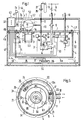
- Fig. 1 ein Schema einer erfindungsgemäss ausgebildeten Betankungseinrichtung;
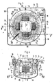
- Fig. 2 eine entsprechende Betankungseinrichtung in einem Längsschnitt entsprechend der Linie II-II in Fig. 3;
- Fig. 2a eine Einzelheit einer Betankungseinrichtung in einer abgewandelten Ausführungsform, in einer Teilansicht mit Teilschnitt entsprechend der Darstellung nach Fig. 2;
- Fig. 3 die Betankungseinrichtung in einem Horizontalschnitt entsprechend der Linie III-III in Fig. 2;
- Fig. 4 einen Vertikalschnitt entsprechend der Linie IV-IV in Fig. 3;
- Fig. 5 einen Horizontalschnitt entsprechend der Linie V-V in Fig. 4.
- 1 shows a diagram of a refueling device designed according to the invention;
- Figure 2 shows a corresponding refueling device in a longitudinal section along the line II-II in Fig. 3.
- 2a shows a detail of a refueling device in a modified embodiment, in a partial view with a partial section corresponding to the representation according to FIG. 2;
- Figure 3 shows the refueling device in a horizontal section along the line III-III in Fig. 2.
- Fig. 4 is a vertical section along the line IV-IV in Fig. 3;
- 5 shows a horizontal section along the line VV in FIG. 4.
Die Betankungseinrichtung nach Fig. 1 enthält einen kompressor 1 mit einer Antriebswelle 2, die mit einem elektrischen Motor 3 gekuppelt ist. Der Motor 3 ist in einem Druckbehälter 4 angeordnet, der einen Deckel 5 und einen an diesem über eine Dichtungsanordnung 29 befestigbaren Wandteil 6 mit einer Bodenpartie 6a aufweist. Der kompressor 1, der in beliebiger Bauart ausgeführt sein kann, ist mit einer Gehäusepartie 1a dichtend auf dem Deckel 5 angebracht und saugseitig an den Druckbehälter 4 angeschlossen, der über eine Saugleitung 7 an eine Quelle eines Gasbrennstoffs, beim dargestellten Beispiel eine Erdgasleitung 8, anschliessbar ist. Darstellungsgemäss kann der saugseitige Anschluss des Kompressors 1 durch ein Ansaugstück 7a gebildet sein, das mit einer im Deckel 5 vorgesehenen Durchtrittsöffnung 19a dichtend verbunden ist. Die Druckseite des Kompressors 1 ist einerseits über eine Entlastungsleitung 10 mit einem im Druckbehälter 4 angeordneten Umschaltorgan 21 verbunden, welches in einer Schaltstellung als Entlastungsventil wirkt, und andererseits über eine Speiseleitung 12 an einen zu betankenden Gasbrennstoffbehälter 13 anschliessbar, der beim dargestellten Beispiel als Treibstofftank eines nicht dargestellten Fahrzeuges ausgebildet sein kann.1 contains a
Die Saugleitung 7, die dargestellungsgemäss ein z.B. von Hand betätigbares Absperrorgan 14 und ein Filter 9 zum Abscheiden von im Erdgas gegebenenfalls enthaltenen Verunreinigungen enthalten kann, ist über ein Rückschlagventil 15 ebenfalls mit dem Umschaltorgan 21 verbunden, welches in einer anderen Schaltstellung als Einlassventil wirkt. Zur Ueberwachung des Eingangsdruckes des Gasbrennstoffs ist ein auf einen vorbestimmten Minimaldruck in der Saugleitung 7 fest einstellbarer Differenzdruckschalter 17 vorgesehen, dessen erster Eingang mit der Saugleitung 7, und dessen zweiter Eingang mit einer aus dem Druckbehälter 4 wegführenden Abströmleitung 18 verbunden ist, welche stromaufwärts des Differenzdruckschalters 17 mit einem auf einen vorbestimmten Oeffnungsdruck einstellbaren Sicherheitsventil 20 versehen ist. Die Abströmleitung 18 ist aus der unmittelbaren Umgebung der Betankungseinrichtung, z.B. über ein die Einrichtung überdeckendes Dach hinaus, weggeführt.The
Das Rückschlagventil 15 kann in das Umschaltorgan 21, darstellungsgemäss ein 3/2-Wegeventil, integriert sein, welches einen an die Saugleitung 7 anschliessbaren ersten Eingang, einen an die Entlastungsleitung 10 anschliessbaren zweiten Eingang und einen in den Innenraum des Druckbehälters 4 mündenden Ausgang A aufweist. Das Umschaltorgan 21 ist über ein Stellglied 22, z.B. einen Stellmotor oder, gemäss Fig. 1, einen Elektromagneten, zwischen einer Einlasstellung, in der die Saugleitung 7 mit dem Ausgang A verbunden und die Entlastungsleitung 10 abgesperrt ist, und einer in der Fig. 1 dargestellten Entlastungsstellung verstellbar, in der die Entlastungsleitung 10 mit dem Ausgang A verbunden und die Saugleitung 7 abgesperrt ist. Ein entsprechendes Umschaltorgan, welches nicht Gegenstand der vorliegenden Erfindung ist, ist z.B. aus der CH-PS 675 459 (P.6364) bekannt.The
Die Entlastungsleitung 10 ist innerhalb des Druckbehälters mit einem Hochdruckfühler 24 und einem auf einen vorbestimmten Maximaldruck des verdichteten Gasbrennstoffes einstellbaren Druckbegrenzungsventil 25 versehen, welches, wie in Fig. 1 angedeutet, einen in den Innenraum des Druckbehälters 4 mündenden, durch eine Berstscheibe 26 verschlossenen Ausgang A1 aufweisen kann. Die Speiseleitung 12 ist mit Absperrmitteln versehen, die darstellungsgemäss unter anderem ein z.B. von Hand betätigbares Absperrorgan 28 und/oder eine Kompressorseitig absperrende Kupplung enthalten können. Ein Rückschlagventil 27 verhindert das Zurückströmen des Gasbrennstoffs in die Speiseleitung 12.The
Der Differenzdruckschalter 17 und der Hochdruckfühler 24 sind über elektrische Signalleitungen 30 bzw. 31 an eine Steuereinrichtung 32 angeschlossen, welche über eine Steuerleitung 34 mit dem Stellglied 22 des Umschaltorgans 21, und über weitere elektrische Leitungen 33 und 35 mit dem Motor 3 bzw. einem Motor 37 eines beim dargestellten Beispiel ausserhalb des Druckbehälters 4 angeordneten Gebläses 36 verbunden ist. Der Kompressor 1, der Motor 3 und der Deckel 5 sind mit Temperaturfühlern T versehen, welche je über eine Signalleitung 38 bzw. 40 bzw. 41 mit der Steuereinrichtung 32 in Verbindung stehen. Die Steuereinrichtung 32 ist ferner über eine Signalleitung 42 an einen die Umgebungstemperatur erfassenden Temperaturfühler T1 angeschlossen und ist darstellungsgemäss in einer Schalteinheit 43 untergebracht, welche über eine Stromleitung 44 an eine nicht dargestellte Stromquelle anschliessbar ist.The
Die Schalteinheit 43 kann darstellungsgemäss ausserhalb des Druckbehälters 4, in einem zur Luftführung dienenden Gehäuse 46 angeordnet sein, welches einen den Wandteil 6 und die Bodenpartie 6a umgebenden Unterteil 47 und einen den Deckel 5 und den Kompressor 1 umgebenden Oberteil 48 aufweist. Der Unterteil 47 ist in seiner Bodenpartie mit einer Eintrittsöffnung 50 versehen, der das Gebläse 36 zugeordnet ist. Durch das Gebläse 36 wird Kühlluft in das Gehäuse 46 angesaugt, durch einen zwischen dem Wandteil 6 und der Seitenwand des Gehäuses 46 gebildeten Ringraum 51 gegen den Kompressor 1 geführt und durch eine im Oberteil 48 vorgesehene Austrittsöffnung 52 aus dem Gehäuse 46 abgeführt.As shown, the
Die Betankungseinrichtung wird über die z.B. durch einen Schlüssel betätigbare Schalteinheit 43 in Betrieb gesetzt, wobei in bekannter Weise, wie z.B. in der eingangs genannten EP-Patentanmeldung 0 300 222 beschrieben, über die Steuereinrichtung 32 das Umschaltorgan 21 aus der dargestellten Schaltstellung in die der Saugleitung 7 zugeordnete Durchflussstellung verstellt und der Motor 3 gestartet wird. Entsprechend wird das aus der Erdgasleitung 8 mit einem Druck von z.B. 20 mbar zugeführte Erdgas durch den Kompressor 1 auf einen vorbestimmten Fülldruck verdichtet und über die Speiseleitung 12 dem Gasbrennstoffbehälter 13 zugeführt, wobei der betriebsmässige Fülldruck über die Steuereinrichtung 32 in Abhängigkeit von Steuersignalen des Temperaturfühlers T1 und des Hochdruckfühlers 24 auf einen der jeweiligen Umgebungstemperatur entsprechenden Wert begrenzt wird. Durch das Druckbegrenzungsventil 25 ist ein Höchstwert des Fülldrucks einstellbar, der z.B. 230 bar betragen kann.The refueling device is operated via
Bei der dargestellten Ausführung wird der aus der Saugleitung 7 zugeführte Gasbrennstoff durch den Ausgang A des Umschaltorgans 21 in den die Armaturen und den Motor 3 enthaltenden Druckbehälter 4 geführt und aus diesem durch den Kompressor 1 angesaugt. Beim Erreichen des der Umgebungstemperatur entsprechenden Fülldrucks von z.B. 100 bar bis 200 bar wird über die Steuereinrichtung 32 das Umschaltorgan 21 in die dargestellte, der Entlastungsleitung 10 zugeordnete Durchflussstellung verstellt und der Motor 3 abgeschaltet. Entsprechend wird der im Kompressor 1 und in der Speiseleitung 12 verbliebene, verdichtete Gasbrennstoff durch den Ausgang A des Umschaltorgans 21 in den Druckbehälter 4 entspannt. In diesem Fall - oder wenn beim Ueberschreiten des am Druckbegrenzungsventil 25 eingestellten Höchstwerts des Fülldrucks die Berstscheibe 26 zerstört wird und der verdichtete Gasbrennstoff durch den Ausgang A1 in den Druckbehälter 4 austritt - wird in diesem ein durch das Sicherheitsventil 20 begrenzter Druck von z.B. 2 bis 3 bar aufgebaut. Beim Ueberschreiten dieses Drucks wird das Sicherheitsventil 20 geöffnet und eine entsprechende Menge des Gasbrennstoffs durch die mit einem relativ grossen Durchmesser ausführbare Abströmleitung 18, welche einen raschen Druckabbau gewährleistet, ins Freie abgeleitet.In the embodiment shown, the gas fuel supplied from the
Bei der beschriebenen Ausführung kann der Druckbehälter 4 für einen relativ geringen Innendruck ausgelegt werden, der nicht wesentlich höher ist als der am Sicherheitsventil 20 eingestellte Oeffnungsdruck. Entsprechend kann der Druckbehälter 4 in einer relativ leichten, einfachen Bauweise ausgeführt werden, die insbesondere relativ wenige, leicht abzudichtende Strömungsdurchgänge erfordert.In the embodiment described, the
Wie aus der eingangs genannten EP-Patentanmeldung 0 300 222 hervorgeht, können anstelle des Umschaltorgans 21 auch einzelne, je für sich betätigbare Armaturen - Einlasventil, Entlastungsventil, Rückschlagventil - vorgesehen sein. Ferner können nach einer nicht dargestellten Ausführungsform die Niederdruckarmaturen - z.B. das Rückschlagventil 15, ein Einlassventil und der Differenzdruckschalter - ausserhalb des Druckbehälters 4 angeordnet sein, der dann nur die den höchsten Drücken ausgesetzten Armaturen - ein Entlastungsventil und das Druckbegrenzungsventil 25 - sowie das Sicherheitsventil 20 enthält.As can be seen from the above-mentioned EP patent application 0 300 222, instead of the switching
Der Kompressor kann als zwei- oder mehrstufiger, entsprechend der gegenständlichen Darstellung der Betankungseinrichtung nach den Fig. 2 bis 5 als vierstufiger kolbenkompressor ausgeführt sein, der zwei auf einer gemeinsamen horizontalen Achse 53 eineinander gegenüberliegend angeordnete Zylinder 55 und 57 sowie zwei gegenüber diesen um 90° versetzt auf einer gemeinsamen horizontalen Achse 54 eineinander gegenüberliegend angeordnete Zylinder 56 und 58 aufweist, in denen nicht dargestellte Kolben geführt sind. Jedes der auf der gleichen Achse 53 bzw. 54 angeordneten kolbenpaare kann in bekannter Weise über eine ihre kolbenstangen verbindende Antriebsanordnung mit der einen zentralen Kurbelraum 60 durchsetzenden, als Kurbelwelle ausgebildeten vertikalen Antriebswelle 2 gekuppelt sein, wobei in den Zylindern 55 und 56 die erste bzw. die zweite Verdichtungsstufe, und in den Zylindern 57 und 58 die dritte bzw. die vierte Verdichtungsstufe ausgebildet sein können. Ein entsprechender Kompressor, dessen Ausführung nicht Gegenstand der vorliegenden Erfindung ist, ist z.B. aus der EP-Patentanmeldung 0 389 414 (P.6254) bekannt. Das mit einem Druck von z.B. 20 mbar in den Kurbelraum 60 eingeführte Erdgas kann, z.B. durch eine im Kolben vorgesehene Ansaugöffnung, in den Zylinder 55 angesaugt, auf einen Druck von z.B. 5 bar verdichtet und nacheinander im Zylinder 56 auf einen Druck von z.B. 20 bar, im Zylinder 57 auf einen Druck von z.B. 60 bar und im Zylinder 58 auf einen Enddruck von z.B. 200 bar verdichtet und über die Speiseleitung 12 dem Gasbrennstoffbehälter 13 zugeführt werden.The compressor can be designed as a two-stage or multi-stage, corresponding to the representation of the refueling device according to FIGS. 2 to 5 as a four-stage piston compressor, the two
Wie insbesondere aus der Fig. 4 hervorgeht, ist der kompressor 1 mit einer auf den Deckel 5 des Druckbehälters 4 aufsetzbaren, gegen dessen Innenraum offenen Gehäusepartie 1a ausgeführt, welche einen in die Durchtrittsöffnung 19 des Deckels 5 einführbaren zylindrischen Absatz 61 aufweist. Der Deckel 5 des bei der dargestellten Ausführung zylindrischen Druckbehälters 4 ist mit einer die Durchtrittsöffnung 19 umgebenden, zentralen Kragenpartie 62 ausgeführt, durch welche die Gehäusepartie 1a gestützt und der Absatz 61 über eine Dichtungsanordnung 59 dichtend geführt ist. In einer am Deckel 5 befestigten Halterung 63 ist der Motor 3 mit vertikaler Drehachse angeordnet. Der Motor 3 enthält einen an der Halterung 63 befestigbaren Statorteil 64 und einen Rotor 65, welcher mit der Antriebswelle 2 des Kompressor 1 über eine lösbare Kupplung verbunden sein kann oder welcher, wie in Fig. 4 angedeutet, mit der Antriebswelle 2 zu einer durch die Durchtrittsöffnung 19 in den Statorteil 63 einführbaren Einbaueinheit verbunden ist. Gemäss Fig. 4 kann der Rotor 65 mit dem Kompressor 1 zusammengebaut und durch Aufsetzen und Einführen der Gehäusepartie 1a auf bzw. in die Kragenpartie 62 auf einfache Weise eingebaut und durch Abheben des Kompressors 1 entsprechend leicht ausgebaut werden.As can be seen in particular from FIG. 4, the
In dem zwischen der Halterung 63 und dem Wandteil 6 des Druckbehälters 4 gebildeten Ringraum sind der Differenzdruckschalter 17, das Sicherheitsventil 20, das Umschaltorgan 21, der Hochdruckfühler 24 und das Druckbegrenzungsventil 25 angeordnet. Im Deckel 5 sind Anschlüsse 67 und 68 für die Saugleitung 7 bzw. die Abströmleitung 18 sowie Anschlüsse 70 und 71 für die Entlastungsleitung 10 bzw. die elektrischen Leitungen 30, 31, 33, 34 und 35 vorgesehen. Der Anschluss 67 mündet in eine im Deckel 5 ausgebildete Bohrung 72, welche zur Aufnahme des Filters 9 dient und welche über einen Anschluss 67a mit dem Rückschlagventil 15 des Umschaltorgans 21 in Verbindung steht. Ueber einen entsprechenden Anschluss 68a steht der Anschluss 68 in nicht weiter dargestellter Weise mit dem Differenzdruckschalter 17 und dem Sicherheitsventil 20 in Verbindung. Der Differenzdruckschalter 17 und das Sicherheitsventil 20 können darstellungsgemäss mit dem am Deckel 5 befestigbaren Umschaltorgan 21 zu einer Einbaueinheit verbunden sein. Die am Zylinder 58 angeschlossene Entlastungsleitung 10 ist über den Anschluss 70 mit dem Druckbegrenzungsventil 25 verbunden, welches mit dem Hochdruckfühler 24 zu einer am Deckel 5 befestigbaren Einbaueinheit zusammengefasst und über einen Leitungsabschnitt 10a mit dem Eingang des Umschaltorgans 21 verbunden ist.The
Nach einer anderen, in der Fig. 2a teilweise dargestellten Ausführungsform kann das Druckbegrenzungsventil 25 auch ausserhalb des Druckbehälters 4, innerhalb des mit diesem dichtend verbundenen Kompressorgehäuses, angeordnet und an einen Kanal 10b angeschlossen sein, der die Druckseite des Kompressors 1 mit dessen Saugseite verbindet. Bei dieser Ausführung, die mit Ausnahme der Anordnung des Druckbegrenzungsventils 25 der Ausführung nach den Fig. 2 bis 5 entspricht, ist der Kanal 10b mit dem Druckraum des Zylinders 58 verbunden und durch das Druckbegrenzungsventil 25 abgeschlossen, dessen Ausgang A1 in den gegen den Druckbehälter 4 hin offenen Kurbelraum 60 mündet. Beim Ueberschreiten des am Druckbegrenzungsventil 25 eingestellten Drucks wird der durch den Ausgang A1 austretende verdichtete Gasbrennstoff entsprechend entspannt und erneut durch den Kompressor 1 angesaugt bzw. - beim Ansprechen des in der Fig. 2a nicht dargestellten Sicherheitsventils 20 - über die Abströmleitung 18 abgeführt. Der Druckraum des Zylinders 58 ist ferner in beschriebener Weise über die Entlastungsleitung 10 mit den im Druckbehälter 4 angeordneten, in der Fig. 2a nicht dargestellten Steuer- und Ueberwachungselementen - Hochdruckfühler 24 und Umschaltorgan 21 - sowie über die Speiseleitung 12 mit dem Gasbrennstoffbehälter 13 verbindbar. Durch diese Ausführung kann eine weitere Vereinfachung des Aufbaues der Betankungseinrichtung, insbesondere hinsichtlich der im Druckbehälter 4 vorzusehenden Anschlüsse, erzielt werden.According to another embodiment, partially shown in FIG. 2a, the
Entsprechend der Darstellung nach den Fig. 2 und 3 ist der Deckel 5 des Druckbehälters 4 über drei an seinem Umfang verteilt angeordnete Konsolen 74 und Gummilager 75 auf Stützpartien 76 des zur Luftführung dienenden Gehäuses 46 abgestützt. Die Stützpartien 76 sind am Unterteil 47 ausgebildet, welcher den Wandteil 6 und den Deckel 5 in einem relativ geringen radialen Abstand umschliesst und welcher mit einer oberhalb des Deckels 5 angeordneten, den Ringraum 51 und die Randpartie des Deckels 5 überdeckenden Prallplatte 77 verbunden ist. Durch die Prallplatte 77 kann die den Ringraum 51 von unten nach oben durchströmende Kühlluft entlang dem Deckel 5 gegen den Kompressor 1 hin umgelenkt und entlang den Zylindern 55, 56, 57 und 58 nach oben abgeführt werden. Entsprechend kann eine für die Kühlung des Druckbehälters 4 und des Kompressors 1 günstige Führung der Luftströmung erreicht werden.According to the representation according to FIGS. 2 and 3, the
Der Deckel 5 ist mit Kühlrippen 78 ausgeführt, welche - in der Draufsicht nach Fig. 3 gesehen - vom äusseren Umfang aus spiralartig gekrümmt gegen den Uhrzeigensinn zur kragenpartie 62 hin verlaufen, wobei sie im Deckel 5 von der Prallwand 77 überdeckte und im Bereich der Zylinder 55, 57, 57, 58 nach oben offene Luftführkanäle 80 begrenzen. Entsprechend gelangt die durch das Gebläse 36 in den Ringraum 51 geförderte kühlluft, welche entsprechend den Pfeilen L1 schraubenlinienartig um den Wandteil 6 herum gegen die Prallwand 77 geführt wird, im Umfangsbereich des Deckels 5 in die Kanäle 80 und wird durch diese gegen die Gehäusepartie 1a sowie quer zu den Zylindern 55, 56, 57 und 58, zumindest annähernd in Richtung der Längsachse B des Druckgefässes 4, nach oben abgeführt. Die Zylinder 55, 56, 57 und 58 können mit ringförmigen Kühlrippen 81 und mit über ihre Stirnflächen vertikal verlaufenden kühlrippen 82 versehen sein, welche in vertikaler Richtung durchströmbare Strömungswege begrenzen und damit eine gute Kühlwirkung gewährleisten. Wie insbesondere aus der Fig. 3 hervorgeht, können die kühlrippen 78 des Deckels 5 evolventenförmig gekrümmt verlaufen, wobei die kanäle 80 je eine über ihre Länge im wesentlichen konstante Breite aufweisen können, so dass eine strömungsgünstige Führung der Kühlluft und damit eine wirksame kühlung des Deckels 5 und des Kompressors 1 erzielbar ist. Es ist jedoch auch eine Ausführung möglich, bei der eine ausreichende Kühlung durch einfacher herzustellende, gerade verlaufende, z.B. sternförmig angeordnete kühlrippen erzielbar ist.The
Das Gebläse 36 ist über eine Halterung, die drei mit dem Motor 37 verbundene Tragarme 83 enthalten kann, im Unterteil 47 des Gehäuses 46 abgestützt. In einem im Oberteil 48 des Gehäuses 46 vorgesehenen, für Inspektion, Wartung und Bedienung gut zugänglichen Einbaubereich kann die Schalteinheit 43 in Form einer Schalttafel untergebracht sein, welche mit Druckschaltern 84 zur Betätigung der Betankungseinrichtung versehen sein kann. Entsprechend der Darstellung nach den Fig. 2 und 3 kann das den Druckbehälter 4 und den Kompressor 1 umgebende Gehäuse 46 in einem weiteren, äusseren Gehäuse 85 angeordnet sein, welches gemäss Fig. 3 mit quadratischem Querschnitt ausgeführt sein kann. Das innere Gehäuse 46 kann über mehrere, z.B. drei konsolen 86, auf entsprechende Stützpartien 87 des Gehäuses 85 aufgesetzt sein. Das äussere Gehäuse 85 kann mit dem inneren Gehäuse 46 durch Trennwände 88 verbunden sein, welche den zwischen den Gehäusen 85 und 46 gebildeten Raum in zwei nacheinander durchströmbare Teilräume 89 und 90 unterteilen, welche nur über die untere Eintrittsöffnung 50 und die in der Prallwand 77 ausgebildete Oeffnung miteinander in Verbindung stehen. Dabei kann der Teilraum 89 mit einer am oberen Ende des Gehäuses 85 angeordneten Eintrittsöffnung 91, und der Teilraum 90 mit einer am unteren Ende des Gehäuses 85 angeordneten Austrittsöffnung 92 in Verbindung stehen. Das äussere Gehäuse 85 kann ferner mit einem verschliessbaren Deckel 93 versehen sein, durch den die Druckschalter 84 überdeckt und vor unbefugter Betätigung geschützt werden können.The
Während des Betriebes wird durch das Gebläse 36 die kühlluft entsprechend den Pfeilen L durch die Eintrittsöffnung 91 und den Teilraum 89 angesaugt, entsprechend den Pfeilen L1 entlang dem Druckbehälter 4 in den Oberteil 48 des inneren Gehäuses 46 geführt und entsprechend den Pfeilen L2 durch den Teilraum 90 und die Austrittsöffnung 92 aus dem Gehäuse 85 hinausgeführt. Ensprechend wird auf engstem Raum eine Kühlluftführung erreicht, welche auch bei der durch die erfindungsgemässe Ausführung erzielbaren kompakten Bauweise der Betankungsanlage eine intensive kühlung sowohl des Druckbehälters 4 als auch des Kompressors 1 ermöglicht. Durch die Gehäuse 46 und 85 kann zugleich ein wirksamer Lärmschutz erzielt werden.During operation, the cooling air is sucked in by the
Es sind zahlreiche abgewandelte Ausführungsformen der Erfindung möglich. So kann z.B. der komplette Motor des Kompressors an der Innenseite des als Tragteil ausgebildeten Deckels 5 befestigt und über eine im Bereich der Durchtrittsöffnung 19 angeordnete, bekannte Kupplungsanordnung mit der Antriebswelle des Kompressors verbunden sein. Nach einer anderen Ausführungsform können der kompressor und der Motor innerhalb des Druckbehälters angeordnet sein, wodurch eine weitere Reduktion von Dichtstellen gegen die Umgebung erzielbar ist. Nach einer weiteren Ausführungsform kann der Kompressor innerhalb und der Motor ausserhalb des Druckbehälters angeordnet sein. Ferner kann nach einer Ausführungsform der Motor des kompressors ausserhalb des Druckbehälters, z.B. innerhalb der an der Aussenseite des Deckels 5 oder eines entsprechenden Tragteils befestigten Gehäusepartie des Kompressors angebracht sein, wobei der lediglich für die Aufnahme der Armaturen - gegebenenfalls nur für die den höchsten Drücken ausgesetzten Armaturen - auszulegende Druckbehälter entsprechend klein ausgeführt werden kann. Abweichend von den dargestellten Ausführungen, kann auch ein anderer Teil, z.B. eine Bodenpartie, des Druckbehälters als Tragteil für den Kompressor und/oder den Motor ausgebildet sein. Es ist auch eine Ausführung möglich, bei der etwa im Gehäuse 46, insbesondere an der Prallwand 77, den kühlrippen 78 entsprechende, leitschaufelartige Führungselemente für die kühlluft vorgesehen sind.Numerous modified embodiments of the invention are possible. For example, the complete motor of the compressor can be attached to the inside of the
Claims (11)
Applications Claiming Priority (2)
| Application Number | Priority Date | Filing Date | Title |
|---|---|---|---|
| CH159391 | 1991-05-30 | ||
| CH1593/91 | 1991-05-30 |
Publications (2)
| Publication Number | Publication Date |
|---|---|
| EP0516580A1 true EP0516580A1 (en) | 1992-12-02 |
| EP0516580B1 EP0516580B1 (en) | 1995-03-22 |
Family
ID=4214045
Family Applications (1)
| Application Number | Title | Priority Date | Filing Date |
|---|---|---|---|
| EP92810282A Expired - Lifetime EP0516580B1 (en) | 1991-05-30 | 1992-04-16 | Filling device for a gaseous fuel tank |
Country Status (6)
| Country | Link |
|---|---|
| US (1) | US5263826A (en) |
| EP (1) | EP0516580B1 (en) |
| AU (1) | AU647624B2 (en) |
| CA (1) | CA2068164C (en) |
| DE (1) | DE59201707D1 (en) |
| NZ (1) | NZ242143A (en) |
Cited By (5)
| Publication number | Priority date | Publication date | Assignee | Title |
|---|---|---|---|---|
| EP2093475A1 (en) | 2008-02-20 | 2009-08-26 | Air Products and Chemicals, Inc. | Compressor fill method and apparatus |
| EP1447614A3 (en) * | 2003-02-12 | 2011-04-06 | G.I. & E. S.p.A. | Station for supplying pressurized gas to tanks, in particular tanks installed on vehicles |
| CN102563343A (en) * | 2010-11-29 | 2012-07-11 | 通用汽车环球科技运作有限责任公司 | Compressed gas tank system with fast fueling ability at any vessel pressure |
| EP3792340A1 (en) * | 2019-09-04 | 2021-03-17 | XL Beteiligungen GmbH & Co. KG | Gas-tight container |
| RU218776U1 (en) * | 2023-03-21 | 2023-06-09 | Публичное акционерное общество "КАМАЗ" | Device for monitoring and charging a hydropneumatic accumulator with gas |
Families Citing this family (17)
| Publication number | Priority date | Publication date | Assignee | Title |
|---|---|---|---|---|
| US5370159A (en) * | 1993-07-19 | 1994-12-06 | Price Compressor Company, Inc. | Apparatus and process for fast filling with natural gas |
| US5501200A (en) * | 1994-06-28 | 1996-03-26 | Bogartz; Stuart P. | Compressed gas fueling system |
| US5957667A (en) * | 1997-05-23 | 1999-09-28 | Ballard Generation Systems Inc. | Oilless compressor with a pressurizable crankcase and motor containment vessel |
| RU2336434C2 (en) * | 2002-10-04 | 2008-10-20 | Фюелмэйкер Корпорейшн | Gas compression system |
| CA2440255A1 (en) * | 2003-09-09 | 2005-03-09 | Fuelmaker Corporation | Gas compressor with drier and radio emission controls |
| US7011118B2 (en) * | 2002-10-04 | 2006-03-14 | 2045951 Ontario Inc. | Residential compressor for refueling motor vehicles that operate on gaseous fuels |
| US6899146B2 (en) | 2003-05-09 | 2005-05-31 | Battelle Energy Alliance, Llc | Method and apparatus for dispensing compressed natural gas and liquified natural gas to natural gas powered vehicles |
| US9618158B2 (en) | 2011-05-02 | 2017-04-11 | New Gas Industries, L.L.C. | Method and apparatus for compressing gas in a plurality of stages to a storage tank array having a plurality of storage tanks |
| SE536423C2 (en) | 2011-08-16 | 2013-10-22 | Birgit Evermark | Method and system for producing an image by tile on a wall, floor or ceiling |
| US10851944B2 (en) | 2012-01-31 | 2020-12-01 | J-W Power Company | CNG fueling system |
| US9765930B2 (en) * | 2012-01-31 | 2017-09-19 | J-W Power Company | CNG fueling system |
| US10018304B2 (en) | 2012-01-31 | 2018-07-10 | J-W Power Company | CNG fueling system |
| US20140182561A1 (en) * | 2013-09-25 | 2014-07-03 | Eghosa Gregory Ibizugbe, JR. | Onboard CNG/CFG Vehicle Refueling and Storage Systems and Methods |
| CN103615657A (en) * | 2013-11-05 | 2014-03-05 | 江苏现代造船技术有限公司 | Natural gas transmission system of LNG power driving vessel |
| CN106030186B (en) | 2014-02-21 | 2019-04-30 | 株式会社神户制钢所 | Gas supply system and hydrogenation stations |
| US10088109B2 (en) | 2014-11-03 | 2018-10-02 | Gilbarco Inc. | Compressed gas filling method and system |
| US10551001B2 (en) | 2015-09-03 | 2020-02-04 | J-W Power Company | Flow control system |
Citations (2)
| Publication number | Priority date | Publication date | Assignee | Title |
|---|---|---|---|---|
| EP0356377A1 (en) * | 1988-08-15 | 1990-02-28 | GebràDer Sulzer Aktiengesellschaft | Gas-filling device for motor vehicles |
| CH676951A5 (en) * | 1988-08-12 | 1991-03-28 | Sulzer Ag | Vehicle gas tank filling appliance - has second internal housing for compressor-motor group |
Family Cites Families (4)
| Publication number | Priority date | Publication date | Assignee | Title |
|---|---|---|---|---|
| US2136959A (en) * | 1934-10-26 | 1938-11-15 | Edward A Winfield | Fuel supply system |
| US4700680A (en) * | 1984-05-08 | 1987-10-20 | Teledyne Industries, Inc. | Two stage fuel pump |
| US4799686A (en) * | 1986-12-19 | 1989-01-24 | Martinez Eduardo S | Board game apparatus for a banking game |
| EP0300222B1 (en) * | 1987-07-23 | 1992-08-12 | GebràDer Sulzer Aktiengesellschaft | Filling device for a gaseous-fuel reservoir |
-
1992
- 1992-03-26 NZ NZ242143A patent/NZ242143A/en not_active IP Right Cessation
- 1992-03-27 US US07/858,736 patent/US5263826A/en not_active Expired - Lifetime
- 1992-04-16 DE DE59201707T patent/DE59201707D1/en not_active Expired - Lifetime
- 1992-04-16 EP EP92810282A patent/EP0516580B1/en not_active Expired - Lifetime
- 1992-05-07 CA CA002068164A patent/CA2068164C/en not_active Expired - Lifetime
- 1992-05-29 AU AU17289/92A patent/AU647624B2/en not_active Expired
Patent Citations (2)
| Publication number | Priority date | Publication date | Assignee | Title |
|---|---|---|---|---|
| CH676951A5 (en) * | 1988-08-12 | 1991-03-28 | Sulzer Ag | Vehicle gas tank filling appliance - has second internal housing for compressor-motor group |
| EP0356377A1 (en) * | 1988-08-15 | 1990-02-28 | GebràDer Sulzer Aktiengesellschaft | Gas-filling device for motor vehicles |
Cited By (7)
| Publication number | Priority date | Publication date | Assignee | Title |
|---|---|---|---|---|
| EP1447614A3 (en) * | 2003-02-12 | 2011-04-06 | G.I. & E. S.p.A. | Station for supplying pressurized gas to tanks, in particular tanks installed on vehicles |
| EP2093475A1 (en) | 2008-02-20 | 2009-08-26 | Air Products and Chemicals, Inc. | Compressor fill method and apparatus |
| US8365777B2 (en) | 2008-02-20 | 2013-02-05 | Air Products And Chemicals, Inc. | Compressor fill method and apparatus |
| CN102563343A (en) * | 2010-11-29 | 2012-07-11 | 通用汽车环球科技运作有限责任公司 | Compressed gas tank system with fast fueling ability at any vessel pressure |
| CN102563343B (en) * | 2010-11-29 | 2015-10-14 | 通用汽车环球科技运作有限责任公司 | The compressed gas tank system of quick fueling ability is all had under any container pressure |
| EP3792340A1 (en) * | 2019-09-04 | 2021-03-17 | XL Beteiligungen GmbH & Co. KG | Gas-tight container |
| RU218776U1 (en) * | 2023-03-21 | 2023-06-09 | Публичное акционерное общество "КАМАЗ" | Device for monitoring and charging a hydropneumatic accumulator with gas |
Also Published As
| Publication number | Publication date |
|---|---|
| CA2068164A1 (en) | 1992-12-01 |
| US5263826A (en) | 1993-11-23 |
| DE59201707D1 (en) | 1995-04-27 |
| NZ242143A (en) | 1994-03-25 |
| AU1728992A (en) | 1992-12-03 |
| AU647624B2 (en) | 1994-03-24 |
| EP0516580B1 (en) | 1995-03-22 |
| CA2068164C (en) | 2003-04-08 |
Similar Documents
| Publication | Publication Date | Title |
|---|---|---|
| EP0516580B1 (en) | Filling device for a gaseous fuel tank | |
| EP0300222B1 (en) | Filling device for a gaseous-fuel reservoir | |
| EP0920587B1 (en) | Refrigerant compressor | |
| DE102017122327B4 (en) | scroll compressor | |
| DE2824401A1 (en) | TURBOCHARGER CONTROL | |
| DE102006024816A1 (en) | Device for venting a crankcase | |
| WO1998048165A1 (en) | Fuel injection system for an internal combustion engine with a common rail | |
| EP3477167B1 (en) | Thermal management module | |
| WO2016184839A1 (en) | Oil-lubricated slide vane rotary vacuum pump with oil separating and reconditioning device | |
| WO1999061799A1 (en) | Frictional vacuum pump with chassis, rotor, housing and device fitted with such a frictional vacuum pump | |
| DE102010055316B4 (en) | Device for venting and ventilating a fuel tank | |
| DE10308420A1 (en) | Test gas leak detector | |
| EP0123843A1 (en) | Air drier | |
| EP1240433B1 (en) | Dry compressing vacuum pump having a gas ballast device | |
| DE3344765A1 (en) | Submerged pump | |
| DE19717799C2 (en) | Unit for a compact heating system | |
| DE2400325A1 (en) | GENTLE COMPRESSOR WORKING WITH OIL INJECTION | |
| DE3841097A1 (en) | SUCTION DEVICE FOR THE COMBUSTION AIR OF A MOTOR VEHICLE FRONT ENGINE | |
| DE102016225923A1 (en) | Pump unit for a hydraulic system and duct element for a pump set | |
| DE102016011394A1 (en) | Screw compressor for a commercial vehicle | |
| DE3517493A1 (en) | SCREW COMPRESSOR SYSTEM IN A COMPACT HOUSING | |
| WO1997049916A1 (en) | Fuel supply pump for a fuel injection pump for internal combustion engines | |
| EP0201672A2 (en) | Compact screw-type compressor | |
| EP0249657B1 (en) | Apparatus with a vane pump | |
| EP1217310B1 (en) | Compact unit |
Legal Events
| Date | Code | Title | Description |
|---|---|---|---|
| PUAI | Public reference made under article 153(3) epc to a published international application that has entered the european phase |
Free format text: ORIGINAL CODE: 0009012 |
|
| AK | Designated contracting states |
Kind code of ref document: A1 Designated state(s): CH DE FR GB IT LI NL |
|
| 17P | Request for examination filed |
Effective date: 19930423 |
|
| 17Q | First examination report despatched |
Effective date: 19940412 |
|
| RAP1 | Party data changed (applicant data changed or rights of an application transferred) |
Owner name: MASCHINENFABRIK SULZER-BURCKHARDT AG |
|
| GRAA | (expected) grant |
Free format text: ORIGINAL CODE: 0009210 |
|
| AK | Designated contracting states |
Kind code of ref document: B1 Designated state(s): CH DE FR GB IT LI NL |
|
| ET | Fr: translation filed | ||
| GBT | Gb: translation of ep patent filed (gb section 77(6)(a)/1977) |
Effective date: 19950327 |
|
| REF | Corresponds to: |
Ref document number: 59201707 Country of ref document: DE Date of ref document: 19950427 |
|
| ITF | It: translation for a ep patent filed |
Owner name: ING. ZINI MARANESI & C. S.R.L. |
|
| PLBE | No opposition filed within time limit |
Free format text: ORIGINAL CODE: 0009261 |
|
| STAA | Information on the status of an ep patent application or granted ep patent |
Free format text: STATUS: NO OPPOSITION FILED WITHIN TIME LIMIT |
|
| 26N | No opposition filed | ||
| REG | Reference to a national code |
Ref country code: CH Ref legal event code: PUE Owner name: MASCHINENFABRIK SULZER-BURCKHARDT AG TRANSFER- GRE |
|
| REG | Reference to a national code |
Ref country code: GB Ref legal event code: 732E |
|
| NLS | Nl: assignments of ep-patents |
Owner name: GREENFIELD AG |
|
| REG | Reference to a national code |
Ref country code: FR Ref legal event code: TP |
|
| REG | Reference to a national code |
Ref country code: GB Ref legal event code: IF02 |
|
| PGFP | Annual fee paid to national office [announced via postgrant information from national office to epo] |
Ref country code: DE Payment date: 20110421 Year of fee payment: 20 Ref country code: CH Payment date: 20110428 Year of fee payment: 20 Ref country code: FR Payment date: 20110510 Year of fee payment: 20 |
|
| PGFP | Annual fee paid to national office [announced via postgrant information from national office to epo] |
Ref country code: NL Payment date: 20110426 Year of fee payment: 20 Ref country code: GB Payment date: 20110421 Year of fee payment: 20 |
|
| PGFP | Annual fee paid to national office [announced via postgrant information from national office to epo] |
Ref country code: IT Payment date: 20110422 Year of fee payment: 20 |
|
| REG | Reference to a national code |
Ref country code: DE Ref legal event code: R071 Ref document number: 59201707 Country of ref document: DE |
|
| REG | Reference to a national code |
Ref country code: DE Ref legal event code: R071 Ref document number: 59201707 Country of ref document: DE |
|
| REG | Reference to a national code |
Ref country code: NL Ref legal event code: V4 Effective date: 20120416 |
|
| REG | Reference to a national code |
Ref country code: CH Ref legal event code: PL |
|
| REG | Reference to a national code |
Ref country code: GB Ref legal event code: PE20 Expiry date: 20120415 |
|
| PG25 | Lapsed in a contracting state [announced via postgrant information from national office to epo] |
Ref country code: DE Free format text: LAPSE BECAUSE OF EXPIRATION OF PROTECTION Effective date: 20120417 |
|
| PG25 | Lapsed in a contracting state [announced via postgrant information from national office to epo] |
Ref country code: GB Free format text: LAPSE BECAUSE OF EXPIRATION OF PROTECTION Effective date: 20120415 |