EP0515469B1 - Procede et appareil de commande d'un moteur a induction a courant alternatif par mesurage indirect de la tension de l'entrefer - Google Patents
Procede et appareil de commande d'un moteur a induction a courant alternatif par mesurage indirect de la tension de l'entrefer Download PDFInfo
- Publication number
- EP0515469B1 EP0515469B1 EP91904122A EP91904122A EP0515469B1 EP 0515469 B1 EP0515469 B1 EP 0515469B1 EP 91904122 A EP91904122 A EP 91904122A EP 91904122 A EP91904122 A EP 91904122A EP 0515469 B1 EP0515469 B1 EP 0515469B1
- Authority
- EP
- European Patent Office
- Prior art keywords
- stator
- voltage
- stator winding
- control signal
- current
- Prior art date
- Legal status (The legal status is an assumption and is not a legal conclusion. Google has not performed a legal analysis and makes no representation as to the accuracy of the status listed.)
- Expired - Lifetime
Links
Images

Classifications
-
- H—ELECTRICITY
- H02—GENERATION; CONVERSION OR DISTRIBUTION OF ELECTRIC POWER
- H02P—CONTROL OR REGULATION OF ELECTRIC MOTORS, ELECTRIC GENERATORS OR DYNAMO-ELECTRIC CONVERTERS; CONTROLLING TRANSFORMERS, REACTORS OR CHOKE COILS
- H02P21/00—Arrangements or methods for the control of electric machines by vector control, e.g. by control of field orientation
- H02P21/06—Rotor flux based control involving the use of rotor position or rotor speed sensors
- H02P21/10—Direct field-oriented control; Rotor flux feed-back control
Definitions
- This invention relates to an improved method and apparatus for controlling an AC induction motor by indirect measurement of the air-gap voltage of the AC induction motor and using said air-gap voltage for generating an optimal modulation frequency for the conversion of control signals from field coordinates to drive signals in stator coordinates for the AC induction motor.
- the modulation frequency is generated so that the magnetizing current is constant, which is a necessary condition for obtaining Natural Field Orientation.
- Swedish patent No. 8000118 discloses a control system which creates field orientation without field measurement, and is presently called "Natural Field Orientation”.
- the motor contributes to the field orientation in a natural way, thanks to the inherent properties of all AC induction motors.
- Said system operates with voltage control, and requires a speed sensor on the motor shaft.
- the present invention is a development and an improvement of said system and eliminates the speed sensor.
- the present invention can be used with voltage as well as with current control.
- the motor is controlled by a control vector in field coordinates.
- the externally generated control vector is converted from field coordinates to stator coordinates by a first vector rotator and connected to the motor via frequency inverters. An airgap voltage appears in the motor.
- the present invention is characterized by the features of Claims 1 and 7.
- the airgap voltage has a central role in the AC induction motor.
- the present invention is based on indirect measurement of the airgap voltage. Then, the measured airgap voltage vector is transformed to field coordinates by a second vector rotator. An optimal rotation frequency is generated, proportional to the amplitude of the measured airgap voltage and both the vector rotators are controlled or rotated with this frequency, resulting in a constant ratio between the amplitude of the air-gap voltage and the modulation frequency, thereby obtaining a constant amplitude of the magnetizing field current during all operating conditions. Quadrature between the field current and the rotor current in each phase is automatically obtained, thanks to the constant amplitude of the magnetizing field current.
- the resistive rotor current is frequency independent and can be controlled without disturbing the field current or being disturbed by the field current. This can be defined as decoupled control of the two currents.
- decoupled control of the two currents are naturally obtained, thanks to the optimal modulation frequency.
- a control system for an AC induction motor comprising a stator, a rotor, at least two stator windings and rotor windings, said control system comprising control signals, a first vector rotator for rotating said control signals with a first angle ( ⁇ ) for providing output signals connected to frequency inverters for providing drive signals to each stator winding of the motor, said first angle ( ⁇ ) being the time integral of a rotation frequency (w) which is controlled essentially for maintaining the amplitude of the magnetizing currents of each stator winding constant.
- control system comprises a means for measuring the voltages and/or currents of said drive signals, at least a second vector rotator for counterrotating said measured voltages and/or currents with a second angle (- ⁇ ) which is the inverse of said first angle ( ⁇ ); a means for controlling said rotation frequency (w) in dependence of said counterrotated measured voltages and/or currents essentially for maintaining the amplitude of said magnetizing currents of each stator winding constant.
- the present invention is based on an extremely simple motor model, it permits mathematically exact control.
- the leakage inductances can be neglected or included in the motor model.
- the new control system is inherently insensitive for variations in the rotor resistance. Compensation for variations in the stator resistance can be made.
- the present invention is based on estimated values of the airgap voltage in the motor.
- Field oriented control is a geometric control principle.
- the field orientation is related to the geometric field angle.
- complex vectors are used to describe voltage, current and field vectors in a geometrical plane. These geometrical vectors must not be confused with the complex electrical vectors used to describe sinusoidal alternating quantities in classical AC circuit theory.
- Phenomena in the AC induction motor can be described by help of both vector types, but not by both types simultaneously. A choice must be made.
- the description of the present invention concentrates on phenomena in one single motor phase. Thus, the classical AC circuit theory will be used in the first part of the description, with complex electrical vectors.
- a complex electrical vector is described by one single voltage or current.
- each terminal on the vector rotator controls a complete electrical vector.
- the vector rotator has two input vectors and two output vectors, one for each motor phase.
- a complex geometrical vector is described by two different voltages or currents. (Compare for example with Lissajoux figures on an oscilloscope, created by two voltages.) Thus, two terminals on the vector rotator are required for the description of one geometrical vector.
- the present invention relates to qualified control systems for high performance applications, for example servo applications.
- Field Oriented Control was created by Blaschke at the end of the 1960's. This method is based on direct measurement of the magnetic field by Hall members in the air-gap of the motor. From the measured signals, the angular position of the magnetic field is determined, and thence the control signals can be transformed so that they are correctly aligned in view of the actual position of the magnetic field of the motor. This method is named “Direct Field Orientation”. For a more detailed explanation, please refer to the article: "The principle of field orientation as applied to the new Transvector closed-loop control system for rotating-field machines", by Felix Blaschke, Siemens Review, Vol. 34, pp 217 - 220 May 1972.
- Hall members mainly since they generate weak signals and since it is desired to use standard motors without measuring members.
- a possible method is to estimate the voltage over the main inductance of the motor and integrate said voltage, which gives a value of the magnetic field.
- the main drawback with said method is that integration at zero (or low) frequency gives undetermined results, since offset voltages of the integrator will result in drift of the integrator to the positive or negative rail.
- WO-A-8201628 there is described a variant of the method of the preceeding paragraph which solves the problem of integrator drift.
- the stator current is used as a measure of the magnetic field.
- the terminal voltage is integrated.
- the present invention is a new approach and solves the problems of "Field Oriented Control” in a new way, and we call it “Natural Field Orientation” in order to distinguish it from “Direct” and “Indirect” field orientation.
- Natural Field Orientation can be defined as a method to obtain correct field orientation by help of constant amplitude of the magnetizing currents in each phase which results in quadrature between the magnetizing current and the rotor current.
- the constant amplitude is obtained by making the frequency proportional to the airgap voltage.
- Natural Field Orientation can be described as an open loop control system. It creates optimal control signals for the motor and trusts that the motor itself operates correctly. It should be observed that the AC induction motor has been used in a similar way for 100 years, operating on the fixed frequency and voltage of the line.
- a previously known control system is described in Swedish patent No. 8000118.
- Said control system generates a voltage control vector (Sm, Sr) in field coordinates.
- Sm is constant and Sr is the external control signal.
- An optimal frequency signal w is calculated as a function of the signal Sr and the rotor speed, which is measured.
- the frequency w is integrated, resulting in the control angle ⁇ for the vector rotator.
- the optimal frequency w keeps the magnetic stator field amplitude constant at all speeds and at all loads. It will be shown that this is a necessary condition for optimal motor operation.
- Said control system controls the rotor circuit by the voltage Sr.
- Such voltage control gives the AC induction motor the same characteristics as a voltage controlled DC motor, essentially with the speed proportional to the control voltage. This is a limitation in such cases where direct torque control by help of the rotor current is wanted.
- induction motor will be described as an equivalent to the DC motor, with transformer coupling to the rotor circuit.
- a current is transformed from the primary to the secondary winding.
- a magnetic field is developed in the transformer, but this field has no practical use.
- both the transformation of current and the generation of a magnetic field contribute to the generation of torque.
- control problem can be divided in two parts:
- the first part of this description will describe the generation of a control angle for the vector rotator.
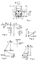
- Fig. 1 is a schematic diagram of a two-phase, two-pole AC induction motor comprising a stator 3 having two orthogonal stator windings 1, 2, a rotor in the nature of a squirrel cage rotor having a plurality of rotor windings 5, 6 each having a single short-circuited turn and two of which are shown in Fig. 1.
- Each phase operates as a transformer.
- Each stator winding 1, 2 is a primary winding with two tasks. It transforms a current to the secondary winding 5, 6 in the rotor, and it creates a magnetic stator field, with the components B1 and B2.
- the motor has a symmetrical design. All phases have equal value and must be controlled in the same way , however, with 90° mutual phase angle. Consequently, it should be enough to study one phase. If one phase is correctly controlled, and the other phase is controlled in the same way, the whole motor must operate correctly. This important observation greatly simplifies the theory.
- the system model can be reduced from a two-dimensional geometrical system to a one-dimensional system during the initial studies.
- the control strategy will be: Study phase 1 and control the rotor current, which creates the torque. This is the primary purpose of the control system. Make sure that phase 1 simultaneously generates a correct magnetic field. The field is necessary for phase 2. If phase 2 is controlled by the same rules, phase 1 will be sure to receive a field from phase 2.
- FIG. 2 shows the conventional transformer model of one phase of the AC induction motor comprising a stator terminal 7, a main inductance 8, a stator resistance 9, a rotor resistance 10 and a counter EMF 11.
- the leakage inductances have been neglected, and are not shown. They can be included in the model later.
- the broken lines 48 symbolize the airgap between rotor and stator.
- the model is conventionally defined with a transformation ratio of 1:1 between stator and rotor circuits.
- a current Im through the main inductance creates a magnetic field, which passes through the stator and the rotor.
- a stator voltage V is connected to the stator terminal 7 resulting in a stator current Is.
- counter EMF U is modulated with the same phase angle as the airgap voltage E and the rotor current Ir.
- Both the magnetizing current Im and the rotor current Ir are functions of the airgap voltage E.
- the rotor current Ir shall always be controlled according to equation (4), either by a voltage or a current source, connected to the motor terminal 7. This is the primary control function.
- the magnetizing current Im shall always be controlled according to equation (5), by adjusting the frequency w. This is a secondary control function. For any given value of E, it is always possible to obtain the desired current Im by adjusting the frequency w. This will not change the rotor current Ir, which is entirely resistive and thus frequency independent.
- a negative value of w means that the field vector rotates in a negative direction.
- Decoupling and quadrature are the major features of conventional field oriented control. Here they are obtained in a natural way, almost automatically, if equation (6) is satisfied.
- decoupling by definition permits two degrees of freedom for controlling the two currents Im and Ir. By sacrificing the one degree of freedom, i.e. by keeping the magnetizing current Im constant, quadrature is obtained in exchange.
- Figs. 3, 4 and 5 are defined according to classical AC circuit theory with complex electrical vectors. Positive modulation is conventionally described by a counter-clockwise rotation of the whole diagram around the origin, with the vectors projected on the real axis.
- Fig. 3 defines the relationship between the airgap voltage vector E and the current vectors Im and Ir from Fig. 2. Also the total stator current Is is shown.
- the airgap voltage E is used as reference vector arbitrarily defined in vertical direction.
- the currents are studied as functions of E according to equations (4) and (5) and not as functions of the terminal voltage V. This "trick" makes the mathematics and the vector diagram very simple. E and Ir have the same phase angle, and Im has 90° phase delay. It also makes it possible to define a control vector in a simple way.
- Fig. 4 is a voltage vector diagram of the circuit shown in Fig. 2, based on the vectors in Fig. 3.
- the resistive voltage drops in the stator resistance due to the currents Ir, Im have been added to the airgap voltage E.
- the terminal voltage vector V is obtained as the sum of all vector components.
- V voltage vector
- Equations (8) and (9) describe the drive voltages for a two-phase motor.
- the new vector (Sm, Sr) is stationary in relation to the rotating field in the motor, or in other words "synchronized" to the rotating field.
- the vector components Sm and Sr are created by the control system as DC values and shall be connected as control signals to a vector rotator, which transforms them from field coordinates to stator coordinates, creating an output vector (V1, V2) as two components V1 and V2 with AC values, before they are connected to frequency inverters and the stator windings.
- the angle ⁇ is positive in counter-clockwise direction, starting from the horizontal axis (the real axis in a complex diagram).
- Equations (8) and (9) were taken directly from Fig. 4b but the same result can be obtained by the conventional method in classical AC circuit theory:
- V1 Re
- Sm1 cos wt - Sr1 sin wt
- V2 Re
- Sm2 sin wt + Sr2 cos wt
- Th complex vectors (Sm1 + j Sr1) and (Sr2 - j Sm2) are defined by Fig. 5.
- equations (8) and (9) or (18) and (19) as two individual voltages and of equations (16) and (17) as one geometrical voltage vector in the stator plane gives the same result.
- the geometrical vector V can be represented by vector V1 in Fig. 5. In this case vector V2 is excluded.
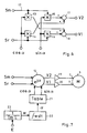
- Fig. 6 is a block diagram, showing the mathematical functions in a conventional vector rotator 12, according to equations (16) and (17). For two phases, there are four multiplying circuits (13 - 16) and two summing circuits 17, 18. The input vector (Sm, Sr) is rotated with angle ⁇ and the output vector is (V1, V2).
- Fig. 7 shows the central structure of a control system according to the present invention, with a control vector (Sm, Sr) in field coordinates connected to a vector rotator 12 and an output vector (V1, V2) in stator coordinates, connected to a motor 3.
- a control vector Sm, Sr
- V1, V2 output vector
- power stages 19 19, 20 frequency inverters
- they are assumed to be ideal elements, operating either as voltage sources or current sources.
- the vector rotator 12 is controlled by signals (sin ⁇ , cos ⁇ ) from a trigonometrical table 21.
- the input angle ⁇ to the table 21 comes from an integrator 22, which integrates the input frequency w and delivers the output angle ⁇ , which is the time integral of the frequency w.
- the angle ⁇ is equal to wt for steady state operation with constant w and sinusoidal signals.
- Block 23 calculates the rotation frequency w as a function of an estimated airgap voltage E* according to equation (6).
- the integrator 22 may have a certain input offset resulting in an output drift. This is no problem as long as the drift error is sufficiently small.
- the integrator is a "modulo-2 ⁇ " integrator which integrates in a tangential direction around a unit circle, and it can never come to an end stop. In a practical system the integrator may be a binary up-down counter, which counts upwards to its maximum value and then continues directly to zero on the next count, and similarly in the downward direction.
- the sign of the estimated value E* can be positive as well as negative. It depends on the operating conditions.
- the sign of E* determines the direction of rotation of the vector rotator.
- the described method for frequency generation keeps the magnetizing current (Im) constant.
- the rotor circuit is entirely resistive and thus insensitive to frequency variations. Thanks to this, there is no interaction from the magnetizing circuit to the rotor circuit. And conversely, the magnetizing circuit is not disturbed by the rotor circuit and variations in E. Actually, the magnetizing current has been "compensated” for variations in E. Thus, the system permits “decoupled” control of the rotor current and the magnetizing current.
- the control system according to the present invention is based on estimation of the airgap voltage amplitude E*.
- Other solutions for field orientation have been tried, where the airgap voltage En* in each individual phase is estimated and then integrated in order to create an estimate of the magnetic field.
- Such solutions suffer from a problem with integrator offset and drift, and consequently they cannot be used down to zero frequency.
- the present solution doesn't suffer from this problem.
- Control problem A has been solved. It remains to generate a control vector.
- the rotor current Ir in Fig. 2 is controlled by the airgap voltage E, regardless of how this voltage is created. Consequently, the motor can be controlled at the terminal 7 by voltage source frequency inverters as well as current source frequency inverters.
- the total control vector shall be generated as the sum of two orthogonal components Sm and Sr, according to equation (7) and the same as in the Swedish patent No. 8000118.
- Sm is normally constant and represents the voltage drop in the stator resistance, caused by the constant magnetizing current.
- Sr is the active control variable. It controls the motor and primarily the rotor circuit, exactly as if it was a DC motor.
- Sr is composed of the voltage drop in the stator resistance caused by the rotor current, plus the airgap voltage E.
- the airgap voltage E is composed of the voltage drop in the rotor resistance caused by the rotor current, plus the counter EMF U.
- the constant Im in block 23 has the same value as the constant Im in equation (7) and represents the desired magnetizing current, which according to the present invention should be constant.
- Fig. 8 shows a complete control system according to the present invention for Natural Field Orientation, based on the block diagram in Fig. 7. For simplicity block 21 is not shown.
- the phase voltages V1, V2 at the motor terminals 7 are measured by measuring devices 24, 25 and the phase currents Is1, Is2 are measured by measuring devices 26, 27 and connected to a calculating block 28.
- E1* and E2* are AC values and cannot conveniently be used directly for calculating the rotation frequency w.
- values E1*, E2* are regarded as a rotating airgap voltage vector (E1* + j E2*) which is then transformed from stator coordinates to field coordinates in a vector counterrotator 29 rotating in the opposite direction as vector rotator 12.
- the output signals from the counterrotator 29 is a stationary airgap voltage vector (Em*, Er*) which should be parallel with Sr.
- Em* should be zero and is regarded as an error signal defined as ⁇ .
- the airgap voltage vector component Er* is equalled to E* and is used as input signal to calculation block 23 for calculating the rotation frequency w.
- signal E* shall be identical with the vector E in Fig. 4 and the signal " ⁇ " shall be zero.
- the vector E as well as the estimated signal E* can be positive or negative.
- the estimated values E1* and E2* are instantaneous values and thus modulated
- the transformed value E* has a constant amplitude without ripple.
- the vector counterrotator 29 may be described as a "synchronized demodulator". It is based on a multi-phase system. It wouldn't work in a one-phase system.
- the counter EMF U in phase 1 is proportional to the product of the rotor speed and the magnetic field from phase 2.
- the field in phase 2 is modulated with the same phase angle as the airgap voltage in phase 1.
- the voltages U and E in Fig. 2 are modulated with the same phase angle. They would be parallel in a vector diagram.
- This version of the control system is essentially an improved version of the control system according to the Swedish patent No. 8000118, based on a different measuring system, but still with Natural Field Orientation.
- the control characteristics are the same as for a voltage controlled DC motor.
- the control signal (Sr) essentially controls the rotor circuit and thus the speed.
- the system in Fig. 8 operates with Natural Field Orientation.
- the voltage control vector (Sm, Sr) is connected to the vector rotator for conversion from field coordinates to stator coordinates.
- the control vector is not "synchronized" to the field by help of field measurements. Instead, the rotation of the vector rotator is controlled by the magnetizing circuit.
- the complete motor control system will automatically synchronize itself and create stable operating conditions. This is a great advantage with the AC induction motor. It is not necessary to know the rotor position. A magnetic field will be generated anywhere in the motor when the system is energized. Then the operation will continue from this initial value.
- the vector component Sr can be used as a control signal, always with correct field orientation, i.e. with quadrature between the magnetizing current Im and the voltage Sr.
- the control system can be described as an open loop control system. Optimal control signals Sm, Sr and w are generated and then the system "trusts" that the motor will operate correctly. The system relies on stable motor parameters, essentially on the stability of the main inductance L.
- Natural Field Orientation is obtained by help of a constant magnetizing current. This is the most important parameter to control.
- the control system for Im can be studied and described from several different points of view.
- the magnetizing current Im is controlled by a closed loop system according to Fig. 8.
- the airgap voltage E is measured and used for calculation of an optimal frequency w, which is intended to keep the magnetizing current Im constant.
- the magnetizing current is never directly measured and controlled by a feedback loop. Consequently, this is also an open loop control system for magnetizing current.
- the explanation is that the magnetizing current depends on two variables, E and w, according to equation (5). Thus there are two degrees of freedom, and this requires two control loops.
- the closed loop according to the present invention generates a fixed relation between E and w. Then the numerical value of this relation defines the current Im according to equation (5), and this is the open loop control.
- the current depends on the value of the main inductance L. A variation of L gives a current change. This is characteristic for open loop control.
- the main and only purpose of the closed loop in Fig. 8 is to make the magnetizing current Im independent of the airgap voltage E.
- the quotient between E and w will be correct for all values of E, thanks to the closed control loop.
- the loop works as a compensation for external disturbances, represented by the airgap voltage E. This is important, because the airgap voltage E is also part of the rotor circuit and changes within a very large range.
- Fig. 9 shows an alternative version of the control system according to Fig. 8 in which current source inverters are used.
- the same designation numerals are used in Fig. 9 as in Fig. 8 for the same components.
- the control signal is a current vector (Im, Ir) and the vector rotator output signals are fed to current source frequency inverters 30, 31.
- the operation of the measuring system according to the invention is identical to Fig. 8 and the generation of the rotation frequency takes place in the same way. It is observed that the constant Im in block 23 has the same value as the control variable Im fed to the vector rotator 12 and represents the desired magnetizing current, which according to the present invention should be constant.
- the control signal Ir is the real control variable. Ir controls the motor, and primarily the rotor circuit, exactly as if it was a DC motor.
- the control characteristics are the same as for a current controlled DC motor.
- the rotor current Ir controls the torque.
- the system will automatically synchronize and operate with correct field orientation, also in this case with Natural Field Orientation.
- the current source frequency inverters will deliver the desired currents to the motor windings.
- the currents must flow through the winding impedances.
- the currents will create a voltage vector in the motor, which is the same as if the motor was controlled by a voltage source frequency inverter.
- a current source has certain advantages. It permits direct control of the rotor current, and thus direct torque control.
- a good current source can deliver the desired current, independent of the circuit impedance. Thus the current source can "eliminate” or overcome the influence of the motor's leakage inductances. Further, the current source will deliver the desired current, independent of the resistance in the stator and rotor circuit.
- this version of the control system is essentially an improved version of the control system according to the Swedish patent No. 8000118, based on a different measuring system, but still with Natural Field Orientation.
- current source frequency inverters are used instead of voltage source frequency inverters, and this is an important improvement.
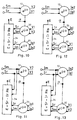
- Fig. 10 shows a different version of the control system according to Fig. 8 in which each measured quantity V1*, V2*, Is1*, Is2* is separately counterrotated by two counterrotators, the first of which 32 counterrotates the voltages and outputs the voltage vector (Sm*, Sr*) and the second of which 33 counterrotates the currents and outputs the current vector (Im*, Ir*).
- Equation (22) can be obtained from Fig. 4.
- signals Sr, Sm already exist in field coordinates and thus it is not necessary to counterrotate said signals but they can be taken directly from the input to the vector rotator 12 as shown in Fig. 11. It is also noted that signals Sm* and Im* are not used in calculating block 34, and thus said signals represent redundant information which can be used for other purposes, see below.
- Fig. 12 shows another different version of the control system according to Fig. 9 in which each measured quantity V1*, V2*, Is1*, Is2* is separately counterrotated by two counterrotators, the first of which 32 counterrotates the voltages and outputs the voltage vector (Sm*, Sr*) and the second of which 33 counterrotates the currents and outputs the current vector (Im*, Ir*) similar to Fig. 10 but with current source frequency inverters 30, 31. Said voltage vector (Sm*, Sr*) and said current vector (Im*, Ir*) are fed to calculating block 34 as in Fig. 10.
- signals Ir, Im already exist in field coordinates and thus it is not necessary to counterrotate said signals but they can be taken directly from the input to the vector rotator 12 as shown in Fig. 13. It is also noted that signals Sm* and Im* are not used in calculating block 34, and thus said signals represent redundant information, see below.
- the accuracy of the control system according to the present invention relies on a true measurement or estimation of the airgap voltage.
- the stator resistance and the leakage inductance, see below
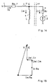
- Fig. 14 shows a commonly used motor model including a single leakage inductance 35.
- the rotor leakage inductance (not shown) has been transformed to the stator side and added to the stator leakage inductance, resulting in one single leakage inductance 1.
- the other parameters of the motor model also are influenced upon by the transformation of the rotor leakage inductance to the stator side, and the model values are adjusted in accordance therewith when the effect of the leakage inductance is introduced in the motor model, see for example "Introduction to Field Orientation and High Performance AC Drives", chapter 2.6 - 2 "Modified Equivalent Circuit", Novotny - Lorenz, 1986 IEEE Industry Applications Society Annual Meeting.
- Figs. 14 and 15 are defined with electrical vectors according to classical AC circuit theory.
- Equations (23) and (24) are more accurate than equations (20) and (21) and are preferred.
- the calculated vector (E1*, E2*) is connected to the second vector counterrotator 29 in Fig. 8 or Fig. 9. This counterrotator is controlled by the same angle - ⁇ as the first vector rotator 12, although in opposite direction.
- V ⁇ Rs Im ⁇ + Rs Ir ⁇ + jwl Im ⁇ + jwl Ir ⁇ + E ⁇
- Fig. 15 shows the vector V , according to equation (25).
- An improved control system can be designed with compensation for the leakage inductance by help of a correction term (- wl Ir) which is added to the original signal Sm.
- the necessary signal Ir can be obtained from the measuring system, by help of an addition to Fig. 8 similar to Fig. 10.
- Fig. 14 shows the leakage inductance l in series with the stator resistance Rs.
- An ideal motor would have zero leakage inductance. This is not possible to obtain, but it is possible to design a voltage source frequency inverter with negative output inductance, intended to cancel the effect of the motor's leakage inductance. This is described in the Swedish patent application No. 8902883-1.
- Such frequency inverters can be used together with a control system according to the present invention.
- the vector diagram in Fig. 4 will be valid also for the real motor including the leakage inductance, and the signals Sr and Sm can be generated according to this diagram.
- the calculation of airgap voltage according to equations (23) and (24) should still be used.
- the leakage inductance in Fig. 14 will not disturb the control system, as can be proved by the following simple reasoning.
- the current sources are assumed to be "ideal” and deliver the correct currents independent of the circuit impedance.
- the total current Is will be divided in two components, magnetizing current Im and rotor current Ir.
- the airgap voltage E is measured and used for control of the magnetizing current, according to the present invention.
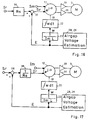
- Fig. 16 shows another system according to the present invention which is basically the same system as in Fig. 8. However, an external control signal Ir is used instead of the control signal Sr.
- This converted version makes it possible to control the rotor current by the external control signal Ir, although the motor is voltage controlled and has voltage source frequency inverters. However, the influence of the leakage inductances is not eliminated. It is not a "true" current control system.
- the control characteristics are essentially the same as for a current controlled DC motor.
- the control signal Ir controls the torque.
- Fig. 17 shows another system according to the present invention which is basically the same system as in Fig. 9.
- An external control signal Sr is used instead of the control signal Ir.
- This converted version makes it possible to control the rotor voltage by the external signal Sr, although the motor is current controlled by current source frequency inverters.
- the influence of the leakage inductances is partly eliminated by the current source frequency inverters.
- the control characteristics are the same as for a voltage controlled DC motor.
- the rotor voltage controls essentially the speed.
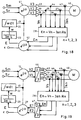
- Figs. 18 and 19 show systems with three-phase motors 40. Except for the three phases, the systems are identical with the system in Fig. 8. A similar conversion to three phases (not shown) can be made for the system in Fig. 9.
- the vector rotator 41 has a three-phase output and the vector counterrotator 42 has a three-phase input.
- An extra frequency inverter 43 is needed for the third phase, as well as extra measuring means for voltage 44 and current 45.
- the control system measures the airgap voltage vector E, which is a two-dimensional quantity, defined for example in polar coordinates by an amplitude and an angle.
- the system needs only the amplitude of this vector, converted to field coordinates.
- the system doesn't use the information about the vector angle. This is a redundant information, which can be used for automatic parameter adaptation according to the following description.
- the angle of the vector E in the real motor shall be parallel with the "commanded" vector E, which is parallel with the control signal Sr.
- a parallelity error indicates an error in the system.
- the two vector rotators are controlled by the same rotation angle ⁇ , although in opposite directions. The effects cancel each other.
- the two output signals ( ⁇ , E) of the counterrotator 29 are parallel with the two control signals (Sm, Sr) to the first vector rotator 12.
- the measured vector (E1*, E2*), transformed to field coordinates shall be parallel with the E* output. Any angular error in the measured vector will give a contribution on the ⁇ output, which thus indicates an error.
- Said error signal may be used for parameter adaption of the model values of the motor.
- Errors are defined as the difference between the assumed component values in the system model and the real component values in the motor.
- the stator resistance Rs may be adapted at zero speed (or low speed) operation. Assume motor operation with no load and zero speed, for example immediately after power turn-on.
- the input signal Sr is zero.
- the frequency w is zero and the airgap voltage E is zero.
- the rotor current Ir is zero, but the magnetizing current Im shall have its nominal value. This is true DC operation and thus all voltage and current components are parallel with Sm.
- the circuit for estimation of the airgap voltage calculates the vector (E1*, E2*) according to equations (20) and (21).
- This estimated vector shall be zero. If not, an error component will appear on the output ⁇ from the vector rotator. The error depends on a wrong value of Rs in the system model in one or both phases.
- the signal on the output ⁇ can be used as an error signal (plus or minus), which adjusts Rs up or down until the error signal ⁇ is zero.
- an adjustment of the value Rs can be made individually in each phase according to equations (20) and (21), if the calculation and correction is made in block 28, Figs. 8 and 9. However, in this case the adjustment must be made during DC-conditions, and ideally when the magnetizing current Im has its maximum value in each phase. Thus the vector rotator should be rotated 90° between the two measurements and adjustments (or 120° and 240° for three-phase operation).
- the main inductance L can be adjusted at high speed operation. This method can be used only when Rs has been adjusted to a correct value.
- the main inductance L is assumed to have the same value in all phases.
- the magnetizing current Im depends essentially on the main inductance L.
- An error in the model value of L gives an error in the magnetizing current Im. Since the magnetizing current gives a voltage drop in the stator resistance Rs, a current error will give a voltage drop error in the stator resistance. This error is parallel with the voltage Sm, and will appear in the output ⁇ from the vector rotator.
- the signal on the output ⁇ can be used as an error signal (plus or minus), which adjusts L down or up until the error signal on ⁇ is zero.
- the two methods can be used alternatively, depending on the motor's actual operation conditions.
- a small Sr signal indicates that the first method should be used, and a larger Sr signal indicates that the second method should be used. It is also possible to use the two methods simultaneously, in a system where the two methods are added with different weighting factors, depending on the operating conditions.
- the inductance L is a stable parameter, and an initial adjustment during the first start of a system may be enough. Then the first method can be used continuously at all speeds, thus compensating for variations in the stator resistance when the motor temperature changes.
- An additional method is to have a temperature sensor in the motor stator, and make temperature compensation of Rs based on the measured temperature.
- the leakage inductances have been neglected so far. It has been shown that the most important parameter adjustment occurs during DC conditions (the first method), when the leakage inductances have zero impedance, and really are neglectable.
- the parameter adjustment is important.
- the magnetizing current is controlled essentially by the stator resistance at low frequencies, and essentially by the main inductance at high frequencies.
- a correct adjustment guarantees that the magnetizing current will remain correct during all operating conditions, also during dynamic conditions with quick changes between high and low speed.
- the quadrature, and consequently the Natural Field Orientation will remain correct all the time.
- This value of U* is proportional to the rotor speed and can be used as a "synthetic" (or estimated) tachometer signal in a speed control loop. However, it is not as accurate as a real tachometer signal.
- the current Ir* is proportional to the motor torque, and can be used in a torque control loop, for example together with the systems in Figs. 10 or 11.
- the frequency inverters are assumed to be “ideal” according to the present description (see the description of Fig. 7). It is not necessary for the operating principle to have “ideal" frequency inverters. Also simpler inverters, for example thyristor frequency inverters with a relatively low switching freqency, can be used in a motor control system according to the present invention.
- a control system according to the present invention can be designed with any type of electrical circuits, such as analog or digital circuits or any mix of such circuits.
- a vector counterrotator is used in the present description for transforming the estimated airgap voltage from stator coordinates to field coordinates.
- the output E from the vector rotator represents the stationary airgap voltage vector in field coordinates. It is not necessary to use a vector rotator.
- the absolute value of the vector can be calculated as:
- (E1*)2+ (E2*)2 If the rotation vector E has a constant amplitude, this calculated value will be a constant value without ripple, also for low frequencies down to zero frequency.
- phase sensitive rectifier may be used for this purpose, in addition to or in combination with the above computation formulas, or together with other formulas.
- the PCT patent application PCT/SE88/00124 discloses an improvement of the original control system according to Swedish patent No. 8000118.
- the non-linear magnetization characteristics of the stator and rotor iron can be compensated by a simple addition to the control system.
- the modulation in vector rotator 12, blocks 13 and 15 of the voltage component Sm is made with a modified sine and cosine function, intended to compensate for the nonlinear voltage drop in stator resistance Rs caused by the nonlinear magnetizing current.
- This improvement can also be used together with the present control system, for voltage source frequency inverters as well as current source frequency inverters.
- the magnetizing current Im should be modulated in vector rotator 12, blocks 13 and 15 with a modified sine and cosine function.
- the four systems according to the present invention are based on airgap voltage measurement. Thus the need for a speed sensor on the rotor shaft is eliminated.
- the system with current source frequency inverters controls the motor torque, and the system with voltage source frequency inverters controls essentially the motor speed.
- the system with voltage source frequency inverters controls essentially the motor speed.
- control characteristics can be changed and improved by external control loops, for example with tachometer or position feedback loops. This is made according to conventional control theory and is not described here.
- the airgap voltage can be measured by special measuring windings in the motor.
- the windings measure the induced voltage in the airgap, caused by the magnetic airgap field.
- the rotor field which is equivalent with the airgap field in a motor model with the rotor leakage inductance transformed to the stator side.
- the measuring winding measures the true airgap field.
- the measured result must be compensated by a compensation term proportional to the stator current.
- This is a wellknown compensation method in systems which use measuring windings or magnetic Hall sensors in the airgap of the motor, see for example the mathematical motor model in the paper "Natural Field Orientation, a New Voltage Control System for the AC Induction Motor", Ragnar Jönsson, Conference proceedings of PCIM Intelligent Motion Conference, October 1989, Long Beach, California, USA.
Landscapes
- Engineering & Computer Science (AREA)
- Power Engineering (AREA)
- Control Of Ac Motors In General (AREA)
Claims (10)
- Système de commande pour moteur (M) à induction à courant alternatif pour la commande orientée de champ, comprenant un stator (3), un rotor (4), au moins deux enroulements de stator (1, 2) et enroulements de rotor (5, 6), ledit système de commande comprenant des signaux de commande (Sm, Sr), un premier rotateur vectoriel (12) pour faire tourner lesdits signaux de commande d'un premier angle (α) pour la conversion des coordonnées de champ en coordonnées de stator afin de fournir des signaux de sortie (V1, V2) connectés à des inverseurs de fréquences (19, 20) afin de fournir des signaux d'entraînement à chaque enroulement de stator (1, 2) du moteur, ledit premier angle (α) étant obtenu en intégrant une fréquence de rotation (w) au moyen de moyens d'intégration (22), ladite fréquence de rotation (w) étant commandée essentiellement pour maintenir constant un courant de magnétisation (Im) de chaque enroulement de stator (1, 2),
caractérisé par
un moyen (24, 25, 26, 27) pour mesurer des tensions et/ou des courants desdits signaux d'entraînement ou un enroulement de mesure pour mesurer une tension d'entrefer (E) ;
au moins un second rotateur vectoriel (29, 32, 33) pour faire tourner en sens inverse lesdites tensions et/ou courants ou une combinaison de ceux-ci ou une tension d'entrefer (E) d'un second angle (-α) qui est l'inverse du premier angle (α) pour la conversion des coordonnées de stator en coordonnées de champ ;
un moyen pour déterminer une tension estimée d'entrefer (E*) sur la base desdites tensions et/ou courants ou une combinaison de ceux-ci ou une tension d'entrefer (E) mesurés et tournés en sens inverse ;
un moyen (23) pour déterminer ladite fréquence de rotation (w) sur la base de ladite tension estimée d'entrefer (E*) essentiellement pour maintenir constante l'amplitude desdits courants de magnétisation (Im) de chaque enroulement de stator. - Système de commande selon la revendication 1, caractérisé par
un moyen (24, 25, 26, 27) pour mesurer à la fois lesdites tensions et lesdits courants desdits signaux d'entraînement ;
un moyen de calcul (28) pour calculer les tensions d'entrefer (E1*, E2*...) pour chaque enroulement de stator selon les formules :

ledit signal de commande (E*) commandant ladite fréquence de rotation (w) ; et oùE1* = la tension d'entrefer estimée pour le premier enroulement de statorE2* = la tension d'entrefer estimée pour le second enroulement de statorV1* = la tension d'entraînement de stator mesurée du premier enroulement de statorV2* = la tension d'entraînement de stator mesurée du second enroulement de statorIs1* = le courant d'entraînement de stator mesuré du premier enroulement de statorIs2* = le courant d'entraînement de stator mesuré du second enroulement de statorRs = la résistance nominale de stator pour chaque enroulement. - Système de commande selon la revendication 1, caractérisé par
un moyen (24, 25, 26, 27) pour mesurer à la fois lesdites tensions et lesdits courants desdits signaux d'entraînement ;
un moyen de calcul (28) pour calculer les tensions d'entrefer (E1*, E2*...) pour chaque enroulement de stator selon les formules :

ledit signal de commande (E*) commandant ladite fréquence de rotation (w) ; et oùE1* = la tension d'entrefer estimée pour le premier enroulement de statorE2* = la tension d'entrefer estimée pour le second enroulement de statorV1* = la tension d'entraînement de stator mesurée du premier enroulement de statorV2* = la tension d'entraînement de stator mesurée du second enroulement de statorIs1* = le courant d'entraînement de stator mesuré du premier enroulement de statorIs2* = le courant d'entraînement de stator mesuré du second enroulement de statorRs = la résistance nominale de stator pour chaque enroulement.s = l'opérateur de Laplacel = l'inductance nominale totale de fuite pour chaque enroulement de stator, l'inductance de fuite du rotor étant transformée du côté du stator et ajoutée à l'inductance de fuite du stator. - Système de commande selon la revendication 2 ou 3, caractérisé par un moyen (23) pour calculer ladite fréquence de rotation (w) selon la formule :


L = l'inductance principale de chaque enroulement de stator, définie pour un modèle de moteur dont l'inductance totale de fuite est du côté du stator
Im = le courant désiré de magnétisation. - Système de commande selon la revendication 4, caractérisé en ce que les signaux de commande vers ledit système de commande sont deux signaux de commande de tension (Sm, Sr), ledit premier signal de commande (Sm) étant essentiellement engendré selon la formule

- Système de commande selon la revendication 4, caractérisé par
lesdits signaux de commande vers ledit système de commande étant un signal de commande de courant unique (Ir) représentant le courant de rotor désiré ; un moyen (36) pour multiplier ledit signal de commande (Ir) par une constante (Rs) dans un circuit multiplicateur et un moyen (37) pour ajouter le signal de commande de sortie mesuré (E*) afin de fournir un second signal de commande (Sr) au premier rotateur vectoriel (12) ; un premier signal de commande (Sm) étant fourni au rotateur vectoriel, qui est retardé de 90° par rapport audit second signal de commande (Sr) par ledit premier rotateur vectoriel (12), ledit premier signal de commande (Sm) étant essentiellement engendré selon la formule Sm = Im Rs ; lesdits inverseurs de fréquence (19, 20) étant d'un type à source de tension (figure 16), ou
ledit signal de commande vers ledit système de commande étant un signal de commande de tension unique (Sr), un moyen (38) pour soustraire le signal de commande de sortie mesuré (E*) dudit signal de commande (Sr) et multiplier (39) le résultat (Sr - E*) par l'inverse de la résistance de stator (1/Rs) pour fournir un second signal de commande (Ir) au premier rotateur vectoriel (12) ; un premier signal de commande (Im) étant fourni au premier rotateur vectoriel (12) qui est retardé de 90° par rapport audit second signal de commande (Ir) par ledit premier rotateur vectoriel (12), ledit premier signal de commande étant essentiellement le courant de magnétisation désiré (Im) ; lesdits inverseurs de fréquence (30, 31) étant d'un type à source de courant (figure 17). - Procédé de commande pour moteur (M) à induction à courant alternatif pour la commande orientée de champ, comprenant un stator (3), un rotor (4), au moins deux enroulements de stator (1, 2) et enroulements de rotor (5, 6), au moyen d'un système de commande comprenant des signaux de commande (Sm, Sr), un premier rotateur vectoriel (12) pour faire tourner lesdits signaux de commande d'un premier angle ( α) pour la conversion des coordonnées de champ en coordonnées de stator afin de fournir des signaux de sortie (V1, V2) connectés à des inverseurs de fréquences (19, 20) afin de fournir des signaux d'entraînement à chaque enroulement de stator (1, 2) du moteur, ledit premier angle ( α) étant obtenu en intégrant une fréquence de rotation (w) au moyen de moyens d'intégration (22), ladite fréquence de rotation (w) étant commandée essentiellement pour maintenir constant un courant de magnétisation (Im) de chaque enroulement de stator (1, 2),
caractérisé en ce que
on mesure des tensions et/ou des courants desdits signaux d'entraînement ou on mesure une tension d'entrefer (E) ;
on fait tourner en sens inverse lesdites tensions et/ou courants ou une combinaison de ceux-ci ou une tension d'entrefer (E) par au moins un second rotateur vectoriel (29, 32, 33) d'un second angle (- α) qui est l'inverse du premier angle ( α) pour la conversion des coordonnées de stator en coordonnées de champ ;
un moyen pour déterminer une tension estimée d'entrefer (E*) sur la base desdites tensions et/ou courants ou une combinaison de ceux-ci ou une tension d'entrefer (E) mesurés et tournés en sens inverse ;
on détermine ladite fréquence de rotation (w) sur la base de ladite tension estimée d'entrefer (E*) essentiellement pour maintenir constante l'amplitude desdits courants de magnétisation (Im) de chaque enroulement de stator. - Procédé selon la revendication 7, caractérisé en ce que
on mesure à la fois lesdites tensions et lesdits courants desdits signaux d'entraînement ;
on calcule les tensions d'entrefer (E1*, E2*...) pour chaque enroulement de stator selon les formules :

on calcule ladite fréquence de rotation (w) selon la formule :
 E1* = la tension d'entrefer estimée pour le premier enroulement de statorE2* = la tension d'entrefer estimée pour le second enroulement de statorV1* = la tension d'entraînement de stator mesurée du premier enroulement de statorV2* = la tension d'entraînement de stator mesurée du second enroulement de statorIs1* = le courant d'entraînement de stator mesuré du premier enroulement de statorIs2* = le courant d'entraînement de stator mesuré du second enroulement de statorRs = la résistance nominale de stator pour chaque enroulement.L = l'inductance principale de chaque enroulement de stator, défini pour un modèle de moteur dont l'inductance totale de fuite est du côté du statorIm = le courant désiré de magnétisation.
 - Procédé selon la revendication 7, caractérisé en ce que
on mesure à la fois lesdites tensions et lesdits courants desdits signaux d'entraînement ;
on calcule les tensions d'entrefer (E1*, E2*) pour chaque enroulement de stator selon les formules :

on calcule ladite fréquence de rotation (w) selon la formule :
 E1* = la tension d'entrefer estimée pour le premier enroulement de statorE2* = la tension d'entrefer estimée pour le second enroulement de statorV1* = la tension d'entraînement de stator mesurée du premier enroulement de statorV2* = la tension d'entraînement de stator mesurée du second enroulement de statorIs1* = le courant d'entraînement de stator mesuré du premier enroulement de statorIs2* = le courant d'entraînement de stator mesuré du second enroulement de statorRs = la résistance nominale de stator pour chaque enroulement.L = l'inductance principale de chaque enroulement de stator, défini pour un modèle de moteur dont l'inductance totale de fuite est du côté du statorIm = le courant désiré de magnétisation.s = l'opérateur de Laplacel = l'inductance nominale totale de fuite pour chaque enroulement de stator, l'inductance de fuite du rotor étant transformée du côté du stator et ajouté à l'inductance de fuite du stator.
 - Procédé selon la revendication 8 ou 9, caractérisé en ce que
ledit second rotateur vectoriel (29) fait tourner lesdites tensions d'entrefer (E1*, E2*...) en sens inverse pour fournir un signal de commande de sortie (E*) qui représente la tension d'entrefer dans les coordonnées de champ et un signal d'erreur (ε) en coordonnées de champ,
on fait fonctionner le système de commande et le moteur à vitesse faible ou nulle ; on ajuste une valeur modèle de la résistance de stator (Rs) jusqu'à ce que le signal d'erreur soit le plus petit possible et/ou
on fait fonctionner le système de commande et le moteur à vitesse élevée ; on ajuste une valeur modèle de l'inductance principale (L) jusqu'à ce que le signal d'erreur soit le plus petit possible.
Applications Claiming Priority (3)
| Application Number | Priority Date | Filing Date | Title |
|---|---|---|---|
| SE9000497 | 1990-02-12 | ||
| SE9000497A SE9000497L (sv) | 1990-02-12 | 1990-02-12 | Foerfarande och apparat foer reglering av en asynkronmotor genom indirekt maetning av luftgapsspaenningen |
| PCT/SE1991/000086 WO1991012656A1 (fr) | 1990-02-12 | 1991-02-08 | Procede et appareil de commande d'un moteur a induction a courant alternatif par mesurage indirect de la tension de l'entrefer |
Publications (2)
| Publication Number | Publication Date |
|---|---|
| EP0515469A1 EP0515469A1 (fr) | 1992-12-02 |
| EP0515469B1 true EP0515469B1 (fr) | 1994-08-31 |
Family
ID=20378533
Family Applications (1)
| Application Number | Title | Priority Date | Filing Date |
|---|---|---|---|
| EP91904122A Expired - Lifetime EP0515469B1 (fr) | 1990-02-12 | 1991-02-08 | Procede et appareil de commande d'un moteur a induction a courant alternatif par mesurage indirect de la tension de l'entrefer |
Country Status (9)
| Country | Link |
|---|---|
| US (1) | US5294876A (fr) |
| EP (1) | EP0515469B1 (fr) |
| JP (2) | JP3325886B2 (fr) |
| AT (1) | ATE110899T1 (fr) |
| AU (1) | AU7241091A (fr) |
| DE (1) | DE69103746T2 (fr) |
| ES (1) | ES2064087T3 (fr) |
| SE (1) | SE9000497L (fr) |
| WO (1) | WO1991012656A1 (fr) |
Cited By (1)
| Publication number | Priority date | Publication date | Assignee | Title |
|---|---|---|---|---|
| WO2005086340A1 (fr) * | 2004-03-10 | 2005-09-15 | Joensson Ragnar | Procede et systeme de commande pour moteur a induction ca |
Families Citing this family (24)
| Publication number | Priority date | Publication date | Assignee | Title |
|---|---|---|---|---|
| JPH05181503A (ja) * | 1991-12-27 | 1993-07-23 | Toyo Electric Mfg Co Ltd | 安定化フィードバック制御方法 |
| JP3064671B2 (ja) * | 1992-04-27 | 2000-07-12 | 富士電機株式会社 | 電力変換装置の制御回路 |
| JPH06178576A (ja) * | 1992-12-04 | 1994-06-24 | Toshiba Mach Co Ltd | 同期電動機の制御方法 |
| US5559419A (en) * | 1993-12-22 | 1996-09-24 | Wisconsin Alumni Research Foundation | Method and apparatus for transducerless flux estimation in drives for induction machines |
| US5585709A (en) * | 1993-12-22 | 1996-12-17 | Wisconsin Alumni Research Foundation | Method and apparatus for transducerless position and velocity estimation in drives for AC machines |
| US5708346A (en) * | 1994-01-10 | 1998-01-13 | Sulzer Electronics Ag | Method and control apparatus for controlling an AC-machine |
| FR2743456B1 (fr) * | 1996-01-04 | 1998-02-06 | Thomson Csf | Moteur electrique de type synchrone a aimants permanents et vehicule comportant un tel moteur |
| US5821725A (en) * | 1996-10-16 | 1998-10-13 | Industrial Technology Research Institute | Electric current compensation circuit for brushless motors for reducing ripples in output torques during phase change |
| TW393748B (en) * | 1997-08-22 | 2000-06-11 | Enomoto Kk | Manufacturing of semiconductor devices and semiconductor lead frame |
| US6078119A (en) * | 1997-11-26 | 2000-06-20 | Ebara Corporation | Bearingless rotary machine |
| DE19844050A1 (de) * | 1998-09-25 | 2000-03-30 | Abb Daimler Benz Transp | Verfahren zum Steuern und Regeln eines elektrischen Antriebes sowie Vorrichtung zur Durchführung des Verfahrens |
| US6069467A (en) * | 1998-11-16 | 2000-05-30 | General Electric Company | Sensorless rotor tracking of induction machines with asymmetrical rotor resistance |
| EP1284045A1 (fr) * | 2000-05-23 | 2003-02-19 | Vestas Wind System A/S | Eolienne a vitesse variable pourvue d'un convertisseur de matrice |
| US6664672B2 (en) | 2001-07-13 | 2003-12-16 | American Superconductor Corporation | Enhancement of stator leakage inductance in air-core machines |
| US7015595B2 (en) * | 2002-02-11 | 2006-03-21 | Vestas Wind Systems A/S | Variable speed wind turbine having a passive grid side rectifier with scalar power control and dependent pitch control |
| WO2003073185A2 (fr) * | 2002-02-28 | 2003-09-04 | Zetacon Corporation | Systeme et procede de commande predictive |
| CA2379732A1 (fr) * | 2002-04-02 | 2003-10-02 | Turbocor Inc. | Systeme et methode de commande d'un moteur electrique |
| US6756763B2 (en) * | 2002-05-02 | 2004-06-29 | Visteon Global Technologies, Inc. | Sensorless induction motor control |
| JP2004173422A (ja) * | 2002-11-20 | 2004-06-17 | Fanuc Ltd | 誘導電動機の制御装置 |
| US7116075B2 (en) * | 2003-10-31 | 2006-10-03 | Valeo Electrical Systems, Inc. | Electric power steering system for a vehicle |
| JP2005219133A (ja) * | 2004-02-03 | 2005-08-18 | Fanuc Ltd | ロボット用サーボモータ制御装置およびロボット |
| KR20130095819A (ko) * | 2010-12-06 | 2013-08-28 | 미쓰비시덴키 가부시키가이샤 | 동기 전동기의 인덕턴스 측정 장치 및 측정 방법 |
| KR101619567B1 (ko) * | 2012-11-09 | 2016-05-18 | 엘에스산전 주식회사 | 유도전동기의 파라미터 추정장치 |
| EP3979473A4 (fr) * | 2019-05-24 | 2022-06-08 | Mitsubishi Electric Corporation | Procédé de fabrication d'un moteur électrique, moteur électrique, compresseur, et climatiseur |
Citations (1)
| Publication number | Priority date | Publication date | Assignee | Title |
|---|---|---|---|---|
| WO1982001628A1 (fr) * | 1980-10-30 | 1982-05-13 | Ragnar Joensson | Procede et appareil de commande d'un moteur a induction a courant alternatif |
Family Cites Families (9)
| Publication number | Priority date | Publication date | Assignee | Title |
|---|---|---|---|---|
| DE2106789C3 (de) * | 1971-02-12 | 1978-03-02 | Siemens Ag, 1000 Berlin Und 8000 Muenchen | Einrichtung zur Steuerung oder Regelung des Ständerstromvektors einer Asynchronmaschine |
| DE2833542C2 (de) * | 1978-07-31 | 1980-09-25 | Siemens Ag, 1000 Berlin Und 8000 Muenchen | Drehfeldmaschinenantrieb, bestehend aus einer umrichtergespeisten Drehfeldmaschine, insbesondere Synchronmaschine und einer Stromrichtersteuerung für den eigengetakteten, insbesondere feldorientierten Betrieb dieser Maschine, mit zwei baugleichen Wechselspannungsintegratoren und Verfahren zum Betrieb des Drehfeldmajchinenantriebes |
| SE420141B (sv) * | 1980-01-08 | 1981-09-14 | Ragnar Georg Jonsson | Sett och anordning for styrning av en vexelstroms asynkronmotor |
| DE3034252A1 (de) * | 1980-09-11 | 1982-04-15 | Siemens AG, 1000 Berlin und 8000 München | Vorrichtung zum feldorientierten betrieb einer umrichtergespeisten asynchronmaschine |
| NO851324L (no) * | 1984-05-18 | 1985-11-19 | Siemens Ag | Fremgangsmaate og anordning til aa bestemme en dreiefelt-maskins fluksvektor. |
| EP0228535A1 (fr) * | 1985-12-04 | 1987-07-15 | Siemens Aktiengesellschaft | Méthode et appareil pour la détermination de l'angle de flux d'une machine à induction et d'autre part pour le fonctionnement de la machine en orientation de position |
| EP0274716A1 (fr) * | 1987-01-09 | 1988-07-20 | Siemens Aktiengesellschaft | Méthode et appareil à déterminer le vecteur de flux d'une machine à induction |
| SE8701008L (sv) * | 1987-03-11 | 1988-09-12 | Ragnar Jonsson | Forbettrat reglerforfarande for en vexelstromsinduktionsmotor och anordning dertill |
| FI884512A (fi) * | 1987-11-25 | 1989-05-26 | Siemens Ag | Foerfarande foer efterbildning av en belastningsvinkels nuvaerde hos en vridfaeltsmotor samt ett kopplingsschema foer foerverkligande av detta foerfarande. |
-
1990
- 1990-02-12 SE SE9000497A patent/SE9000497L/ not_active Application Discontinuation
-
1991
- 1991-02-08 EP EP91904122A patent/EP0515469B1/fr not_active Expired - Lifetime
- 1991-02-08 AU AU72410/91A patent/AU7241091A/en not_active Abandoned
- 1991-02-08 DE DE69103746T patent/DE69103746T2/de not_active Expired - Fee Related
- 1991-02-08 JP JP50430291A patent/JP3325886B2/ja not_active Expired - Fee Related
- 1991-02-08 WO PCT/SE1991/000086 patent/WO1991012656A1/fr active IP Right Grant
- 1991-02-08 ES ES91904122T patent/ES2064087T3/es not_active Expired - Lifetime
- 1991-02-08 AT AT91904122T patent/ATE110899T1/de not_active IP Right Cessation
- 1991-08-02 US US07/920,310 patent/US5294876A/en not_active Expired - Lifetime
-
2000
- 2000-11-22 JP JP2000356368A patent/JP2001245500A/ja active Pending
Patent Citations (1)
| Publication number | Priority date | Publication date | Assignee | Title |
|---|---|---|---|---|
| WO1982001628A1 (fr) * | 1980-10-30 | 1982-05-13 | Ragnar Joensson | Procede et appareil de commande d'un moteur a induction a courant alternatif |
Cited By (1)
| Publication number | Priority date | Publication date | Assignee | Title |
|---|---|---|---|---|
| WO2005086340A1 (fr) * | 2004-03-10 | 2005-09-15 | Joensson Ragnar | Procede et systeme de commande pour moteur a induction ca |
Also Published As
| Publication number | Publication date |
|---|---|
| WO1991012656A1 (fr) | 1991-08-22 |
| EP0515469A1 (fr) | 1992-12-02 |
| JPH05504044A (ja) | 1993-06-24 |
| AU7241091A (en) | 1991-09-03 |
| ES2064087T3 (es) | 1995-01-16 |
| DE69103746D1 (de) | 1994-10-06 |
| US5294876A (en) | 1994-03-15 |
| JP2001245500A (ja) | 2001-09-07 |
| SE9000497L (sv) | 1991-08-13 |
| SE9000497D0 (sv) | 1990-02-12 |
| DE69103746T2 (de) | 1995-04-13 |
| ATE110899T1 (de) | 1994-09-15 |
| JP3325886B2 (ja) | 2002-09-17 |
Similar Documents
| Publication | Publication Date | Title |
|---|---|---|
| EP0515469B1 (fr) | Procede et appareil de commande d'un moteur a induction a courant alternatif par mesurage indirect de la tension de l'entrefer | |
| US4680526A (en) | Method of controlling inverter-driven induction motor | |
| Wang et al. | An automated rotor time-constant measurement system for indirect field-oriented drives | |
| EP1944860B9 (fr) | Procédé d'estimation sans capteur de la vitesse d'un rotor et de la position d'un moteur synchrone à aimant permanent | |
| US5796235A (en) | Process and circuits for determining machine-related electro-magnetic and mechanical state variables on electrodynamic induction machines supplied via converters | |
| CN111510042B (zh) | 电机的转子位置估算方法、装置和电机控制系统 | |
| US5689169A (en) | Transient inductance identifier for motor control | |
| US4777422A (en) | Induction motor flux estimator/controller | |
| JP2004007988A (ja) | 誘導電動機、及び誘導電動機を修正する方法 | |
| US5814967A (en) | Apparatus to reduce no load current at low frequencies | |
| Akın | State estimation techniques for speed sensorless field oriented control of induction motors | |
| Xiao et al. | Magnetic-characteristic-free high-speed position-sensorless control of switched reluctance motor drives with quadrature flux estimators | |
| JP3324249B2 (ja) | 電力変換装置 | |
| JPS5953796B2 (ja) | 誘導電動機の制御装置 | |
| Mölsä et al. | Standstill self-commissioning of an induction motor drive | |
| US4475074A (en) | Apparatus for determining the common frequency of two independently variable electrical a-c variables, especially in a rotating-field machine | |
| Blasko et al. | A new field oriented controller utilizing spatial position measurement of rotor end ring current | |
| JPH0769401B2 (ja) | 誘導電動機の定数測定方法 | |
| Shea et al. | Control challenges and mitigation techniques for sensor errors in modular motor drives with weakly-coupled distributed control architectures | |
| JP3609098B2 (ja) | 誘導電動機のベクトル制御装置におけるモータ定数同定方法 | |
| JP2634959B2 (ja) | 速度センサレス速度制御方式 | |
| EP1723716B1 (fr) | Procede et systeme de commande pour moteur a induction ca | |
| JPH06315291A (ja) | 誘導電動機の磁束位置演算法とそれを用いた制御方法 | |
| Bui | Sensorless control and fast on-line parameter estimation of IPMSM based on current derivative measurements | |
| JPH0570395B2 (fr) |
Legal Events
| Date | Code | Title | Description |
|---|---|---|---|
| PUAI | Public reference made under article 153(3) epc to a published international application that has entered the european phase |
Free format text: ORIGINAL CODE: 0009012 |
|
| 17P | Request for examination filed |
Effective date: 19920911 |
|
| AK | Designated contracting states |
Kind code of ref document: A1 Designated state(s): AT BE CH DE DK ES FR GB GR IT LI LU NL SE |
|
| 17Q | First examination report despatched |
Effective date: 19930216 |
|
| GRAA | (expected) grant |
Free format text: ORIGINAL CODE: 0009210 |
|
| AK | Designated contracting states |
Kind code of ref document: B1 Designated state(s): AT BE CH DE DK ES FR GB GR IT LI LU NL SE |
|
| PG25 | Lapsed in a contracting state [announced via postgrant information from national office to epo] |
Ref country code: BE Effective date: 19940831 Ref country code: DK Effective date: 19940831 Ref country code: GR Free format text: LAPSE BECAUSE OF FAILURE TO SUBMIT A TRANSLATION OF THE DESCRIPTION OR TO PAY THE FEE WITHIN THE PRESCRIBED TIME-LIMIT Effective date: 19940831 Ref country code: AT Effective date: 19940831 Ref country code: NL Effective date: 19940831 |
|
| REF | Corresponds to: |
Ref document number: 110899 Country of ref document: AT Date of ref document: 19940915 Kind code of ref document: T |
|
| REF | Corresponds to: |
Ref document number: 69103746 Country of ref document: DE Date of ref document: 19941006 |
|
| ET | Fr: translation filed | ||
| ITF | It: translation for a ep patent filed |
Owner name: SOCIETA' ITALIANA BREVETTI S.P.A. |
|
| REG | Reference to a national code |
Ref country code: ES Ref legal event code: FG2A Ref document number: 2064087 Country of ref document: ES Kind code of ref document: T3 |
|
| EAL | Se: european patent in force in sweden |
Ref document number: 91904122.8 |
|
| NLV1 | Nl: lapsed or annulled due to failure to fulfill the requirements of art. 29p and 29m of the patents act | ||
| PG25 | Lapsed in a contracting state [announced via postgrant information from national office to epo] |
Ref country code: LU Free format text: LAPSE BECAUSE OF NON-PAYMENT OF DUE FEES Effective date: 19950228 |
|
| PLBE | No opposition filed within time limit |
Free format text: ORIGINAL CODE: 0009261 |
|
| STAA | Information on the status of an ep patent application or granted ep patent |
Free format text: STATUS: NO OPPOSITION FILED WITHIN TIME LIMIT |
|
| 26N | No opposition filed | ||
| ITTA | It: last paid annual fee | ||
| REG | Reference to a national code |
Ref country code: GB Ref legal event code: IF02 |
|
| PGFP | Annual fee paid to national office [announced via postgrant information from national office to epo] |
Ref country code: IT Payment date: 20060228 Year of fee payment: 16 |
|
| PGFP | Annual fee paid to national office [announced via postgrant information from national office to epo] |
Ref country code: ES Payment date: 20080215 Year of fee payment: 18 Ref country code: CH Payment date: 20080214 Year of fee payment: 18 |
|
| PGFP | Annual fee paid to national office [announced via postgrant information from national office to epo] |
Ref country code: DE Payment date: 20090313 Year of fee payment: 19 |
|
| PG25 | Lapsed in a contracting state [announced via postgrant information from national office to epo] |
Ref country code: IT Free format text: LAPSE BECAUSE OF NON-PAYMENT OF DUE FEES Effective date: 20070208 |
|
| REG | Reference to a national code |
Ref country code: CH Ref legal event code: PL |
|
| PG25 | Lapsed in a contracting state [announced via postgrant information from national office to epo] |
Ref country code: LI Free format text: LAPSE BECAUSE OF NON-PAYMENT OF DUE FEES Effective date: 20090228 Ref country code: CH Free format text: LAPSE BECAUSE OF NON-PAYMENT OF DUE FEES Effective date: 20090228 |
|
| PGFP | Annual fee paid to national office [announced via postgrant information from national office to epo] |
Ref country code: FR Payment date: 20090227 Year of fee payment: 19 |
|
| REG | Reference to a national code |
Ref country code: ES Ref legal event code: FD2A Effective date: 20090209 |
|
| PGFP | Annual fee paid to national office [announced via postgrant information from national office to epo] |
Ref country code: GB Payment date: 20100225 Year of fee payment: 20 |
|
| PG25 | Lapsed in a contracting state [announced via postgrant information from national office to epo] |
Ref country code: ES Free format text: LAPSE BECAUSE OF NON-PAYMENT OF DUE FEES Effective date: 20090209 |
|
| REG | Reference to a national code |
Ref country code: FR Ref legal event code: ST Effective date: 20101029 |
|
| PGFP | Annual fee paid to national office [announced via postgrant information from national office to epo] |
Ref country code: SE Payment date: 20100226 Year of fee payment: 20 |
|
| PG25 | Lapsed in a contracting state [announced via postgrant information from national office to epo] |
Ref country code: FR Free format text: LAPSE BECAUSE OF NON-PAYMENT OF DUE FEES Effective date: 20100301 |
|
| PG25 | Lapsed in a contracting state [announced via postgrant information from national office to epo] |
Ref country code: DE Free format text: LAPSE BECAUSE OF NON-PAYMENT OF DUE FEES Effective date: 20100901 |
|
| REG | Reference to a national code |
Ref country code: GB Ref legal event code: PE20 Expiry date: 20110207 |
|
| EUG | Se: european patent has lapsed | ||
| PG25 | Lapsed in a contracting state [announced via postgrant information from national office to epo] |
Ref country code: GB Free format text: LAPSE BECAUSE OF EXPIRATION OF PROTECTION Effective date: 20110207 |