EP0514007A2 - Méthode de réglage de tension de bande optimale dans un dispositif d'entraînement de bande - Google Patents
Méthode de réglage de tension de bande optimale dans un dispositif d'entraînement de bande Download PDFInfo
- Publication number
- EP0514007A2 EP0514007A2 EP92303354A EP92303354A EP0514007A2 EP 0514007 A2 EP0514007 A2 EP 0514007A2 EP 92303354 A EP92303354 A EP 92303354A EP 92303354 A EP92303354 A EP 92303354A EP 0514007 A2 EP0514007 A2 EP 0514007A2
- Authority
- EP
- European Patent Office
- Prior art keywords
- tape
- test
- tension
- tape tension
- signal
- Prior art date
- Legal status (The legal status is an assumption and is not a legal conclusion. Google has not performed a legal analysis and makes no representation as to the accuracy of the status listed.)
- Withdrawn
Links
Images


Classifications
-
- G—PHYSICS
- G11—INFORMATION STORAGE
- G11B—INFORMATION STORAGE BASED ON RELATIVE MOVEMENT BETWEEN RECORD CARRIER AND TRANSDUCER
- G11B15/00—Driving, starting or stopping record carriers of filamentary or web form; Driving both such record carriers and heads; Guiding such record carriers or containers therefor; Control thereof; Control of operating function
- G11B15/18—Driving; Starting; Stopping; Arrangements for control or regulation thereof
- G11B15/43—Control or regulation of mechanical tension of record carrier, e.g. tape tension
-
- G—PHYSICS
- G11—INFORMATION STORAGE
- G11B—INFORMATION STORAGE BASED ON RELATIVE MOVEMENT BETWEEN RECORD CARRIER AND TRANSDUCER
- G11B33/00—Constructional parts, details or accessories not provided for in the other groups of this subclass
- G11B33/10—Indicating arrangements; Warning arrangements
Definitions
- the invention relates to mass data storage devices and more particularly to a system for optimization of tape tension for magnetic tape drives.
- Magnetic tape drives are commonly used to provide significant data storage capacity and serve as an inexpensive alternative to disk drives whenever sequential data access is acceptable.
- Data is recorded inside a layer of ferromagnetic material deposited on a long strip of tape which is wound between two hubs and enclosed within a cartridge of appropriate dimensions.
- the cartridge is inserted into a tape drive bringing the tape into intimate contact with a read/write head.
- Data is recorded or accessed sequentially, according to a predetermined format, as the tape is advanced past the read/write head by means of a pair of motors, each coupled to one of the hubs, which act to maintain a desired tape speed.
- motion of the trailing motor is determined relative to the motion of the advance motor to provide the necessary tape tension for close contact between the tape and the head in order to obtain good data signal quality.
- the need to maintain highly reliable data transfer requires good signal to noise ratio and, consequently, large amplitudes of the readback signal which is effected through a direct physical contact between the tape and the read/write head throughout the operation of the tape drive.
- the contact is obtained by tensioning the tape to conform to the contour of the read/write head.
- tensioning is effected through appropriate simultaneous control of the respective speeds of the advance motor and the trailing motor.
- Weak tape tension can lead to unreliable contact and intermittent tape separation from the read/write head which reveals itself in the form of a low amplitude readback signal and poor data transfer reliability.
- Significantly overtensioning the tape can lead to media loss due to plastic deformation of the tape base material. More commonly, slight excesses in tape tension over time lead to rapid read/write head wear, shortening the useful life of the tape drive.
- tape tension has been controlled by such means as: feedback loops using tension sensors, vacuum columns, and/or mechanical tensioners. These methods have attempted to keep tape tension constant. However, these approaches do not account for variations in physical characteristics such as: tape dimensions and properties, mechanical variations in the tape drive mechanism, and contour of the read/write head. Since direct tape to head contact produces frictional wear of the head material, appreciable changes in the head geometry occur over time. As a result, tape tension values which were optimal at the outset no longer provide adequate conformance of the tape to the changing head contour with consequent loss in the data signal quality and tape drive reliability due to higher data error rates.
- the present invention is defined in the appended claims and in one embodiment there is provided a method for adaptively adjusting the tape tension in a tape drive system.
- the tape tension is optimized to account for variations in the physical characteristics of the tape and the tape drive components as well as the operating conditions.
- Each time a tape cartridge is loaded into the tape drive the system undergoes a tension optimization procedure.
- a designated scratch area on the surface of the tape is erased as the tape is advanced in the forward and then in the backward direction.
- a test signal of fixed, known characteristics is next provided to record test information on the tape. While the test signal is being recorded, tape tension is gradually increased in a linear manner with a sinusoidal disturbance superimposed on the ramp.
- the output of the read head is sampled in real time at a known frequency and the samples are stored in a microprocessor memory as a table of tape tension versus read head output.
- the test signal samples are further processed through a digital filter.
- the result of the filtering step is stored back in the table in the microprocessor memory.
- a search through the table is performed to locate the maximum readback signal amplitude.
- an optimal tape tension is derived based on the maximum readback signal amplitude. This tape tension value is implemented in the form of appropriate command signals to the motors of the tape drive.
- An analogous tape tension adjustment procedure is then performed with the tape moving in the backward direction and the corresponding value of the optimal tape tension is obtained for subsequent use.
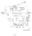
- Fig. 1 is a schematic diagram of the tape tension adjustment system, according to an embodiment the invention.
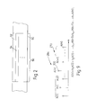
- Fig. 2 is a segment of the tape depicting a multiple track scratch area.
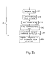
- Fig. 3 is a flow chart of the tape tension optimization procedure.
- Fig. 4 is a history of the test signal written to the tape during tape tension optimization.
- Fig. 5 is tape tension signal history for operating tape tension determination.
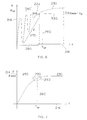
- Fig. 6 is a readback signal amplitude versus tape tension plot in response to a tape tension signal containing a disturbance of pre-determined frequency.
- Fig. 7 is an ideal readback signal amplitude versus tape tension plot in response to tape tension signal.
- Fig. 8 is a magnitude frequency response plot of an ideal low pass filter and its least squares approximation.
- Fig. 9 is a band passed graph of the readback signal amplitude versus the tape tension.
- a tape drive 10 which includes, inter alia, a read/write head 20 provided with a read transducer 30, a forward write transducer 40, and a backward write transducer 42, the write transducers being disposed substantially symmetrically on either side of read transducer 30.
- forward write transducer 40 is located anterior to read head 30 in order to make the data magnetically encoded on the surface of a tape 50 instantly available for reading when tape 50 is advanced in the forward direction.
- backward write transducer 42 posterior to read transducer 30 is similarly intended to accommodate the simultaneous write and read operation when tape 50 is moved in the opposite direction.
- the read and write transducers are spatially disposed on read/write head 20 along a convex surface which is offset from a straight line between the drive rollers of a first or advance motor 60 and a second or trailing motor 70 whereby tape 50 is subjected to tension by being compelled to follow the contour of read/write head 20. If the tape tension is kept constant over many operation cycles, gradual wear of read/write head 20 will eventually result in inadequate head to tape contact and detrimentally affect the readback signal amplitude.
- the purpose of the invention is to adapt the tape tension to the changing physical characteristics of the read/write head.
- the data is written onto tape 50 in accordance with a pre-specified format as tape 50 is moved past read/write head 20 by means of a motor pair consisting of an advance motor 60 and a trailing motor 70.
- a first output terminal of a drive servo system 120 is coupled to an input terminal of advance motor 60 via line 72 to supply a current command I a .
- a second output terminal of drive servo system 120 is coupled to an input terminal of trailing motor 70 via line 74 to supply a current command I t .
- Block 162 in Fig. 1 is a test signal generator whose output terminal is coupled to an input terminal of read/write head 20 via line 164.
- An output terminal of read/write head 20 is coupled to an input terminal of an analog to digital converter 180 (designated A/D) via line 174.
- A/D 180 is used to sample, hold, and digitize an analog test readback signal R t from read transducer 30.
- the test amplitude samples TA i at the output terminal of A/D 180 on line 186 are stored as readback amplitude values A i in a table 202 located inside a memory 200.
- a finite impulse response filter contained in block 310 (designated FIR) interacts with memory 200 via line 188 to further process the readback amplitude values A i stored in table 202 and write them back into the memory as described below in greater detail.
- Block 314 is a control device whose first output terminal is coupled to a second input terminal of memory 200 via line 500, second output terminal is coupled to an input terminal of test signal generator 162 via line 510, third output terminal is coupled to an input terminal of FIR via line 530.
- control device 314 interacts with drive servo system 120 via line 390.
- Control device 314 is responsible for controlling and coordinating the sequence of operations of all the blocks inside a microprocessor 210, delineated by a dashed line in Fig. 1. Although block 314 has been designated a control device, it will be understood that the control functions are effected by microprocessor commands via appropriate hardware and software. The purpose of the various blocks is described in greater detail below.
- the current commands I a and I t are generated by drive servo system 120 of tape drive 10 as a result of computations which are updated at regular intervals and are based upon the desired tape tension, speed, and relevant tape drive parameters. For example, to provide the tape tension sufficient for good head to tape contact and an adequate readback signal amplitude with tape 50 moving in the forward direction, current command I a is produced to acquire and maintain a desired tape speed by imparting an appropriate rotational speed to advance motor 60. At the same time, current command I t supplied to trailing motor 70 is such as to support the desired tape speed as well as induce the necessary tape tension in the segment of tape 50 located between the two motors and in contact with read/write head 20. A test signal appearing on line 164 is supplied to write transducers of read/write head 20 during the tape optimization procedure described in greater detail below.
- the adjustment of tape tension is performed each time a new tape cartridge is loaded into tape drive 10, depicted as step 340 in Fig. 3.
- Tape 50 is positioned at the beginning of a segment designated as a scratch area 56, shown in Fig. 2, which is first erased through the data erasure step 350 with a pre-selected write signal recorded by forward write transducer 40 along a forward track 52 (Fig. 2) on the surface of tape 50 as the tape is moved forward.
- step 360 is initiated whereby read/write head 30 (Fig. 1) is positioned into alignment with a backward track 54 and backward write transducer 42 (Fig. 1) is used to erase the track as tape 50 is moved in the backward direction.
- test signal W t is a current signal of known parameters, such as a fixed frequency and amplitude, applied by test signal generator 162 on line 164 (Fig. 1) to forward write head 40.
- the gain of forward write head 40 is held constant throughout the tape tension optimization procedure.
- control device 314 inside microprocessor 210 transmits a tape tension request TR via line 390 to drive servo system 120 for effecting control of advance motor 60 and trailing motor 70, whereby tape 50 is subjected to a gradual increase in tension.
- the tape tension signal T t is defined by line 190 while the horizontal axis and the vertical axis denote time and tape tension, respectively.
- Drive servo system 120 uses the desired tape tension value T i along with a number of the tape drive parameters as inputs into a periodically repeated sequence of predetermined computations to update the current commands I a and I t supplied to advance motor 60 via line 72 and trailing motor 70 via line 74 accordingly.
- the test readback signal R t appears at the output terminal of read transducer 30 on line 174.
- test readback signal R t is then sampled by A/D 180 to produce the test amplitude samples TA i on line 186.
- the test amplitude samples TA i are next stored as readback amplitude values A i in table 202 inside memory 200. This puts each tape tension value T i and the corresponding readback amplitude value A i of the test readback signal R t into a one-to-one relationship.
- the tape tension signal T t is preferably composed of a ramp R, as depicted by line 170 in Fig. 5, modulated by a periodic test disturbance D t given by line 180, obeying, for example, a sinusoidal law, to emulate tape-read/write head separation condition.
- a periodic test disturbance D t given by line 180
- the test disturbance D t whose frequency content is preferably chosen to coincide with one or more frequencies of the disturbances experienced by tape drive 10 in actual operation, is injected to reproduce the adverse effect of tape-read/write head separation on the tape drive operation.
- step 370 the test readback signal R t is sampled and digitized by A/D 180 (Fig. 1) to generate the test amplitude samples TA i .
- Each readback amplitude value A i and the corresponding desired tape tension value T i forms a pair of values which is then stored in table 202.
- step 372 the tape tension is varied as described in greater detail below.
- step 373 the steps 370 through 372 are repeated until the desired number of the test amplitude samples TA i is collected.
- Each pair of a readback signal amplitude value A i and a corresponding tape tension value T i representing an entry in table 202 may be plotted as shown in Fig. 6.
- the vertical axis 214 denotes the readback signal amplitude A
- the horizontal axis 216 denotes the tape tension T. Relating the tape tension values T i to the actually observed readback amplitude values A i advantageously allows adjustment of the tape tension T to be performed independently of the physical characteristics of the advance and trailing motors 60, 70 in the tape drive 10. This allows tape drive 10 to become less sensitive to physical variations in such characteristics as ambient temperature, humidity, read/write head wear.
- dependency of the readback signal amplitude A on the tape tension T may be expressed in the form of a graph 220 shown in Fig. 7.
- greater tape tension T results in an increase in readback signal amplitude A.
- the rate of growth in the readback signal amplitude A declines eventually approaching zero so that a plateau region given by a line segment 230 is attained. In the plateau region 230 no readback signal amplitude changes occur in response to further tape tension increase.
- a readback amplitude breakdown region 232 may be reached.
- the readback signal amplitude A undergoes a decrease in response to an increase in the tape tension T. This decrease in the readback signal amplitude A may be due to excessive deformation of the tape material or poor head to tape contact due to tape distortion.
- an optimal tape tension T of which best satisfies the two competing objectives with tape 50 moving forward is given by the intersection of line 260 and graph 220 which falls within the region of a knee 240 of graph 220.
- the optimal tape tension T of is selected each time tape 50 (Fig. 1) is loaded to account for head contour variation over time and to preclude overtensioning the tape.
- Fig. 6 depicts a modified embodiment of the invention, in which the tape tension T t contains a test disturbance D t which is intended to induce tape-read/write head separation.
- the resultant readback signal amplitude A exhibits fluctuations F given by the line segment 270 in a low tape tension region defined by the interval 280.
- the fluctuations F in the readback signal amplitude A decay as the tape tension T rises to establish a sufficiently tight contact between tape 50 and read/write head 20 (Fig. 1).
- each readback amplitude value A i is processed through the finite impulse response filter (FIR) 310.
- FIR finite impulse response filter
- FIR 310 The magnitude frequency response of FIR 310 is given by line 318 approximating, for example in a least squares sense, an ideal low pass filter response depicted by line 322 with a desired cutoff frequency f co given by the intersection of lines 314 and 316, as shown in Fig. 8.
- FIR 310 is generally characterized by a finite impulse response which is symmetrical with respect to its central sample as required for a linear phase response. Since the readback amplitude values A i are stored in memory 200 off line, band limiting filtering of the readback amplitude values A i can be performed in a non-causal manner.
- each sample A(k) depicted by line 300, after being processed is in phase with its corresponding tape tension value T k .
- the readback amplitude value A k fil given by the filtered sample A fil (k) is thus stored in the original location in table 202 inside memory 200 during step 375 of the tape tension optimization procedure.
- microprocessor 200 performs step 376 by executing a search through the readback amplitude values A i in table 202 in order to determine a reference value of readback signal amplitude A ref , for example the maximum readback signal amplitude A max .
- a base amplitude value A b given by the intersection of line 330 and graph 222 in Fig. 6, which is equal, for example, to ninety percent of maximum readback signal amplitude A max , is computed by control device 314 (Fig. 1) during the next step 377.
- a backward search through table 202 is performed in step 378 starting with the last readback amplitude value A1 until the maximum readback amplitude value A max is found.
- the search through table 202 then continues until a matching readback amplitude value A m resident in table 202 which is equal to the base amplitude value A b is found. If no such value exists, the nearest readback amplitude value A i is located in table 202, for example the value immediately below or above the base amplitude value A b within a predetermined range.
- the corresponding tape tension value T m in table 202 is located to form a base tape tension value T b .
- a pre-selected offset is added to the base tape tension value T b , for example 3 ounce-force, to compute an operating tape tension value T op which is optimal for tape drive 10.
- the value of the pre-selected offset which is used to obtain the operating tape tension value T op from the base tape tension value T b may be either a positive or a negative value.
- T op is communicated by control device 314 to drive servo system 120 via line 390 in step 381.
- the appropriate schedule of the motor drive current commands I a and I t is computed to realize the operating tape tension T op .
- a search through table 202 is performed to locate the reference amplitude value, such as the maximum readback signal amplitude A max .
- the base amplitude value A b equal to a predetermined percentage of the maximum readback signal amplitude A max , is computed.
- table 202 is searched backwards until the maximum readback signal amplitude A max is found. The search continues until a matching readback amplitude value A m nearest the base amplitude A b is found.
- the corresponding tape tension value T m is located in table 202 to form the base tape tension value T b .
- a pre-selected offset is added to the base tape tension value T b to form the operating tape tension value T op which is implemented in the form of the appropriate current commands I a and I t .
- the tape adjustment procedure of the invention is easily adaptable for use in a multiple read channel tape drive configuration.
- the tape tension calibration is repeated for each group of forward and backward tracks. Since tape to head contact may vary from track to track, a preferred method of tape tension optimization is to select the operating tape tension value in each direction of tape motion based on the channel exhibiting the worst tape to head contact properties.
- the readback signal sequence 284 is additionally processed by a band pass digital filter in order to isolate the dependency of the readback signal amplitude A on the tape tension T within the frequency range of the test disturbance D t thereby facilitating the selection of the optimal tape tension T o for acceptably low fluctuation in the readback signal amplitude A.
- a band pass digital filter Such information, depicted by line 350 in Fig. 9, is stored in a separate table in memory 200 and is used in conjunction with table 202 to determine the optimal tape tension T o .
- the tape tension adjustment procedure detailed in the preferred embodiment is performed while tape drive 10 is in operation following the receipt of a calibration command issued by control device 314 whenever a quality indicator of the readback signal, such as its signal to noise ratio, becomes unacceptable.
- a different tape tension may be required, for example, if the ambient conditions change while the tape data transfer operation is in progress. If the data error rates become excessively high, data transfer operation may be temporarily halted and the tape tension readjusted to the required level.
- the tape tension adjustment in accordance with the invention, advantageously permits the use of the same tape drive in conjunction with a variety of tape cartridges requiring different tensioning for proper data transfer operation because the optimal tape tension value is determined individually for each tape.
Applications Claiming Priority (2)
| Application Number | Priority Date | Filing Date | Title |
|---|---|---|---|
| US692107 | 1991-04-26 | ||
| US07/692,107 US5216556A (en) | 1991-04-26 | 1991-04-26 | Method for optimized tape tension adjustment for a tape drive |
Publications (2)
| Publication Number | Publication Date |
|---|---|
| EP0514007A2 true EP0514007A2 (fr) | 1992-11-19 |
| EP0514007A3 EP0514007A3 (fr) | 1994-03-02 |
Family
ID=24779291
Family Applications (1)
| Application Number | Title | Priority Date | Filing Date |
|---|---|---|---|
| EP92303354A Withdrawn EP0514007A2 (fr) | 1991-04-26 | 1992-04-14 | Méthode de réglage de tension de bande optimale dans un dispositif d'entraînement de bande |
Country Status (4)
| Country | Link |
|---|---|
| US (1) | US5216556A (fr) |
| EP (1) | EP0514007A2 (fr) |
| JP (1) | JP2765779B2 (fr) |
| CA (1) | CA2067024A1 (fr) |
Families Citing this family (19)
| Publication number | Priority date | Publication date | Assignee | Title |
|---|---|---|---|---|
| JP2651639B2 (ja) * | 1992-02-18 | 1997-09-10 | 富士写真フイルム株式会社 | テープ巻取装置 |
| US5566033A (en) * | 1992-08-31 | 1996-10-15 | Frame; Gary E. | Method and apparatus for determining the location of information on a magnetic tape |
| US5572378A (en) * | 1994-06-13 | 1996-11-05 | Imation Corp. | Direct file access system for magnetic tape |
| US5608584A (en) * | 1995-05-25 | 1997-03-04 | Quantum Corporation | Recognition of tape recording media type using plural in-line holes |
| JP3229204B2 (ja) * | 1996-01-26 | 2001-11-19 | シャープ株式会社 | 制御装置および情報記録再生装置 |
| US5886845A (en) * | 1996-08-13 | 1999-03-23 | Imation Corp. | Tape pack shift detection and retensioning methods and drive apparatus regarding same |
| US6241171B1 (en) | 1998-03-26 | 2001-06-05 | Quantum Corporation | Leaderless tape drive |
| US6574679B1 (en) | 1999-07-26 | 2003-06-03 | International Business Machines Corporation | Method and apparatus for identifying hardware |
| US6934108B2 (en) * | 2003-01-22 | 2005-08-23 | International Business Machines Corporation | Servo pattern based tape tension control for tape drives |
| ATE381076T1 (de) * | 2003-08-29 | 2007-12-15 | Thomson Licensing | Verfahren und vorrichtung zur modellierung von filmkorn-mustern im frequenzbereich |
| KR101096916B1 (ko) * | 2004-10-18 | 2011-12-22 | 톰슨 라이센싱 | 필름 그레인 시뮬레이션 방법 |
| JP4960877B2 (ja) * | 2004-11-12 | 2012-06-27 | トムソン ライセンシング | 映像再生システムの通常再生及びトリックモード再生に関するフィルムグレインシミュレーション |
| KR101229942B1 (ko) | 2004-11-16 | 2013-02-06 | 톰슨 라이센싱 | 비디오 시스템에서 비트까지 정확한 시뮬레이션을 위한필름 그레인 sei 메시지 삽입 |
| ATE553455T1 (de) | 2004-11-16 | 2012-04-15 | Thomson Licensing | Verfahren zum simulieren von filmkörnigkeit auf der basis vorausberechneter transformationskoeffizienten |
| TR201911138T4 (tr) | 2004-11-17 | 2019-08-21 | Interdigital Vc Holdings Inc | Ön-hesaplanmış dönüştürülmüş katsayılara dayanan bit bakımından hatasız film greni simülasyon yöntemi. |
| EP1817915A2 (fr) * | 2004-11-22 | 2007-08-15 | THOMSON Licensing | Procedes, appareil et systeme de repartition de cache de grain de film pour simulation de grain de film |
| US10715834B2 (en) | 2007-05-10 | 2020-07-14 | Interdigital Vc Holdings, Inc. | Film grain simulation based on pre-computed transform coefficients |
| US10347282B2 (en) * | 2017-06-23 | 2019-07-09 | International Business Machines Corporation | Tape transport control with suppression of time-varying tension disturbances |
| US11741993B2 (en) * | 2021-09-04 | 2023-08-29 | Quantum Corporation | Method of total dimensional stability control in magnetic tape system with global calibration data |
Citations (2)
| Publication number | Priority date | Publication date | Assignee | Title |
|---|---|---|---|---|
| US3733529A (en) * | 1972-05-22 | 1973-05-15 | Ross Controls Corp | Plural motor tape drive speed control |
| JPH01317255A (ja) * | 1988-06-17 | 1989-12-21 | Hitachi Denshi Ltd | 磁気記録再生装置 |
Family Cites Families (14)
| Publication number | Priority date | Publication date | Assignee | Title |
|---|---|---|---|---|
| US3947880A (en) * | 1961-05-02 | 1976-03-30 | U.S. Philips Corporation | Magnetic recording and reproducing apparatus with tape tension control |
| US3633187A (en) * | 1969-07-25 | 1972-01-04 | Memorex Corp | Method and apparatus for certifying magnetic recording tape |
| US3781490A (en) * | 1973-06-01 | 1973-12-25 | Ibm | Web tension and speed control in a reel-to-reel web transport |
| US4389600A (en) * | 1981-10-26 | 1983-06-21 | International Business Machines Corporation | Tape media interlayer tension check |
| JPS5888851A (ja) * | 1981-11-21 | 1983-05-27 | Matsushita Electric Ind Co Ltd | 磁気記録再生装置 |
| US4413288A (en) * | 1981-12-07 | 1983-11-01 | Rca Corporation | Indicator control signal generator for video tape recorder |
| JPS5930186A (ja) * | 1982-08-06 | 1984-02-17 | インタ−ナシヨナル ビジネス マシ−ンズ コ−ポレ−シヨン | 自動預金・支払装置用紙幣収納機構 |
| US4656530A (en) * | 1985-11-25 | 1987-04-07 | American Multimedia, Inc. | Method and apparatus for servo-control of tape tension in high speed tape transporter |
| JPS62267955A (ja) * | 1986-05-15 | 1987-11-20 | Sony Corp | 記録再生装置 |
| US4807107A (en) * | 1987-08-25 | 1989-02-21 | Ampex Corporation | Apparatus for providing a profiled tape tension without utilizing a tape pack diameter sensor |
| JP2708101B2 (ja) * | 1987-09-25 | 1998-02-04 | 株式会社日立製作所 | テープテンションの制御方法 |
| US5032936A (en) * | 1988-06-27 | 1991-07-16 | Matsusita Electric Industrial Co. Ltd. | Tape tension apparatus |
| JPH02206053A (ja) * | 1989-02-02 | 1990-08-15 | Sharp Corp | 磁気記録再生装置 |
| JP2936606B2 (ja) * | 1989-12-18 | 1999-08-23 | ソニー株式会社 | フリクションキャプスタン駆動方式のテープ走行駆動装置 |
-
1991
- 1991-04-26 US US07/692,107 patent/US5216556A/en not_active Expired - Fee Related
-
1992
- 1992-04-14 EP EP92303354A patent/EP0514007A2/fr not_active Withdrawn
- 1992-04-24 JP JP4106711A patent/JP2765779B2/ja not_active Expired - Fee Related
- 1992-04-24 CA CA002067024A patent/CA2067024A1/fr not_active Abandoned
Patent Citations (2)
| Publication number | Priority date | Publication date | Assignee | Title |
|---|---|---|---|---|
| US3733529A (en) * | 1972-05-22 | 1973-05-15 | Ross Controls Corp | Plural motor tape drive speed control |
| JPH01317255A (ja) * | 1988-06-17 | 1989-12-21 | Hitachi Denshi Ltd | 磁気記録再生装置 |
Non-Patent Citations (2)
| Title |
|---|
| IBM TECHNICAL DISCLOSURE BULLETIN. vol. 15, no. 1 , June 1972 , NEW YORK US pages 121 - 122 BEACH ET AL. 'Reel to Reel Tape Transport' * |
| PATENT ABSTRACTS OF JAPAN vol. 14, no. 124 (P-1018)8 March 1990 & JP-A-01 317 255 (HITACHI DENSHI LTD.) 21 December 1989 * |
Also Published As
| Publication number | Publication date |
|---|---|
| EP0514007A3 (fr) | 1994-03-02 |
| JPH05120762A (ja) | 1993-05-18 |
| CA2067024A1 (fr) | 1992-10-27 |
| US5216556A (en) | 1993-06-01 |
| JP2765779B2 (ja) | 1998-06-18 |
Similar Documents
| Publication | Publication Date | Title |
|---|---|---|
| US5216556A (en) | Method for optimized tape tension adjustment for a tape drive | |
| US5570247A (en) | Self servo writing file | |
| KR100305953B1 (ko) | 트랙형태오차의전달을감소시키는방법과서보기록장치 | |
| CA1326902C (fr) | Methode et appareil d'enregistrement de donnees | |
| JP2592202B2 (ja) | Prmlデータ・チャンネルにおける事前補償値を決定する方法及び装置 | |
| US6411461B1 (en) | Data collection system and method for zero acceleration path correction | |
| KR980011021A (ko) | 셀프 서보기록 시스템과 셀프 서보기록 시스템에서의 다수의 트랙 기록 방법 | |
| US6265868B1 (en) | System and method for measuring total track width of a test track in magnetic media | |
| US5455717A (en) | Recording device with temperature-dependent write-current control | |
| US6751046B1 (en) | Writing servo data patterns on a data storage disk to account for repeatable and non-repeatable disturbances and thereby provide concentric data tracks | |
| US6301209B2 (en) | Recording method, recording apparatus, reproducing method and reproducing apparatus | |
| US5963389A (en) | Tape transport system using variable tape speed to achieve constant data speed and advance detection and correction of tracking errors to reduce data loss errors | |
| KR940007784A (ko) | 이득조정반복학습 제어를 이용한 디스크드라이브의 헤드위치제어 장치 및 방법 | |
| US20040141250A1 (en) | Servo pattern based tape tension control for tape drives | |
| US6545834B1 (en) | Method and apparatus for dimensional tape width compensation in a tape drive system | |
| AU630335B2 (en) | Tracking servo control for disc drive | |
| US4363043A (en) | Circuit arrangement for skipping marked portions of a recording tape | |
| US6175465B1 (en) | Head positioning control system for use in a disk storage drive | |
| US5485320A (en) | Method and apparatus for adjusting asymmetric recording signals | |
| KR0134973B1 (ko) | 레코딩 바이어스의 자동 최적화 방법 및 그 방법을 실행하기 위한 장치 | |
| US5353177A (en) | Method and apparatus for positioning a magnetic head unit on a track centerline | |
| US5477399A (en) | Programmable tension control of a variable speed recorder | |
| US7230783B2 (en) | Mitigation of MR read head distortion | |
| US5442496A (en) | Magnetic tape apparatus including a reading head for reading main information and auxiliary information of a reproducing region together with auxiliary information of another region | |
| US6665137B2 (en) | Method for locating data tracks on a tape media |
Legal Events
| Date | Code | Title | Description |
|---|---|---|---|
| PUAI | Public reference made under article 153(3) epc to a published international application that has entered the european phase |
Free format text: ORIGINAL CODE: 0009012 |
|
| AK | Designated contracting states |
Kind code of ref document: A2 Designated state(s): DE FR GB IT |
|
| PUAL | Search report despatched |
Free format text: ORIGINAL CODE: 0009013 |
|
| AK | Designated contracting states |
Kind code of ref document: A3 Designated state(s): DE FR GB IT |
|
| STAA | Information on the status of an ep patent application or granted ep patent |
Free format text: STATUS: THE APPLICATION IS DEEMED TO BE WITHDRAWN |
|
| 18D | Application deemed to be withdrawn |
Effective date: 19941101 |