EP0512787A2 - Automatisches Ausser-Betrieb-Setzen eines Kommunikationsgerätes - Google Patents
Automatisches Ausser-Betrieb-Setzen eines Kommunikationsgerätes Download PDFInfo
- Publication number
- EP0512787A2 EP0512787A2 EP92304024A EP92304024A EP0512787A2 EP 0512787 A2 EP0512787 A2 EP 0512787A2 EP 92304024 A EP92304024 A EP 92304024A EP 92304024 A EP92304024 A EP 92304024A EP 0512787 A2 EP0512787 A2 EP 0512787A2
- Authority
- EP
- European Patent Office
- Prior art keywords
- pager
- communications
- communications device
- signal
- call
- Prior art date
- Legal status (The legal status is an assumption and is not a legal conclusion. Google has not performed a legal analysis and makes no representation as to the accuracy of the status listed.)
- Withdrawn
Links
Images


Classifications
-
- H—ELECTRICITY
- H04—ELECTRIC COMMUNICATION TECHNIQUE
- H04W—WIRELESS COMMUNICATION NETWORKS
- H04W84/00—Network topologies
- H04W84/02—Hierarchically pre-organised networks, e.g. paging networks, cellular networks, WLAN [Wireless Local Area Network] or WLL [Wireless Local Loop]
- H04W84/10—Small scale networks; Flat hierarchical networks
- H04W84/16—WPBX [Wireless Private Branch Exchange]
-
- H—ELECTRICITY
- H04—ELECTRIC COMMUNICATION TECHNIQUE
- H04M—TELEPHONIC COMMUNICATION
- H04M11/00—Telephonic communication systems specially adapted for combination with other electrical systems
- H04M11/02—Telephonic communication systems specially adapted for combination with other electrical systems with bell or annunciator systems
- H04M11/022—Paging systems
-
- H—ELECTRICITY
- H04—ELECTRIC COMMUNICATION TECHNIQUE
- H04M—TELEPHONIC COMMUNICATION
- H04M3/00—Automatic or semi-automatic exchanges
- H04M3/42—Systems providing special services or facilities to subscribers
- H04M3/42229—Personal communication services, i.e. services related to one subscriber independent of his terminal and/or location
-
- H—ELECTRICITY
- H04—ELECTRIC COMMUNICATION TECHNIQUE
- H04M—TELEPHONIC COMMUNICATION
- H04M2203/00—Aspects of automatic or semi-automatic exchanges
- H04M2203/10—Aspects of automatic or semi-automatic exchanges related to the purpose or context of the telephonic communication
- H04M2203/1091—Fixed mobile conversion
-
- H—ELECTRICITY
- H04—ELECTRIC COMMUNICATION TECHNIQUE
- H04M—TELEPHONIC COMMUNICATION
- H04M2207/00—Type of exchange or network, i.e. telephonic medium, in which the telephonic communication takes place
- H04M2207/18—Type of exchange or network, i.e. telephonic medium, in which the telephonic communication takes place wireless networks
-
- H—ELECTRICITY
- H04—ELECTRIC COMMUNICATION TECHNIQUE
- H04M—TELEPHONIC COMMUNICATION
- H04M2207/00—Type of exchange or network, i.e. telephonic medium, in which the telephonic communication takes place
- H04M2207/20—Type of exchange or network, i.e. telephonic medium, in which the telephonic communication takes place hybrid systems
-
- H—ELECTRICITY
- H04—ELECTRIC COMMUNICATION TECHNIQUE
- H04M—TELEPHONIC COMMUNICATION
- H04M2242/00—Special services or facilities
- H04M2242/30—Determination of the location of a subscriber
-
- H—ELECTRICITY
- H04—ELECTRIC COMMUNICATION TECHNIQUE
- H04M—TELEPHONIC COMMUNICATION
- H04M3/00—Automatic or semi-automatic exchanges
- H04M3/42—Systems providing special services or facilities to subscribers
- H04M3/50—Centralised arrangements for answering calls; Centralised arrangements for recording messages for absent or busy subscribers ; Centralised arrangements for recording messages
- H04M3/53—Centralised arrangements for recording incoming messages, i.e. mailbox systems
- H04M3/533—Voice mail systems
-
- H—ELECTRICITY
- H04—ELECTRIC COMMUNICATION TECHNIQUE
- H04M—TELEPHONIC COMMUNICATION
- H04M7/00—Arrangements for interconnection between switching centres
- H04M7/12—Arrangements for interconnection between switching centres for working between exchanges having different types of switching equipment, e.g. power-driven and step by step or decimal and non-decimal
Definitions
- the present invention relates to communications systems and, more particularly, to a technique for automatically disabling the alerting capability of one communications device when it is within a predetermined distance of another associated communications device.
- Wired communications devices are those which require a signal-conducting path, other than air, between the communications device and a communications system, such as a central office switch or private branch exchange (PBX).
- the signal-conducting path can take many physical forms, including a number of different kinds of metallic conductors or optical fibers.
- wireless communications devices such as paging and cellular radio communications devices, utilize the air as the medium to transport signals to and from the communications system.
- Paging devices are portable one-way communications devices which respond to an associated radio signal which is broadcasted while cellular radio devices provide full two-way communications capabilities.
- the reception of a predetermined radio signal typically activates an audible and/or visual alarm to indicate that the person carrying the pager should make to call a predetermined telephone number to receive a message.
- the paging device may have the capability to receive an incoming message which can be displayed. This message communicates a predefined amount of information which may be the telephone number of a calling party.
- cellular radio devices give rise to a set of other problems.
- One such problem is that cellular telephones are expensive and this expense is not merely that of the portable communications device but also that of the necessary transceivers which must be disposed to provide substantially uniform communications coverage within a given environment.
- the requirements of apparatus associated with two-way cellular radio devices are considerably more sophisticated than those associated with paging devices as the latter apparatus must provide intelligible two-way communications.
- Another problem is that the requirements for cellular two-way radio devices may be difficult if not impossible to achieve in certain noisy environments.
- Still another problem is that the required radio spectrum to provide cellular radio communications may not be available in certain environments or geographical areas.
- the called party must remember to either turn off the pager when in close proximity to his or her other associated wired or wireless communications device and then later reactivate the pager when at locations remote from such associated communications devices or to manually turn off the pager alarm mechanism in response to each incoming call. Either of these requirements is an annoyance to many pager users, and it would be extremely desirable if a better solution could be devised.
- the present invention relates to a communications system wherein a called party is associated with a plurality of communications devices.
- the alerting capability e.g., the audible and/or visible signalling apparatus
- the audible and/or visible signalling apparatus of one communications device associated with a called party is disabled when it is within a predetermined distance of another communications device associated with that called party.
- this predetermined distance can be varied to suit different applications.
- the aforesaid concept is applied to the situation where a called party is associated with a pager and a wired or wireless two-way communications device.
- the alerting capability of either the pager or the other associated communications device is disabled when these two devices are within a predetermined distance of one another.
- FIG. 1 shows an exemplary application of the present invention wherein PBX 100, for example, an AT&T Definity® telecommunications system has its "trunk” side connected to a plurality of trunks 101-1 through 101-N via trunk interface circuits 111 and its "line” side connected to a plurality of wired communications devices 102-1 through 102-P and wireless communications devices 112-1 through 112-Q via line interface circuits 122 and 123, respectively.
- the trunks connect to an external communications network (not shown) which may be either a public or private network.
- Each of the variables P and Q is a predetermined integer and since a PBX may be designed to be blocking or nonblocking, the number of trunks, N, is less than or equal to the total number of wired and wireless communications devices, P+Q.
- a plurality of pagers 122-1 through 122-R and a plurality of voice mail systems 132-1 through 132-S are also connected to the line side of PBX 100 via line interface circuits 124 and 125, respectively.
- Each voice mail system has the capability of providing voice announcements to calling parties in certain circumstances, such as when the called party does not answer.
- the mix of wired and wireless communications devices, pagers and voice mail systems is arbitrary so that the integers P, Q, R and S can each vary to suit different applications.
- the wired or wireless communications devices provide full two-way voice communications capabilities
- such devices can also provide a myriad of other communications functions and may include personal computers, video terminals, environmental sensing devices, such as smoke detectors, facsimile machines, etc.
- the connection between each port on line interface circuits 122 and 125 to its associated wired communications device and voice mail system is respectively provided by one of wired communications links 126 and 129.
- the connection between each port on line interface circuits 123 and 124 to its associated wireless communications device and pager is respectively provided by one of the wireless communications links 127 and 128.
- Each pager provides signal receiving capability and, pursuant to one aspect of the present invention, is associated with a respective one of the wired or wireless communications devices such that an incoming call to such a wired or wireless communications device will also automatically alert the pager.
- this automatic alerting capability can be automatically disabled when the pager and associated wired or wireless communications device are in close proximity to one another.
- a pager is provided with limited transmission capability wherein a called party who is away from his associated wired or wireless communications device can signal call processor 109 within control complex 105 of an intent to respond to the call. Having such an intent, the called party can go to any of the wired or wireless communications devices 102-1 through 102-P or 112-1 through 112-Q and signal the communications system. In response to this signal, the call processor will ultimately direct the incoming call to the wired or wireless communications device from which the called party signalled.
- Each of the wired and wireless communications devices is connected to a "port" of an associated one of line interface circuits 122 and 123, respectively.
- each of the paging transceivers and voice mail systems is respectively connected to a port on an associated one of line interface circuits 124 and 125.
- each line interface circuit has a plurality of ports so that the total number of line interface circuits is less than the total number of wired and wireless communications devices, pagers and voice mail systems, i.e., P+Q+R+S.
- PBX 100 provides a communications system switching interface for incoming, outgoing and internal communications.
- "Incoming” communications are those which originate within the external communications network and are destined for at least one of the wired or wireless communications devices.
- "Outgoing” communications are those which originate from one of these communications devices and are destined for some other communications device within the external communications network (both of the latter not shown).
- "internal” communications are those which originate from one of the communications devices and terminate on a different one of these communications devices.
- PBX 100 can be one PBX in a network of interconnected PBXs and, in such situations, internal communications can also originate from and terminate on communications devices in different PBXs in the network of PBXs.
- the present invention addresses problems that arise in internal communications when the called party is associated with both a pager and a wired or wireless communications device possessing full two-way communications capabilities.
- a calling party must dial two different telephone numbers or PBX extensions wherein one number is associated with the wired or wireless communications device and the other is associated with the paging device.
- the present invention overcomes this problem by providing communications access to both such devices via a single telephone number or PBX extension. Before describing how this is accomplished, it is first necessary to briefly review the call processing capability of the PBX for incoming communications.
- signalling information has to be coupled to the destined communications device.
- This coupling of signalling information is through the control complex 105 but the voice/data communications which follow this signalling transfer is not coupled to the control complex, but rather is transferred directly between the trunk interface and line interface circuit by time-division-multiplexed TDM) bus 106.
- TDM time-division-multiplexed bus 106.
- Signalling for incoming communications, received via a trunk and its associated trunk interface circuit, are routed to control complex 105 via the TDM bus.
- this signalling is serially coupled through processor interface 107 and M-bus 108 to call processor 109.
- Processor 109 utilizing software stored in program memory 110 and specific system information stored in translation memory 111 and status memory 112, processes the received dialed digits for the incoming communications to provide signalling to the destined communications device via its associated line interface circuit and communications link.
- This connection to the associated line interface circuit is provided via M-bus 108, processor interface 107 and TDM bus 106.
- the incoming signalling is routed to the port connected to the communications link extending to the destined communications device.
- signalling for outgoing communications is outputted to the associated communications link and line interface circuit and then is routed to the control complex via the TDM bus.
- the signalling for outgoing communications is serially routed through processor interface 107, M-bus 108 and call processor 109.
- the dialed digits are analyzed utilizing software within program memory 110, specific system information stored in the translation and status memories and a signalling interconnection is provided to one of the trunks and its associated trunk interface circuit in accordance with a predetermined routing scheme.
- This interconnection is provided via the M-bus, processor interface and TDM bus.
- Internal communications between at least two wired or wireless communications devices are processed in much the same fashion as just described with the call processor determining the associated line interface circuit associated with the destined communications device.
- the signalling connection to and from the call processor is provided via the TDM bus, processor interface and M-bus.
- the call processor routes the signalling to a preselected trunk and trunk interface circuit via the M-bus, processor interface and TDM bus.
- communications services are provided as if the communications originated within that PBX.
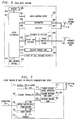
- FIG. 2 shows the information in translation memory 111 utilized pursuant to the present invention.
- the first item in the translation memory is the extension number 201. This number is used to identify both the wired or wireless communications device along with any pager associated with this extension number.
- the pager digital code 202 is the digital code word to which the pager associated with extension number 201 is responsive. A given pager will be responsive to only one digital code 202 which is transmitted by a paging transceiver in communications system 100.
- the line interface circuit (LIC) number 203 and the port 204 on this LIC are used to identify the physical location of the communication system port interfacing the wired or wireless communications device.
- Name 205 is used to identify the user's name normally associated with extension number 201.
- the communications device type 206 is used to identify the type of communications device associated with extension number 201, so that the proper signaling sequence for this communications device can be implemented.
- the pager type 207 is used to identify the type of pager so that the proper signaling sequence for this pager can be implemented.
- the pager code word 208 is used, for security purposes, to verify that the proper pager is responding to any page. This pager code word is automatically transmitted by the pager whenever it transmits signals to communications system 100.
- the priority number list 209 is a list of extensions or users' names to which the pager will respond when the "priority page" feature, as will be subsequently described, is activated.
- call coverage extension 210 identifies the telephone number or extension of the communications device to which calls directed to extension number 201 are forwarded when call coverage, a well-known feature in communications systems, is activated.
- FIG. 3 shows the information in status memory 112 needed to implement the present invention.
- Extension number 301 is analogous to extension number 201 of FIG. 2.
- the remainder of the status memory information is divided into three tables--the call status table 302, the feature status table 301, and the pager status table 307.
- Call status table 302 sets forth a list of entries which indicate whether any one of a predetermined integer number, N, of simultaneously receivable calls for an extension number is active or inactive at any given time. These entries are designated as 303-1 through 303-N.
- Feature status table 304 includes entries 305 and 306 which respectively indicate whether the send all calls and priority page features are active or inactive for an extension number.
- Pager status table 307 includes two entries with the first entry 308 indicating whether the pager associated with extension 301 is active or inactive and the second entry 309 indicating whether the pager is within a predetermined distance of its associated wired or wireless communications device. Entry 309 is used, as will be described, to enable or disable a pager's audible alerting mechanism in response to a page. Specifically, pursuant to the present invention, this alerting mechanism is deactivated when the pager is within a predetermined distance of its associated communications device because an audible alert in such a situation is unnecessary and irritating to system users.
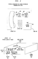
- the physical arrangement of an exemplary wired or wireless communications device is shown in FIG. 4.
- the communications device has several lamps and buttons in addition to the base 408, the key pad 407, and the handset 406.
- the send all calls button 402 is used to activate the send all calls feature which, as is well known, directs all calls from a communications device to a call coverage communications device and, in accordance with the present invention, can selectively direct all calls to any pager associated with a communications device.
- the send all calls lamp 401 is used to alert the user of the communications device that the call coverage feature is active, as such feature activation suspends ringing of the communications device in response to an incoming call.
- the priority page button 401 is used to signal communication system 100 to alert a pager associated with the wired or wireless communications device only when such communications device is called by one of a predesignated list of calling party telephone numbers, extensions or alphanumeric identifiers, collectively set forth in priority number list 209 in FIG. 2.
- Priority page lamp 403 indicates whether this feature is active.
- the message waiting lamp 405 alerts the user of a retrievable message, e.g., a voice mail message. Lamp 405 is typically controlled by a communications system to be on when there is a message waiting and be off when either there are no messages to be retrieved or when all such messages have already been retrieved.
- the priority page button may advantageously be disposed only on a pager or may be replicated on both the wired or wireless communications device and its associated pager.
- FIG. 5 shows a typical pager device physical layout pursuant to the present invention.
- Paging device 501 includes an alphanumeric display 506 capable of displaying both the number associated with a calling party as well as the name or other identifying information of such a party.
- Paging device 501 also includes a message waiting lamp 504. In lieu of such a lamp, the function of the message waiting lamp can be provided by an icon which is selectively activated or illuminated on display 506. The user is alerted to a new incoming call by one or more audible tones emitted by audio alerting device 505.
- Such bridging can be provided to the wired or wireless communications device normally associated with the pager user or can be any wired or wireless communications device connected to the communications system Moreover, the wireless communications device may encompass a well-known "telepoint" device location, i.e., a location where a base transceiver is disposed for public use, and which transceiver is designed to communicate with a user's wireless telephone device.
- Activation of the send to call coverage feature indicates that the pager user does not wish to answer the incoming call and that the predefined call coverage communications device should be alerted.
- This call coverage communications device can be any of the other wired or wireless communications devices connected to system 100.
- an incoming call is directed to the call coverage communications device when a pager user does not activate the will answer or send to call coverage feature after a predetermined time interval has elapsed from the time the pager has been alerted.
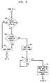
- FIG. 6 shows the pager block diagram.
- Pager controller 617 receives information from communication system 100 via pager antenna 619, lead 618 and receiver 607 and transmits information to such communications system via this antenna 619, lead 618 and transmitter 605.
- a single pager antenna 619 is used and such use is typical of pagers wherein the transmit and receive radio frequencies are the same or closely spaced. If substantially different transmit and receive frequencies are used, then separate receive and transmit antennas can be employed.
- Pager controller 617 is connected to display 506 by conductor 602.
- Conductor 602 couples calling party number and/or other alphanumeric information to the display.
- the proximity antenna 620 is used to receive continuously or periodically transmitted, low-power, radio frequency (RF) signals from the associated wired or wireless communications device which are then coupled to proximity RF receiver 609 via conductor 621.
- RF radio frequency
- Such signals can be a variety of types other than radio, such as infrared or ultrasonic signals. For the latter two types of signals, antenna 620 would be replaced by an appropriate transducer.
- Proximity receiver 609 compares the amplitude of the signal received by the proximity antenna to a predetermined value to determine if the pager is within a predetermined distance of its associated wired or wireless communications device. The results of this determination are coupled via conductor 610 to the pager controller which selectively activates the audio alerting device. Specifically, as will be described in further detail hereinbelow, when the pager is within a predetermined distance of its associated wired or wireless communications device, the pager controller does not activate the audio alerting device. The will answer button 502 and the send to call coverage button 503 are respectively connected to pager controller 617 by conductors 616 and 614. Similarly, the pager controller, in response to a message waiting for the associated wired or wireless communications device, activates message waiting lamp 611 via conductor 612.
- connection 701 connects digital multiplexer/demultiplexer 702 to the associated LIC port.
- connection 701 to the associated LIC is a wired one
- connection 701 is a wireless one to the wireless communications device transceiver and thence is a wired connection to the associated LIC port.
- Digital multiplexer/demultiplexer 702 separates voice or data from the signaling information.
- Voice information coupled from the associated line interface circuit port is provided to audio circuit 710 via conductor 709. Within the audio circuit, the voice information is amplified and processed and thence coupled through conductor 711 to handset 712. In similar fashion, audio information received by the microphone (not shown) within handset 712 is also coupled by conductor 711 to audio circuit 710.
- Feature controller 703 receives signaling information from digital multiplexer/demultiplexer 702 via conductor 704.
- the handset switch hook 715 couples information to feature controller 703 as to whether the handset is on-hook or off-hook via conductor 716.
- Feature controller 703 also receives information through conductor 706 from the feature buttons 402 and 404 and lamps 401, 403 and 405 of FIG. 4.
- Message waiting lamp 405 is activated or deactivated by feature controller 703 using signals coupled through conductor 708.
- Low-power pager locator signal generator 713 outputs a continuous, low-power signal to antenna 714 which is used by the pager to deactivate its audio alerting device 505 when the pager and the associated wired or wireless communications device are within a predetermined distance of one another.
- Pager locator signal generator 713, proximity receiver 609 and pager controller 617 function together to selectively disable the operation of audio alerting device 505 when the pager is within a predetermined distance of its associated wired or wireless communications device.
- this disablement does not occur.
- a different digital code is assigned to each pager and its associated wired or wireless communications device and is used to identify a pager to such a device.
- the code word is generated within the wired or wireless communications device by feature controller 703 and coupled therefrom via conductor 717 to pager locator signal generator 713.
- Generator 713 generates digitally encoded continuous or periodic radio frequency signals containing the digital code and passes these signals to antenna 714. These signals are received by a pager via proximity antenna 620 and coupled to power threshold device 623. Device 623 determines if the received signal generated by pager locator signal generator 713 is above a predetermined power level which corresponds to the typical power level when a pager is within the predetermined distance of its associated wired or wireless communications device. If the received signal level is less than the predetermined power level, then no action is taken.
- the received signal is coupled from the power threshold device to digital code matcher 624 which determines if the received signal contains the digital code matching that of the pager and, therefore, indicating that the received signal emanated from the associated wired or wireless communications device. If the digital code word in the received signal matches that of the pager, then a signal is coupled to pager controller 617 via conductor 610 which causes the controller to send a signal through conductor 604 which disables the operation of audio alerting device 505.
- the threshold utilized by device 623 could be adjustable and such adjustment could be made manually by the pager user or could be done remotely using a signalling protocol received by pager controller 617 and coupled to power threshold device 623.
- call processor 109 of FIG. 1 in response to an incoming call with the sequence of call processor operations beginning at start connector 801 of FIG. 8.
- call processor 109 locates the information in translation memory 111 and status memory 112 associated with the called number or extension.
- data entry 305 in the feature status table is examined to determine whether the send all calls feature is activated. If so, at step 816 the call is sent to call coverage. From step 816, the sequence of call processing operations next proceeds to step 816 where in the existence of call coverage extension data, designated as data entry 210 in FIG.
- call processor 109 determines whether or not the call coverage extension data exists, then it is assumed that the called number or extension does not have call coverage. If, however, there is call coverage extension data, then call processor 109 will direct the application of a ringing signal to this call coverage communications device for a predetermined number of rings. If there is no call coverage extension data or if the call coverage communications device is not answered after the predetermined number of rings, then call processor 109 proceeds to step 818 wherein the call is sent to voice mail. If there is call coverage extension data and the call coverage communications device responds within the predetermined number of rings, then call processing proceeds to step 820 wherein the person answering the call at the call coverage communications device decides at step 822 whether or not the pager associated with the called party should be activated.
- call processing proceeds to step 824 wherein the call is sent to voice mail. Finally, if the person at the call coverage communications device decides it appropriate to alert the pager associated with the called party, then call processing proceeds to step 824 wherein this pager is alerted and processing proceeds on to connector E.
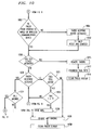
- step 1009 a decision is made relative to whether a response has been received from the alerted pager.
- a pager response is considered received when the pager codeword, designated as item 208 in FIG. 2, is received by the communications system within a predetermined amount of time. If no such pager response is received, call processing continues to step 1021 which determines if the call is still active. If so, processing proceeds to step 1023 which determines whether or not a preselected time interval has elapsed since the time the pager was alerted. This time interval is designated as T1.
- step 1024 If the elapsed time interval is less than T1, call processing continues via path 1024 back to step 1009 and this step, along with steps 1021 and 1023, are repeated until either a pager response is received, the call becomes inactive or time interval T1 has elapsed. Once time interval T1 has elapsed, call processing proceeds to step 1026 where the call is sent to a voice mail system and then ringing is removed from the wired communications device and the pager display is cleared as respectively shown by steps 1028 and 1030.
- step 1011 which asks if the called party has indicated his/her intent to answer the page by depressing the "will answer" button on the pager device. If the will answer button has been activated within a predetermined amount of time, then it is assumed that the called party is en route to a wired or wireless communications device and call processing proceeds to connector H. Before examining the operations subsequent to connector H, let us consider the sequence of operations where the called party has not depressed the will answer button and, therefore, a pager response has not been received. The call processor now assumes that the send to coverage button has been depressed and at step 1026 the call is forwarded to the voice mail system.
- step 1021 determines that the call is not active. Such a determination is made by looking at the appropriate status memory information, designated as 303-1 through 303-N in FIG. 3. If the call is not active, then, at step 1028, ringing of the communications device is terminated and, at step 1030, the pager display is cleared.
- step 1011 determines if the called party has indicated his/her intent to answer the call within a predetermined time interval by pressing the will answer button.
- Call processing now proceeds from connector H to step 1102 of FIG. 11 where the call is "parked" for further processing.
- the term parked means that the call is held, i.e., not terminated, pending a decision as to whether the will answer or send to coverage button has been depressed or whether a predetermined time interval T2 has elapsed.
- step 1102 the timer for measuring time interval T2 is reset and then started.
- step 1104 determines if the called party has responded with a preassigned identification from a wired or wireless communications device connected to the communications system.
- Such a preassigned identification can be the extension number 201 normally associated with the called party or a password typically known only to the called party and the communications system. If the preassigned identification has not been received, call processing proceeds to step 1106, and if the time interval T2 has elapsed, call processing continues on to step 1110. At step 1110, the calling party receives a prerecorded voice message that the called party was unable to find a wired or wireless communications device to answer the call and call processing now proceeds to step 1112 wherein the call is sent to a voice mail system and thence to steps 1114 and 1116 wherein ringing is removed from the communications device and then the pager display is clear. If the time interval T2 has not elapsed, then call processing returns to step 1104.
- the parked call is identified using well-known techniques and is connected to the wired or wireless communications device from which the called party has responded with his or her preassigned identification.
- ringing is removed from the communications device associated with the originally called telephone number or extension at step 1114 and the pager display is cleared and processing concluded for this call at step 1116.
- step 805 of FIG. 8 determines if the send all calls feature has been activated.
- step 807 a determination is made as to whether the called party is currently being paged for a previously received call. If this is so, then in order not to confuse the called party by further alerting his or her pager, call processing proceeds to step 828 where a ringing counter is reset and started and thence a ringing signal is applied to the called party's wired or wireless communications device at step 829.
- This ringing is applied, as shown by step 830, for a predetermined number of rings and, once this number has been reached and the call has still not been answered, then, at steps 836 and 837, respectively, the ringing signal to the called party's wired or wireless communications device is terminated and the call is sent to the voice mail system.
- step 807 If the decision at step 807 is no, i.e., it is determined that the present call is the only active call for called party's number or extension, then call processing continues to step 809 which rings the wired or wireless communications device associated with the called party's number or extension and thence goes on to connector A.
- step 902 determines if the priority page only feature has been activated for the called party's wired or wireless communications device. As discussed above, such activation is accomplished by pressing button 404 in FIG. 4. If this feature has not been activated, then the called party's pager is alerted at step 914 and processing continues on to connector C.
- step 904 determines if number or extension of the calling party number is on the priority list for the called party. If so, the pager is alerted at step 914 and processing proceeds to connector C. If the telephone number or extension of the calling party is not on the priority list, then, at step 907, the timer for time interval T3 is reset and started. Processing now advances to step 908 and is parked or remains there until the T3 time interval has elapsed. This allows for the wired or wireless communications device associated with the called party number or extension to ring a predetermined number of times even though the associated pager is not activated.
- step 911 ringing is removed from the wired or wireless communications device and processing proceeds on to connector B and then on to block 812 of FIG. 8 which sends the call to call coverage. At this point, the call processing proceeds as previously described.
- step 1002 which asks if the pager is near, i.e., within a predetermined distance, of its associated wired or wireless communications device. This determination is carried out by proximity receiver 609 of pager block diagram of FIG. 6. If the pager is not near its associated communications device, then the pager's audio alerting device is activated at step 1004, the timer for measuring time interval T1 is reset and started at step 1032 and processing continues on to step 1006. If the pager is near its associated communications device, processing proceeds on to step 1006.
- step 106 If the communications device associated with the called party is not answered, then processing continues on to step 1009 and proceeds as previously described.
- the present invention can be implemented within other communications systems providing switching capability within a telephone central office or within a customer's premises.
- the communications between the pager and associated communications device is a radio signal, other signals, such as infrared or ultrasonic signals can be used.
- the communications device associated with the pager is one providing voice communications, this associated device can also be one which provides data communications and, therefore, can encompass facsimile machines, video terminals, text terminals and personal computers.
- the present invention is applicable to virtually any situation wherein a called party is associated with a plurality of communications devices.
- the alerting capability of one such device is disabled when within a predetermined distance of another such device.
- the alerting mechanism of the pager is disabled when the pager is within a predetermined distance of its associated communications device, alternatively, the pager alerting mechanism could remain active and the alerting mechanism of the associated communications device could be disabled in such circumstances.
- this alteration merely requires that the location of signal generator 713 and priority RF receiver 609 be interchanged so that the proximity RF receiver selectively disables the typical audio and/or visual alerting device in the full two-way wired or wireless communications device.
Landscapes
- Engineering & Computer Science (AREA)
- Signal Processing (AREA)
- Computer Networks & Wireless Communication (AREA)
- Mobile Radio Communication Systems (AREA)
Applications Claiming Priority (2)
| Application Number | Priority Date | Filing Date | Title |
|---|---|---|---|
| US69928791A | 1991-05-10 | 1991-05-10 | |
| US699287 | 1991-05-10 |
Publications (2)
| Publication Number | Publication Date |
|---|---|
| EP0512787A2 true EP0512787A2 (de) | 1992-11-11 |
| EP0512787A3 EP0512787A3 (en) | 1993-07-28 |
Family
ID=24808675
Family Applications (1)
| Application Number | Title | Priority Date | Filing Date |
|---|---|---|---|
| EP19920304024 Withdrawn EP0512787A3 (en) | 1991-05-10 | 1992-05-05 | Automatic communications device disablement |
Country Status (3)
| Country | Link |
|---|---|
| EP (1) | EP0512787A3 (de) |
| JP (1) | JPH05153256A (de) |
| CA (1) | CA2063359A1 (de) |
Cited By (2)
| Publication number | Priority date | Publication date | Assignee | Title |
|---|---|---|---|---|
| WO1994023524A1 (de) * | 1993-04-01 | 1994-10-13 | Helfried Schnallinger | Telefonanlage |
| EP0691777A3 (de) * | 1994-07-06 | 2000-05-31 | Siemens Business Communication Systems, Inc. (a Delaware corp.) | System und Verfahren zur Integration eines Personenrufanbieters in einer Nebenstelleanlageumgebung |
Citations (3)
| Publication number | Priority date | Publication date | Assignee | Title |
|---|---|---|---|---|
| FR2541020A1 (fr) * | 1983-02-16 | 1984-08-17 | Jeumont Schneider | Procede et dispositif de localisation de personnes en vue d'etablir une communication telephonique |
| DE3428355A1 (de) * | 1984-08-01 | 1986-02-13 | Robert Bosch Gmbh, 7000 Stuttgart | Verfahren zum herstellen von nachrichtenverbindungen |
| GB2222503A (en) * | 1988-09-06 | 1990-03-07 | Callscan Limited | Locating apparatus |
Family Cites Families (2)
| Publication number | Priority date | Publication date | Assignee | Title |
|---|---|---|---|---|
| JPS5846106B2 (ja) * | 1978-06-12 | 1983-10-14 | 日本電信電話株式会社 | 発着信制御方式 |
| JPH01194643A (ja) * | 1988-01-29 | 1989-08-04 | Nec Corp | 不在内線ポケットベル呼出方式 |
-
1992
- 1992-03-18 CA CA002063359A patent/CA2063359A1/en not_active Abandoned
- 1992-05-05 EP EP19920304024 patent/EP0512787A3/en not_active Withdrawn
- 1992-05-08 JP JP14203192A patent/JPH05153256A/ja active Pending
Patent Citations (3)
| Publication number | Priority date | Publication date | Assignee | Title |
|---|---|---|---|---|
| FR2541020A1 (fr) * | 1983-02-16 | 1984-08-17 | Jeumont Schneider | Procede et dispositif de localisation de personnes en vue d'etablir une communication telephonique |
| DE3428355A1 (de) * | 1984-08-01 | 1986-02-13 | Robert Bosch Gmbh, 7000 Stuttgart | Verfahren zum herstellen von nachrichtenverbindungen |
| GB2222503A (en) * | 1988-09-06 | 1990-03-07 | Callscan Limited | Locating apparatus |
Cited By (3)
| Publication number | Priority date | Publication date | Assignee | Title |
|---|---|---|---|---|
| WO1994023524A1 (de) * | 1993-04-01 | 1994-10-13 | Helfried Schnallinger | Telefonanlage |
| EP0691777A3 (de) * | 1994-07-06 | 2000-05-31 | Siemens Business Communication Systems, Inc. (a Delaware corp.) | System und Verfahren zur Integration eines Personenrufanbieters in einer Nebenstelleanlageumgebung |
| CN1098603C (zh) * | 1994-07-06 | 2003-01-08 | 西门子罗尔姆通讯公司 | 寻呼服务器组合入专用小交换机环境的系统和方法 |
Also Published As
| Publication number | Publication date |
|---|---|
| EP0512787A3 (en) | 1993-07-28 |
| JPH05153256A (ja) | 1993-06-18 |
| CA2063359A1 (en) | 1992-11-11 |
Similar Documents
| Publication | Publication Date | Title |
|---|---|---|
| US5311570A (en) | Integration of wireless paging in a communication system | |
| US5481590A (en) | Selection of a communication terminal for receiving an incoming call | |
| CA2076434C (en) | Incoming communications forwarding technique utilizing a called party location indicator | |
| EP0647075B1 (de) | System und Verfahren zur Identifizierung der angerufenen Anschlussnummer wenn einem drahtlosen Gerät mehrere Anschlussnummern zugeteilt sind | |
| US4796291A (en) | Mobile radio communications system | |
| JPH06500672A (ja) | 電話送信側と呼出受信側とを接続する電話呼出装置 | |
| JPH0690481A (ja) | 移動端末トラッキング方法及びシステム | |
| EP1044555A1 (de) | Informationsübertragung während anrufherstellung | |
| US5649003A (en) | Method in a communications systems for providing an out-of-band signaling response based on predetermined conditions | |
| US4947420A (en) | Communication system | |
| US6625452B2 (en) | Radio telephone system | |
| GB2298552A (en) | Cordless radio telephone system with a plurality of portable units | |
| EP0512787A2 (de) | Automatisches Ausser-Betrieb-Setzen eines Kommunikationsgerätes | |
| CN1267993A (zh) | 具有监听功能的无绳电话系统 | |
| JP3037257B2 (ja) | Phs電話システム回線を利用した防犯ベル | |
| CN1126394C (zh) | 处理呼入的主叫用户识别消息的多线路电话系统和方法 | |
| JP2612772B2 (ja) | 個人呼出通信システム | |
| JP2722632B2 (ja) | 無線呼出方式 | |
| GB2193061A (en) | Emergency call acceptor | |
| JP2000069124A (ja) | 発呼者番号表示機能付電話機における着信通知方法 | |
| JPH0478255A (ja) | 構内交換機システム | |
| JPH0478256A (ja) | 構内交換機システム | |
| JPH06152746A (ja) | 電話交換装置 | |
| JPH03286661A (ja) | 電話交換装置 | |
| JPH0591043A (ja) | 移動通信システム |
Legal Events
| Date | Code | Title | Description |
|---|---|---|---|
| PUAI | Public reference made under article 153(3) epc to a published international application that has entered the european phase |
Free format text: ORIGINAL CODE: 0009012 |
|
| AK | Designated contracting states |
Kind code of ref document: A2 Designated state(s): DE FR GB SE |
|
| PUAL | Search report despatched |
Free format text: ORIGINAL CODE: 0009013 |
|
| AK | Designated contracting states |
Kind code of ref document: A3 Designated state(s): DE FR GB SE |
|
| 17P | Request for examination filed |
Effective date: 19940112 |
|
| RAP3 | Party data changed (applicant data changed or rights of an application transferred) |
Owner name: AT&T CORP. |
|
| STAA | Information on the status of an ep patent application or granted ep patent |
Free format text: STATUS: THE APPLICATION HAS BEEN WITHDRAWN |
|
| 18W | Application withdrawn |
Withdrawal date: 19950626 |