EP0512288A1 - Filtre à bande pour séparer des impuretés des bains liquides - Google Patents
Filtre à bande pour séparer des impuretés des bains liquides Download PDFInfo
- Publication number
- EP0512288A1 EP0512288A1 EP92106496A EP92106496A EP0512288A1 EP 0512288 A1 EP0512288 A1 EP 0512288A1 EP 92106496 A EP92106496 A EP 92106496A EP 92106496 A EP92106496 A EP 92106496A EP 0512288 A1 EP0512288 A1 EP 0512288A1
- Authority
- EP
- European Patent Office
- Prior art keywords
- belt
- filter according
- band filter
- bath tub
- rollers
- Prior art date
- Legal status (The legal status is an assumption and is not a legal conclusion. Google has not performed a legal analysis and makes no representation as to the accuracy of the status listed.)
- Granted
Links
- 239000007788 liquid Substances 0.000 title claims abstract description 48
- 239000012535 impurity Substances 0.000 title 1
- 239000004744 fabric Substances 0.000 claims abstract description 7
- 239000002245 particle Substances 0.000 claims description 18
- 239000000696 magnetic material Substances 0.000 claims description 7
- 238000007667 floating Methods 0.000 claims description 5
- 230000002093 peripheral effect Effects 0.000 claims description 5
- 238000007790 scraping Methods 0.000 claims description 3
- 230000000284 resting effect Effects 0.000 claims description 2
- 230000001360 synchronised effect Effects 0.000 claims 1
- 238000001914 filtration Methods 0.000 abstract description 3
- 238000013461 design Methods 0.000 description 3
- 239000003921 oil Substances 0.000 description 3
- 238000012549 training Methods 0.000 description 3
- 230000008901 benefit Effects 0.000 description 2
- 230000005540 biological transmission Effects 0.000 description 2
- 238000010586 diagram Methods 0.000 description 2
- 238000000034 method Methods 0.000 description 2
- 230000008569 process Effects 0.000 description 2
- 238000007789 sealing Methods 0.000 description 2
- 230000009471 action Effects 0.000 description 1
- 230000015572 biosynthetic process Effects 0.000 description 1
- 230000008859 change Effects 0.000 description 1
- 239000000356 contaminant Substances 0.000 description 1
- 230000008878 coupling Effects 0.000 description 1
- 238000010168 coupling process Methods 0.000 description 1
- 238000005859 coupling reaction Methods 0.000 description 1
- 238000007599 discharging Methods 0.000 description 1
- 238000006073 displacement reaction Methods 0.000 description 1
- 230000000694 effects Effects 0.000 description 1
- 230000002996 emotional effect Effects 0.000 description 1
- 238000002474 experimental method Methods 0.000 description 1
- 239000012530 fluid Substances 0.000 description 1
- 230000001771 impaired effect Effects 0.000 description 1
- 230000010354 integration Effects 0.000 description 1
- JEIPFZHSYJVQDO-UHFFFAOYSA-N iron(III) oxide Inorganic materials O=[Fe]O[Fe]=O JEIPFZHSYJVQDO-UHFFFAOYSA-N 0.000 description 1
- 230000005415 magnetization Effects 0.000 description 1
- 238000012423 maintenance Methods 0.000 description 1
- 230000002441 reversible effect Effects 0.000 description 1
- 238000000926 separation method Methods 0.000 description 1
- 239000010802 sludge Substances 0.000 description 1
- 230000002195 synergetic effect Effects 0.000 description 1
Images


Classifications
-
- B—PERFORMING OPERATIONS; TRANSPORTING
- B01—PHYSICAL OR CHEMICAL PROCESSES OR APPARATUS IN GENERAL
- B01D—SEPARATION
- B01D33/00—Filters with filtering elements which move during the filtering operation
- B01D33/04—Filters with filtering elements which move during the filtering operation with filtering bands or the like supported on cylinders which are impervious for filtering
-
- B—PERFORMING OPERATIONS; TRANSPORTING
- B01—PHYSICAL OR CHEMICAL PROCESSES OR APPARATUS IN GENERAL
- B01D—SEPARATION
- B01D33/00—Filters with filtering elements which move during the filtering operation
- B01D33/056—Construction of filtering bands or supporting belts, e.g. devices for centering, mounting or sealing the filtering bands or the supporting belts
-
- B—PERFORMING OPERATIONS; TRANSPORTING
- B01—PHYSICAL OR CHEMICAL PROCESSES OR APPARATUS IN GENERAL
- B01D—SEPARATION
- B01D33/00—Filters with filtering elements which move during the filtering operation
- B01D33/44—Regenerating the filter material in the filter
- B01D33/46—Regenerating the filter material in the filter by scrapers, brushes nozzles or the like acting on the cake-side of the filtering element
- B01D33/466—Regenerating the filter material in the filter by scrapers, brushes nozzles or the like acting on the cake-side of the filtering element scrapers
-
- B—PERFORMING OPERATIONS; TRANSPORTING
- B01—PHYSICAL OR CHEMICAL PROCESSES OR APPARATUS IN GENERAL
- B01D—SEPARATION
- B01D33/00—Filters with filtering elements which move during the filtering operation
- B01D33/70—Filters with filtering elements which move during the filtering operation having feed or discharge devices
- B01D33/705—Filters with filtering elements which move during the filtering operation having feed or discharge devices with internal recirculation through the filter
-
- B—PERFORMING OPERATIONS; TRANSPORTING
- B01—PHYSICAL OR CHEMICAL PROCESSES OR APPARATUS IN GENERAL
- B01D—SEPARATION
- B01D33/00—Filters with filtering elements which move during the filtering operation
- B01D33/70—Filters with filtering elements which move during the filtering operation having feed or discharge devices
- B01D33/72—Filters with filtering elements which move during the filtering operation having feed or discharge devices for feeding
-
- B—PERFORMING OPERATIONS; TRANSPORTING
- B01—PHYSICAL OR CHEMICAL PROCESSES OR APPARATUS IN GENERAL
- B01D—SEPARATION
- B01D33/00—Filters with filtering elements which move during the filtering operation
- B01D33/80—Accessories
- B01D33/804—Accessories integrally combined with devices for controlling the filtration
- B01D33/807—Accessories integrally combined with devices for controlling the filtration by level measuring
Definitions
- the invention relates to a belt filter for discharging foreign matter particles from liquid baths with a, the liquid-absorbing bath tub and arranged within this guide rollers for a, introduced from above into the bath tub, guided at a distance above the bottom, and brought up again
- Filter belt which is designed as a driven endless sieve fabric belt or as a filter fleece which can be unwound from a roll arranged outside the bath tub and which rests on a likewise endless driven carrying belt, a vacuum chamber receiving the filtered liquid being arranged below the filter belt.
- filters of this type have been equipped with bars inserted transversely to the direction of travel of the filter belt, which are intended to load the filter belt with their weight and thus to prevent floating.
- bars When the filter belt is gradually pulled under this load, however, it is often damaged in the form of holes or tears.
- the bars also increase the friction between the filter belt and the base plate due to their weight, which is why only particularly high-tensile filter belts can be used, which require a higher cost.
- the object of the invention is to eliminate these difficulties and to improve the filter efficiency.
- This object is achieved in that the surfaces of the filter belt facing the bottom of the bath tub can be placed on a plurality of supporting surfaces running parallel to one another transversely to the belt guiding direction and at a distance from one another, and are arranged on the surfaces facing away from the floor in the bath tub Pressure rollers can be placed and lifted off.
- the filter belt with the entire filter-effective belt section lies evenly and over the floor structure separating the bath-tub space from the vacuum chamber and the continuous further transport of the filter belt is made possible even with larger filter-effective belt sections with the application of limited tensile forces .
- the pressure rollers are arranged in a basket frame which can be lowered and lifted out into the bath tub from above, and if necessary.
- this basket frame guide rollers and a circulating belt driven around them are arranged next to the pressure rollers With the help of this basket frame, pressure rollers and guide rollers can be lifted out of the bath tub and serviced without first having to empty the bath tub for this purpose. There is also the possibility of exchanging the pressure roller and guide roller set together with the basket frame for another one.
- the supporting surfaces can run on rail-shaped strips arranged above the floor of the bath tub, which thereby form a rust that is not structurally complex or through the circumferential ring surfaces of ring bundles of a plurality of bearings in the guiding direction at a distance above the floor of the bath tub Idlers are formed.
- these idlers there is the possibility according to the invention of inserting the pressure rollers into the spacing gaps formed between the idling rollers and against that which bridges the spacing gaps with the carrying belt and to form press-on filter band-forming filter band resting on the carrying belt. With such a design and arrangement, a large effective filter area can be accommodated in a relatively small bath tub.
- the pressure rollers can also advantageously have ring collars, the arrangement and width of which corresponds to the arrangement and width of the parallel support surfaces, irrespective of whether these parallel support surfaces are formed by rail-shaped strips or by annular collars of the support rollers.
- the support surfaces can expediently consist of plastic supports that can be used in their supports.
- the circumferential surfaces of the support rollers and / or the pressure rollers can have perforations which promote the passage of the liquid, the pressure rollers can be designed as loosely mounted rollers and the support rollers as driven rollers.
- the screen fabric belt or the carrying belt of the nonwoven web can consist of an articulated chain, the chain bolts of which are each connected via the belt width to rows of a plurality of chain links articulated at a distance from one another, with the plane facing the floor of the bath tub Rest the outer surfaces of the link plates on the support surfaces.
- the link plates of each row distributed over the bandwidth are expediently divided into groups of plates lying closely next to one another and these groups are arranged in the area above each of the support surfaces. This results in a particularly even, level support of the link chain on the support surfaces.
- the width of the two groups of link plates lying on the outside of the joint chain is then equal to or greater than the width of the ones below it is dimensioned two outer support surfaces, a particularly effective seal between the bath tub and the vacuum chamber is created.
- the pressure-applied outer link plate groups generated by the vacuum in the vacuum chamber form an uninterrupted line with the support surfaces over the length of the entire movement path of the filter belt above the floor of the bath tub Wide sealing line that remains even while the filter belt is moving.
- link plates in a sieve fabric belt or the carrying belt of the filter fleece allows the transmission of large tensile forces, since these are only transmitted by the link plates and the sieve fabric or belt surfaces located between the rows of link plates are not subjected to tensile loads; they only have a supporting function for the filter fleece. You therefore only need to be structurally trained and dimensioned for this support function.
- a circulating belt is formed from endless support chains, which are connected by rod bodies lying one behind the other transversely to their guide direction, with the rod body at the top of the filter belt in the operating position of the basket frame lowered into the bath tub close or at a distance from it at the same or a different speed, and the rod body, as is known per se, consist of a magnetic material, because with this design of the device not only foreign matter particles can be removed from the liquid bath, but also in advance also ferritic particles before they reach the filter belt.
- This pre-magnetization of the ferritic particles also leads to a synergistic effect, which consists in the fact that very small ferritic particles coagulate to form larger particle structures and are thus still caught by the filter belt can, if they have not settled on the surface of the rod body made of magnetic material.
- the device allows any change of operating modes, either only as a magnetic filter or only as a fleece filter or both filter types in combination, and this during ongoing operation.
- the circulating belt and the filter belt can, as the invention further provides, be optionally drive-synchronized and non-drive-synchronized, which results in the possibility of e.g. to increase the separation performance for ferritic particles, the circulating belt with the rod bodies made of magnetic material circulate at a higher speed than the speed of the filter belt.
- the circulating belt is expediently guided in the region of its bypass around the pressure rollers and the support rollers in lateral guide slots arranged in a stationary manner in the support frame, and on the circumference of the pressure rollers, driver recesses which are adapted to the cross section of the rod body and run parallel to the roller axis can be arranged.
- ferritic particles adhering to the peripheral surface of the rod body can be removed from the peripheral surface by means of known devices on the peripheral surface of the rod body.
- the scraper profiles are each arranged on two or more adjacent pairs, arranged above and below the profile bar, elastically against the circulating transport devices which can be pressed against them, the transport direction of the pairs of transport devices being at an angle relative to the direction of movement of the support chains, that with correspondingly coordinated movements of the circulating belt and the circulation transport device corresponds to the time span of a scraping movement of the pair of scratch profiles of the first circulation transport device over the bar length of the period within which the profile bar was moved further under this first circulation transport device, and the corresponding scraping movement of the scratch profile pair of the next circulation transport device immediately follows it with the corresponding same time period.
- the invention therefore further proposes to keep the level of the liquid in the bath tub constant despite changing amounts of the inflow of the bath liquid and a constant amount of the withdrawn bath liquid by arranging a continuously adjustable flow divider in the outflow direction behind the feed pump, one Part of the total amount of the flowing, treated liquid back into the bath tub, and the other part, or the total amount of bath liquid away from the bath tub; this depends on the level of the bath liquid in the bath tub.
- the arrangement of this flow divider means that, on the one hand, the outflow of the treated bath liquid can be throttled and, on the other hand, the return flow of this bath liquid can be wholly or partly into the bath tub. If the level of the bath liquid drops, more liquid can be drained back into the bath tub and less of the treated bath liquid can be drained off into the downstream storage container.
- the flow divider can, as the invention further provides, consist of a slide piston which can be moved vertically up and down in a cylinder and which has a lever arm with a, of the bath fluid carried float is connected.
- the slide piston can have a central feed recess and two outlet recesses radially branching from it, axially offset from one another, to which outlet recesses arranged in a common radial plane in the cylinder are assigned.
- the flow divider can also consist of axially concentric, abutting one another, nested and mutually rotatable cylinder tubes, the exterior of the cylinder tubes being fixed in position and having axially parallel outlet recesses, and the inner cylinder tube being rotatably mounted, corresponding axially parallel outlet recesses associated with these outlet recesses and on one Front side has an inlet opening and is connected to the other, closed front side with a single-arm lever carrying a floating body.
- the device equipped with the features described above allows the circulating belt with the profiled bars to be continuously circulated and, during the circulation, also continuously to strip off and remove the ferritic particles adhering to the surface of the rod body.
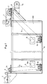
- guide rollers 2, 10, 10b, 2a, 2b, 2c are arranged in the bath tub BW receiving the liquid bath, of which the guide roller 2 is driven by a motor 3 via a countershaft 4 driven drive roller forms.
- the remaining guide rollers 10, 10b, 2a, 2b and 2c lead the endless, dash-dotted filter band 5, which is designed here as a carrying belt, from the guide roller 2a in the direction of the arrow S drawn obliquely downward into the bath tub BW, directing it into a horizontal plane above the floor 6 and then bring it back up out of the bath tub BW to the guide roller 2 which forms the drive roller.
- the roller 7 arranged on the end face of the bath tub BW unwound filter fleece 8 and forms together with this the filter belt 5.
- the filter belt 5 lies (Fig. 3) on in the direction of the band guide direction indicated by the arrow S parallel to each other running support surfaces here through the floor 6 of the bath tub BW arranged rail-shaped strips 9 are formed (Fig. 2 and Fig. 3).
- pressure rollers 10, 10b can be placed on the filter belt 5, which here (FIGS. 2 and 3) have ring bundles 10a, the arrangement width of which corresponds to the width of the support surfaces formed by the rail-shaped strips 9.
- the used filter fleece 8, after it has been led out of the bath tub BW, is lifted off the carrying belt and wound up on a roll 7a.
- the carrying belt on which the filter fleece 8 is placed here consists (FIG. 4) of an articulated chain, on the chain bolts 11 of which rows of a plurality of chain plates 12 are hinged next to one another at a distance across the belt width.
- This row of link plates 12 forms flat outer surfaces which rest on the support surfaces, here the rail-shaped strips 9, in such a way that each row forms groups of close-coupled link plates 12.
- These groups are arranged in the area above the respective support surfaces formed by the rail-shaped strips 9.
- the width of the two groups of link plates that are respectively outer on the width of the articulated chain is the same or larger here than the width of the ones below, here of the rail-shaped strips 9a formed support surfaces.
- the filter belt 5 formed by the joint chain 11, 12 thus formed and the filter fleece 8 lying thereon is, as shown in particular in the illustration according to FIG. 4, guided as a flat, non-sag filter surface over the floor 6 of the bath tub 5 and the filter fleece 8 can, for example, during this guidance when the vacuum is switched off, do not float, since the pressure rollers 10 with their ring collars 10a prevent this.
- guide rollers 16 and special pressure rollers 15 are arranged in a basket frame 14, which is lifted out of the position shown in the bath tub BW from this in the direction of the double arrow K shown, for example, into the position shown in broken lines can be lowered.
- the respective positioning of the basket frame 14 can be set and fixed in a manner not shown.
- a correspondingly designed basket frame, which only carries pressure rollers or also guide rollers and a circulating belt which can be driven around them, can also be used for the already described embodiment according to FIGS. 1 to 4, in which case the pressure rollers 10 shown there are not required.
- 5 support rollers 17 are mounted above the bottom 6 of the bath tub BW at intervals in the guide direction of the filter belt, and the pressure rollers 15 stored in the basket frame 14 can, when the basket frame 14 is lowered, into between them Carrier rollers 17 formed gap gaps are introduced; they press the filter belt 5 against the circumferential surface sections of the support rollers 17 forming the respective spacing gap.
- the circulating belt which is guided around the guide rollers 16 and the pressure rollers 15 consists of two endless support chains 18, to which rod bodies 19, which are located one behind the other, are connected in FIG the illustrated position of the basket frame 14 in the bath tub BW on the top of the filter belt 5.
- this filter belt 5 is guided through the bath tub BW by means of guide rollers 1, and the associated filter fleece is unwound from a roller 7 and placed on it, as in the previously explained embodiment.
- Guide rollers 16 have, as is apparent from FIGS. 6 and 8, on their circumference parallel driver recesses 20 which are adapted to the cross section of the rod body 19.
- the endless support chains 18 are guided in the region of their bypass around the pressure rollers 15 and the support rollers 17 in the manner shown in FIGS. 6 and 7 in lateral guide links 21 which are arranged in a fixed manner in the basket frame 14.
- the support rollers 17 have ring collars 17a, the circumferential ring surfaces of which, together with ring supports 39 arranged on the bath tub BW, form support surfaces for the central region and the sides of the filter belt 5.
- the filter belt rests on partially cylindrical support shells 37 which are also connected to the bath tub BW (FIGS. 6 and 7).
- These scratch profiles are each arranged on, here two adjacent pairs of circulation transport devices, here belt guides 23, which can be pressed against the profile rod 19 in an elastic manner in springs 24.
- the movements of the scraper profiles 22 generated by the band guides 23 are arranged at an angle ⁇ (FIG.
- a reversible motor 25 drives the belt guides 23 for the scratch profiles 22 (not shown here) via a shaft 26 and an angular drive 27.
- a worm 28 which meshes with a worm wheel 29, via which and a chain drive 30, 31 the endless support chains 18 with the rod bodies 19 are driven.
- the shaft 32 of the worm wheel 29 can be coupled and uncoupled via a clutch 33, the drive wheel 34, which drives the support rollers 17 and thus the filter belt 5, not shown here, via chains 35, 36.
- the transmission ratio between worm 28 and worm wheel 29 determines the ratio between the movement of the scraper profiles 22 via the rod body 19 and the movement of this rod body 19 in the guide direction of the endless support chains 18 (cf. Fig. 11), while the coupling between worm wheel 29 and sprocket 34 ensures the synchronism of endless support chains 18 and filter belt 5.
- the filter fleece 8 can be drawn from the roll 7 into the bath tub BW with the aid of the profile bars 19 rotating with the endless support chains 18, around the pressure rollers 15 and the support rollers 17 again leading upwards out of the Belt tub BW can be brought out.
- This operating position is suitable for liquids with a relatively low proportion of ferritic particles.
- the basket frame 14 can be raised and the endless support chain 18 can be driven at a higher speed than the filter belt 5; this when the clutch 33 is switched off.
- the contaminated filter fleece 8 is discharged from the bath tub BW via the deflection roller 1 and either introduced directly into containers (not shown) or unwound into balls in a manner also not shown.
- the rod body 19 can also consist of non-magnetic materials, and the device with the scratch profiles 22 is not required.
- the supply line for the untreated bath liquid into the bath tub BW is indicated by an arrow Z.
- the drain line 43 in the bottom 41a of the bath tub BW is located below the filter 44, which is shown schematically with an interrupted double line.
- the drain line 43 leads via a feed pump 45 into the flow divider 46.
- This consists of a vertical cylinder 46a with a guided in it and movable slide piston 47, which has a central feed recess 47a and two outlet recesses 47b and 47c, which branch radially outward from the feed recess 47a and are arranged axially offset from one another.
- outlet recesses 47b and 47c are each associated with outlet recesses 46b and 46c, of which the outlet recesses 46b lead back into the bath tub BW via a line 48, and the outlet recess 46c leads via a line 49 to a downstream storage tank (not shown).
- the slide piston 47 is connected via a piston rod 50 and lever links 51, 52 to a float 53 which floats on the bath liquid, the level of which is indicated by N.
- the flow divider according to FIGS. 14 and 15 is formed from two cylinder tubes 54 and 55 which are axially concentrically inserted one inside the other with their inner and outer surfaces.
- the outer cylinder tube 54 is firmly connected to a flange support ring 56, which, for example, is attached to a fixed support frame 58 by means of screws 57, to which the bath tub BW is fastened.
- axially parallel outlet slot recesses 59 and 60 are arranged in the lower and upper area, of which the lower 59 opens into the bath tub BW, not shown, while the upper 60, via pipes, also not shown 13, which is connected to the reservoir.
- the inner cylinder tube 55 is rotatably supported with bearing rollers 61 in the outer cylinder tube 54 and has an inlet opening 55a on its one end face, into which, according to the feed pump 45, the feed pump 45 after the training, not shown. 13 corresponds to incoming line 43 opens.
- the other side of the inner cylinder tube 55 is closed by a disk 62.
- a single-armed lever 64 which carries a floating body 65 at its free end, sits on this disk 62, fastened with screws 63.
- outlet recesses 66 and 67 are also arranged; Of these, the outlet recesses 66 are assigned to the outlet recess 60 and the outlet recess 67 to the outlet recess 59 of the outer cylinder tube 54.
- the device works as follows:
- the feed pump 45 (FIG. 13) sucks the liquid passing through it from the space below the filter belt 5 and thereby creates a negative pressure in this space.
- the resulting differential pressure as a result of the higher pressure in the space above the filter belt 5, if it has reached a predetermined maximum value, leads to the need to move the dirty length of the filter belt 5 out of the filter-effective position and to introduce the following, unpolluted length into this position. Since the surface of the support rollers 17 wrapped around by the filter belt 5 is larger than that of the pressure rollers 15 arranged between them, the filter belt 5 is transported with an approximately equal friction factor of both rollers despite the contact pressure caused by the differential pressure.
Applications Claiming Priority (4)
| Application Number | Priority Date | Filing Date | Title |
|---|---|---|---|
| DE4114603 | 1991-05-04 | ||
| DE4114603 | 1991-05-04 | ||
| DE9203370U DE9203370U1 (fr) | 1992-03-13 | 1992-03-13 | |
| DE9203370U | 1992-03-13 |
Publications (2)
| Publication Number | Publication Date |
|---|---|
| EP0512288A1 true EP0512288A1 (fr) | 1992-11-11 |
| EP0512288B1 EP0512288B1 (fr) | 1995-12-27 |
Family
ID=25903368
Family Applications (1)
| Application Number | Title | Priority Date | Filing Date |
|---|---|---|---|
| EP92106496A Expired - Lifetime EP0512288B1 (fr) | 1991-05-04 | 1992-04-15 | Filtre à bande pour séparer des impuretés des bains liquides |
Country Status (4)
| Country | Link |
|---|---|
| EP (1) | EP0512288B1 (fr) |
| JP (1) | JP3179557B2 (fr) |
| AT (1) | ATE132052T1 (fr) |
| DE (1) | DE59204795D1 (fr) |
Cited By (9)
| Publication number | Priority date | Publication date | Assignee | Title |
|---|---|---|---|---|
| EP0711589A1 (fr) | 1994-11-09 | 1996-05-15 | Sms Schloemann-Siemag Aktiengesellschaft | Dispositif à bandes filtrantes pour l'enlèvement de particules étrangères de bains liquides |
| FR2742671A1 (fr) * | 1995-12-20 | 1997-06-27 | Filtres Philippe Sa | Courroie de glissement pour filtre a bande et filtre a bande muni d'une pluralite de telles courroies |
| FR2787035A1 (fr) * | 1998-12-09 | 2000-06-16 | Filtres Monnet | Dispositif de separation solides/liquides et/ou liquides/liquides en continu sous vide autorisant la mise en oeuvre de media fragiles ou peu resistants a l'etat humide |
| FR2787034A1 (fr) * | 1998-12-09 | 2000-06-16 | Filtres Monnet | Dispositif de separation solides/liquides et/ou liquides/liquides en continu sous vide autorisant la mise en oeuvre de media fragiles ou peu resistants a l'etat humide |
| CN107988775A (zh) * | 2017-11-27 | 2018-05-04 | 上海乔力雅洗衣器材有限公司 | 一种用于衣物洗涤后展平的全自动展平机 |
| CN108379914A (zh) * | 2018-03-17 | 2018-08-10 | 刘志坤 | 一种稀土盐类的制备装置 |
| CN113476935A (zh) * | 2021-07-23 | 2021-10-08 | 谢金林 | 一种便于安装和拆卸的污水处理用转盘过滤机 |
| CN115284065A (zh) * | 2022-07-06 | 2022-11-04 | 日善电脑配件(嘉善)有限公司 | 一种废切削液分离用铁屑排除装置 |
| CN116874008A (zh) * | 2023-09-04 | 2023-10-13 | 湖南品清环保科技有限公司 | 一种工业废水浓缩蒸发冷凝设备及其使用方法 |
Families Citing this family (1)
| Publication number | Priority date | Publication date | Assignee | Title |
|---|---|---|---|---|
| JP5825891B2 (ja) * | 2011-07-07 | 2015-12-02 | 三菱重工業株式会社 | 循環液体濾過装置 |
Citations (8)
| Publication number | Priority date | Publication date | Assignee | Title |
|---|---|---|---|---|
| DE1179518B (de) * | 1960-02-20 | 1964-10-08 | Iarhewumia Rheinische Werkzeug | Walzenpresse zum Entwaessern von Klaerschlamm |
| FR1421665A (fr) * | 1964-12-04 | 1965-12-17 | Ajem Lab Inc | Filtre |
| DE1223806B (de) * | 1964-08-26 | 1966-09-01 | Bilabel Walzbau Montage | Bandfilter mit Vakuumsaugraum fuer das Filtrat unterhalb des oberen Trumes |
| GB1462304A (en) * | 1974-01-17 | 1977-01-26 | Hagihara T | Self-reconditioning filter apparatus for continuos removal of solids from a stream of liquid |
| US4289619A (en) * | 1980-08-11 | 1981-09-15 | Sampson Milo J | Material handling apparatus |
| EP0116009A1 (fr) * | 1983-02-03 | 1984-08-15 | Beloit Corporation | Méthode et mécanisme de lavage de fibres de pulpe de bois à contre-courant et en continu |
| GB2174014A (en) * | 1985-04-22 | 1986-10-29 | Gec Diesels Ltd | Moving belt filter |
| EP0458413A1 (fr) * | 1990-05-21 | 1991-11-27 | Pannevis B.V. | Procédé et dispositif pour la séparation d'un liquide d'un mélange solide-liquide |
Family Cites Families (4)
| Publication number | Priority date | Publication date | Assignee | Title |
|---|---|---|---|---|
| US3087620A (en) * | 1961-03-27 | 1963-04-30 | Hirs Gene | Filter apparatus |
| US3618772A (en) * | 1970-02-26 | 1971-11-09 | Gerald P Dietrick | Control system for a vacuum filter |
| US3704787A (en) * | 1970-11-23 | 1972-12-05 | Orien K Norton | Seal for disposable media filter apparatus |
| IT1232132B (it) * | 1989-07-05 | 1992-01-23 | Gi Pi S A S Di Alfonso Gallett | Filtro a depressione autopulente con mezzo filtrante permanente continuo, particolarmente per liquidi lubro-refrigeranti industriali |
-
1992
- 1992-04-15 AT AT92106496T patent/ATE132052T1/de not_active IP Right Cessation
- 1992-04-15 DE DE59204795T patent/DE59204795D1/de not_active Expired - Lifetime
- 1992-04-15 EP EP92106496A patent/EP0512288B1/fr not_active Expired - Lifetime
- 1992-04-30 JP JP11187392A patent/JP3179557B2/ja not_active Expired - Fee Related
Patent Citations (8)
| Publication number | Priority date | Publication date | Assignee | Title |
|---|---|---|---|---|
| DE1179518B (de) * | 1960-02-20 | 1964-10-08 | Iarhewumia Rheinische Werkzeug | Walzenpresse zum Entwaessern von Klaerschlamm |
| DE1223806B (de) * | 1964-08-26 | 1966-09-01 | Bilabel Walzbau Montage | Bandfilter mit Vakuumsaugraum fuer das Filtrat unterhalb des oberen Trumes |
| FR1421665A (fr) * | 1964-12-04 | 1965-12-17 | Ajem Lab Inc | Filtre |
| GB1462304A (en) * | 1974-01-17 | 1977-01-26 | Hagihara T | Self-reconditioning filter apparatus for continuos removal of solids from a stream of liquid |
| US4289619A (en) * | 1980-08-11 | 1981-09-15 | Sampson Milo J | Material handling apparatus |
| EP0116009A1 (fr) * | 1983-02-03 | 1984-08-15 | Beloit Corporation | Méthode et mécanisme de lavage de fibres de pulpe de bois à contre-courant et en continu |
| GB2174014A (en) * | 1985-04-22 | 1986-10-29 | Gec Diesels Ltd | Moving belt filter |
| EP0458413A1 (fr) * | 1990-05-21 | 1991-11-27 | Pannevis B.V. | Procédé et dispositif pour la séparation d'un liquide d'un mélange solide-liquide |
Cited By (12)
| Publication number | Priority date | Publication date | Assignee | Title |
|---|---|---|---|---|
| EP0711589A1 (fr) | 1994-11-09 | 1996-05-15 | Sms Schloemann-Siemag Aktiengesellschaft | Dispositif à bandes filtrantes pour l'enlèvement de particules étrangères de bains liquides |
| US5683581A (en) * | 1994-11-09 | 1997-11-04 | Sms Schloemann-Siemag Aktiengesellschaft | Belt-type filter apparatus for removing foreign particles from liquid baths |
| FR2742671A1 (fr) * | 1995-12-20 | 1997-06-27 | Filtres Philippe Sa | Courroie de glissement pour filtre a bande et filtre a bande muni d'une pluralite de telles courroies |
| FR2787035A1 (fr) * | 1998-12-09 | 2000-06-16 | Filtres Monnet | Dispositif de separation solides/liquides et/ou liquides/liquides en continu sous vide autorisant la mise en oeuvre de media fragiles ou peu resistants a l'etat humide |
| FR2787034A1 (fr) * | 1998-12-09 | 2000-06-16 | Filtres Monnet | Dispositif de separation solides/liquides et/ou liquides/liquides en continu sous vide autorisant la mise en oeuvre de media fragiles ou peu resistants a l'etat humide |
| CN107988775A (zh) * | 2017-11-27 | 2018-05-04 | 上海乔力雅洗衣器材有限公司 | 一种用于衣物洗涤后展平的全自动展平机 |
| CN108379914A (zh) * | 2018-03-17 | 2018-08-10 | 刘志坤 | 一种稀土盐类的制备装置 |
| CN113476935A (zh) * | 2021-07-23 | 2021-10-08 | 谢金林 | 一种便于安装和拆卸的污水处理用转盘过滤机 |
| CN115284065A (zh) * | 2022-07-06 | 2022-11-04 | 日善电脑配件(嘉善)有限公司 | 一种废切削液分离用铁屑排除装置 |
| CN115284065B (zh) * | 2022-07-06 | 2023-07-25 | 日善电脑配件(嘉善)有限公司 | 一种废切削液分离用铁屑排除装置 |
| CN116874008A (zh) * | 2023-09-04 | 2023-10-13 | 湖南品清环保科技有限公司 | 一种工业废水浓缩蒸发冷凝设备及其使用方法 |
| CN116874008B (zh) * | 2023-09-04 | 2023-11-17 | 湖南品清环保科技有限公司 | 一种工业废水浓缩蒸发冷凝设备及其使用方法 |
Also Published As
| Publication number | Publication date |
|---|---|
| ATE132052T1 (de) | 1996-01-15 |
| DE59204795D1 (de) | 1996-02-08 |
| JP3179557B2 (ja) | 2001-06-25 |
| EP0512288B1 (fr) | 1995-12-27 |
| JPH05228312A (ja) | 1993-09-07 |
Similar Documents
| Publication | Publication Date | Title |
|---|---|---|
| DE3322361C2 (fr) | ||
| CH670575A5 (fr) | ||
| EP0264899B1 (fr) | Dispositif de déshydratation de boues et de matières similaires | |
| DE3016750A1 (de) | Umlaufbandfiltervorrichtung | |
| EP0512288B1 (fr) | Filtre à bande pour séparer des impuretés des bains liquides | |
| DE3409826A1 (de) | Filtervorrichtung zum abscheiden von feststoffen aus fluessigkeiten | |
| DE4209054A1 (de) | Bandfilter zum ausbringen von fremdstoffpartikeln aus fluessigkeitsbaedern | |
| DE4243038A1 (de) | Horizontalbandfilter | |
| DE3326248C2 (fr) | ||
| DE4213200A1 (de) | Flüssigkeitsfilter | |
| DE1510174A1 (de) | Vorrichtung zum kontinuierlichen Nassbehandeln,insbesondere zum Waschen von losem faserfoermigen Material,beispielsweise Rohwolle | |
| DE3635766C2 (fr) | ||
| DE3830780C2 (fr) | ||
| EP0588230B1 (fr) | Dispositif de séparation et de fibration pour la séparation solide-liquide | |
| DE2306880B2 (de) | Saugbandfilter | |
| EP0391091B1 (fr) | Filtre à bande avec aspiration | |
| DE4137608C2 (de) | Vorrichtung zur Filterung von mit magnetisierbaren und nicht magnetisierbaren Feststoffen beladenen Flüssigkeiten | |
| DE2639493A1 (de) | Unterdruck-trommelfilter mit automatisch gesteuertem transport von einem oder mehreren baendern im gleichklang mit der filtertrommelbewegung zum ausfiltern von feststoffen aus fluessigkeiten | |
| DE3740992A1 (de) | Vorrichtung zum filtern von durch feststoffteilchen verunreinigten fluessigkeiten, insbesondere schmieroel, schneidemulsionen und dergleichen | |
| DE3910930C2 (fr) | ||
| DE2021389A1 (de) | Verfahren zum kontinuierlichen Entwassern von Suspensionen | |
| CH432476A (de) | Filtrierapparat | |
| WO1990006800A1 (fr) | Procede et dispositif pour separer des substances dans des melanges | |
| DE4205232C2 (de) | Unterdruck-Tauchfiltereinrichtung | |
| EP3372292B1 (fr) | Filtre à bande |
Legal Events
| Date | Code | Title | Description |
|---|---|---|---|
| PUAI | Public reference made under article 153(3) epc to a published international application that has entered the european phase |
Free format text: ORIGINAL CODE: 0009012 |
|
| 17P | Request for examination filed |
Effective date: 19920430 |
|
| AK | Designated contracting states |
Kind code of ref document: A1 Designated state(s): AT DE FR GB IT |
|
| 17Q | First examination report despatched |
Effective date: 19940720 |
|
| GRAA | (expected) grant |
Free format text: ORIGINAL CODE: 0009210 |
|
| AK | Designated contracting states |
Kind code of ref document: B1 Designated state(s): AT DE FR GB IT |
|
| REF | Corresponds to: |
Ref document number: 132052 Country of ref document: AT Date of ref document: 19960115 Kind code of ref document: T |
|
| REF | Corresponds to: |
Ref document number: 59204795 Country of ref document: DE Date of ref document: 19960208 |
|
| ITF | It: translation for a ep patent filed |
Owner name: STUDIO JAUMANN |
|
| PG25 | Lapsed in a contracting state [announced via postgrant information from national office to epo] |
Ref country code: AT Effective date: 19960415 |
|
| ET | Fr: translation filed | ||
| GBT | Gb: translation of ep patent filed (gb section 77(6)(a)/1977) |
Effective date: 19960322 |
|
| PLBE | No opposition filed within time limit |
Free format text: ORIGINAL CODE: 0009261 |
|
| STAA | Information on the status of an ep patent application or granted ep patent |
Free format text: STATUS: NO OPPOSITION FILED WITHIN TIME LIMIT |
|
| 26N | No opposition filed | ||
| PGFP | Annual fee paid to national office [announced via postgrant information from national office to epo] |
Ref country code: GB Payment date: 20000313 Year of fee payment: 9 |
|
| PG25 | Lapsed in a contracting state [announced via postgrant information from national office to epo] |
Ref country code: GB Free format text: LAPSE BECAUSE OF NON-PAYMENT OF DUE FEES Effective date: 20010415 |
|
| GBPC | Gb: european patent ceased through non-payment of renewal fee |
Effective date: 20010415 |
|
| PGFP | Annual fee paid to national office [announced via postgrant information from national office to epo] |
Ref country code: IT Payment date: 20100426 Year of fee payment: 19 |
|
| PGFP | Annual fee paid to national office [announced via postgrant information from national office to epo] |
Ref country code: FR Payment date: 20111018 Year of fee payment: 20 |
|
| REG | Reference to a national code |
Ref country code: DE Ref legal event code: R071 Ref document number: 59204795 Country of ref document: DE |
|
| REG | Reference to a national code |
Ref country code: DE Ref legal event code: R071 Ref document number: 59204795 Country of ref document: DE |
|
| PG25 | Lapsed in a contracting state [announced via postgrant information from national office to epo] |
Ref country code: DE Free format text: LAPSE BECAUSE OF EXPIRATION OF PROTECTION Effective date: 20120417 |
|
| PGFP | Annual fee paid to national office [announced via postgrant information from national office to epo] |
Ref country code: DE Payment date: 20110722 Year of fee payment: 20 |