EP0511034A2 - Refuse container and an actuating mechanism for the container trapdoor - Google Patents
Refuse container and an actuating mechanism for the container trapdoor Download PDFInfo
- Publication number
- EP0511034A2 EP0511034A2 EP92400794A EP92400794A EP0511034A2 EP 0511034 A2 EP0511034 A2 EP 0511034A2 EP 92400794 A EP92400794 A EP 92400794A EP 92400794 A EP92400794 A EP 92400794A EP 0511034 A2 EP0511034 A2 EP 0511034A2
- Authority
- EP
- European Patent Office
- Prior art keywords
- container
- pedal
- hatch
- articulated
- opening
- Prior art date
- Legal status (The legal status is an assumption and is not a legal conclusion. Google has not performed a legal analysis and makes no representation as to the accuracy of the status listed.)
- Withdrawn
Links
Images


Classifications
-
- B—PERFORMING OPERATIONS; TRANSPORTING
- B65—CONVEYING; PACKING; STORING; HANDLING THIN OR FILAMENTARY MATERIAL
- B65F—GATHERING OR REMOVAL OF DOMESTIC OR LIKE REFUSE
- B65F1/00—Refuse receptacles; Accessories therefor
- B65F1/12—Refuse receptacles; Accessories therefor with devices facilitating emptying
- B65F1/125—Features allowing the receptacle to be lifted and emptied by its bottom
Definitions
- the invention relates to a control mechanism for a hatch with which a tank or container for collecting waste is fitted.
- the invention also relates to the container as such which can in particular be used for collecting paper (newspapers, magazines ).
- containers In the general context of the devices used for collecting waste, containers are already known comprising a bottom with an opening normally closed by an articulated hatch used for emptying the container, hooking means for locking the hatch in the closed position, a control mechanism for said attachment means for causing the opening or closing of this hatch and force recovery means extending substantially between a belt surrounding said bottom opening of the container and an upper lifting ring of this same container.
- Such a container is for example described in patent FR-A-2,592,636.
- the force recovery means can then consist of a mast or a frame extending internally in the central part of the container, near its vertical central axis, thus allowing a mechanically satisfactory path of efforts.
- the aforementioned means for internal recovery of forces will have the shape of an arch. connected at its ends to two substantially opposite zones of said belt surrounding the bottom opening of the container, passing substantially through the top of this container where the hoop is connected to the lifting ring, which protrudes above the container.
- the interior reinforcement of the container will present a balance compatible with the different possible uses of the latter.
- the first aforementioned pedal may be in the form of a hoop connected at its ends to the hatch.
- a container 1 which can be used for the collection of soft and / or compactable waste such as paper, cardboard or objects made of these materials.
- the container 1 consists of a storage tank comprising outer peripheral walls of the envelope 3 forming a sort of bell above a bottom 5.
- the bottom 5 has a wide opening 7 (FIG. 3) allowing the container to be emptied and that a bottom door or door 9 can completely block it.
- the hatch 9 is articulated in rotation relative to the container about a substantially horizontal axis 9a (when the container is arranged vertically), via hinges 11 which can be carried by a metal reinforcing belt 13 surrounding or bordering the opening 7 on its periphery, as illustrated in Figure 3.
- the hatch 9 can also be closed or locked to the container by means attachment 15 actuable by an articulated control mechanism identified as a whole 17 in FIG. 1.
- the force recovery means consist in this case of a metal hoop marked 10 in each of the figures.
- This arch 10 has substantially the shape of an inverted U. Its lower ends 10a, 10b are mechanically linked (directly or indirectly) to the lower belt 13, while its upper central part cooperates with a connection plate 14 extending under the top of the tank. To this plate 14 is fixed the lifting ring 12.
- the arch 10 extends over its entire length in the immediate vicinity of the external walls 3 of the tank so as to free up the maximum useful storage volume of the latter.
- the arch 10 can be arranged in a substantially median vertical plane of the container, as illustrated in the figures.
- This bolt comprises in the lower part a hook 23 able to cooperate with a ring or a lug 25 attached internally to hatch 9.
- the bolt 19 has a protrusion 27 intended to come to cooperate with a tilting latch 29 itself articulated in rotation around a pivot with horizontal axis 31 carried by the tank.
- the latch 29 comprises a retractable latch 33 which can pivot between two stops around a horizontal axis 35.
- all of these parts are arranged in the immediate vicinity of a side edge of the tank, thereby freeing up the maximum useful internal volume for storing the latter.
- the means 15 in question are located just behind a boss 59 of the outer lateral wall 3 of the container, formed laterally at the base of the latter and acting as an outer protective casing. Inside the container, the protection of these means can be ensured by a flange 60 ( Figures 1 and 2) extending substantially opposite the boss and to which will then be connected one of the distal ends (10b) of the hoop 10 as well as the bottom belt 13 which will be interrupted at 13a and 13b, the flange 60 transmitting the forces from one part to another.
- the means 15 with their boss 59 are situated substantially opposite, or at least at a distance from, the axis of articulation of the hatch, still shown at 9a in FIG. 2.
- the control mechanism of the fastening means 15, 25 is in this case supplemented by another pedal, called the first pedal 41, articulated in rotation about pivots with horizontal axis 43 situated near the vertical median plane 1a of the container, as shown in FIGS. 1 and 3, with however a slight lateral offset relative to the axis 39 of the second pedal and slightly below the latter, so as to be able to "hang” under the hatch in the low rotational position (marked in solid lines in FIGS. 1 and 2).
- this pedal 41 which will ensure a distribution over a relatively large area of the load that can be supported by the container, in particular when the latter is full.
- this first "lower" pedal 41 may be in the form of a " U- shaped" metal hoop articulated relative to the hatch at the top of its two lateral end branches 41a, 41b. This hoop will then advantageously extend over the greater part of the width of the tank, without overflowing under the second pedal 37 but nevertheless extending to a level below that of the latter when it is in position low rotation.
- a horizontal tab 45 projecting laterally from the first pedal has been provided, this tab extending just below the second pedal 37, without however being hampered by it during the downward rotational movement. of the first pedal.
- the container is first placed on the ground.
- the positioning of the articulation axes 43 and 39 of the first and second pedals is provided so that these two pedals are substantially camouflaged or retracted at the level of the hatch under which they then extend substantially horizontally.
- the hatch is also locked, the tab 25 being attached to the hook 23.
- the pedals stop, for example under the effect of a stop (not shown).
- the first pedal 41 then hangs down to a level lower than that of the second and the hatch is of course always closed.
Abstract
Description
L'invention concerne un mécanisme de commande d'une trappe dont est équipé une cuve ou un conteneur pour la collecte des déchets.The invention relates to a control mechanism for a hatch with which a tank or container for collecting waste is fitted.
L'invention se rapporte également au conteneur en tant que tel qui peut notamment être utilisé pour la collecte du papier (journaux, revues...).The invention also relates to the container as such which can in particular be used for collecting paper (newspapers, magazines ...).
Depuis un certain temps se fait jour, notamment dans les villes, un besoin de récupération des papiers usagés.For some time now, especially in cities, there has been a need to recover used paper.
Pour permettre la collecte de tels papiers en relativement grande quantité, il a été envisagé de recourir à des conteneurs comparables à ceux utilisés pour la collecte du verre.To allow the collection of such papers in relatively large quantities, it has been envisaged to use containers comparable to those used for collecting glass.
Mais il s'est avéré que cette collecte d'article ou de substance relativement "molle" ou déformable lorsqu'elle n'est pas compactée posait des problèmes spécifiques non rencontrés dans le cadre de la collecte d'objets en verre compte tenu de la nature différente des matériaux.However, it turned out that this collection of relatively “soft” or deformable article or substance when it is not compacted poses specific problems not encountered in the context of the collection of glass objects given the different nature of materials.
Dans le cadre général des appareils utilisés pour la collecte des déchets, on connaît déjà des conteneurs comprenant un fond avec une ouverture normalement fermée par une trappe articulée utilisée pour la vidange du conteneur, des moyens d'accrochage pour verrouiller la trappe en position fermée, un mécanisme de commande desdits moyens d'accrochage pour provoquer l'ouverture ou la fermeture de cette trappe et des moyens de reprise d'efforts s'étendant sensiblement entre une ceinture entourant ladite ouverture de fond du conteneur et un anneau supérieur de levage de ce même conteneur.In the general context of the devices used for collecting waste, containers are already known comprising a bottom with an opening normally closed by an articulated hatch used for emptying the container, hooking means for locking the hatch in the closed position, a control mechanism for said attachment means for causing the opening or closing of this hatch and force recovery means extending substantially between a belt surrounding said bottom opening of the container and an upper lifting ring of this same container.
Un tel conteneur est par exemple décrit au brevet FR-A-2 592 636.Such a container is for example described in patent FR-A-2,592,636.
Mais dans ce brevet, les moyens de reprise d'efforts et tant le mécanisme de commande que les moyens d'accrochage de la trappe sont situés dans la zone centrale du conteneur.But in this patent, the force recovery means and both the control mechanism and the hooking means of the hatch are located in the central zone of the container.
Une telle disposition paraît de prime abord tout à fait adaptée dans la mesure où les moyens de reprise d'efforts peuvent alors consister en un mât ou en une armature s'étendant intérieurement en partie centrale du conteneur, à proximité de son axe central vertical, permettant ainsi un cheminement mécaniquement satisfaisant des efforts.At first glance, such an arrangement seems entirely suitable insofar as the force recovery means can then consist of a mast or a frame extending internally in the central part of the container, near its vertical central axis, thus allowing a mechanically satisfactory path of efforts.
Après qu'une série d'essais ait été menée avec un tel type de conteneur pour des utilisations concernant la collecte de déchets divers, notamment en verre et en papier ou carton, des problèmes d'adaptation sont apparus.After a series of tests was carried out with such a type of container for uses relating to the collection of various wastes, in particular glass and paper or cardboard, problems of adaptation appeared.
Il s'est en particulier avéré que la disposition centrale des moyens de reprise d'efforts pouvait gêner le remplissage du conteneur et surtout son vidage, en faisant obstacle aux paquets compacts, de papier notamment.In particular, it turned out that the central arrangement of the force recovery means could hinder the filling of the container and especially its emptying, by obstructing compact packages, in particular of paper.
Il s'est également avéré que si l'on déplaçait ces moyens de reprise d'efforts, cela créait une difficulté supplémentaire liée au nécessaire équilibre du conteneur lorsque celui-ci est soulevé et qu'il doit être vidé, le conteneur devant alors être suffisamment bien équilibré pour que son fond soit sensiblement horizontal afin d'éviter tout défaut de manoeuvre à l'ouverture, lors de la vidange ou à la fermeture de la trappe.It has also been found that if these means of force recovery were moved, this created an additional difficulty linked to the necessary balance of the container when it is lifted and that it must be emptied, the container then having to be sufficiently well balanced so that its bottom is substantially horizontal in order to avoid any operating defect at the opening, during the emptying or at the closing of the hatch.
Dans l'invention, ces différents problèmes ont été résolus en prévoyant, selon une caractéristique importante de cette invention, que les moyens de reprise d'efforts et les moyens d'accrochage de la trappe avec leur mécanisme de commande soient, à l'intérieur de ce conteneur, déportés latéralement, à proximité de parois périphériques de ce dernier délimitant extérieurement son volume intérieur utile, lesdits moyens d'accrochage et leur mécanisme de commande étant alors situés à distance de l'axe d'articulation de la trappe.In the invention, these various problems have been resolved by providing, according to an important characteristic of this invention, that the force recovery means and the means for hooking the hatch with their control mechanism are, inside of this container, offset laterally, near peripheral walls of the latter externally delimiting its useful internal volume, said attachment means and their control mechanism then being located at a distance from the articulation axis of the hatch.
De préférence, les moyens précités de reprise intérieure d'efforts présenteront la forme d'un arceau raccordé à ses extrémités à deux zones sensiblement opposées de ladite ceinture entourant l'ouverture de fond du conteneur, en passant sensiblement par le sommet de ce conteneur où l'arceau est relié à l'anneau de levage, lequel fait saillie au-dessus du conteneur.Preferably, the aforementioned means for internal recovery of forces will have the shape of an arch. connected at its ends to two substantially opposite zones of said belt surrounding the bottom opening of the container, passing substantially through the top of this container where the hoop is connected to the lifting ring, which protrudes above the container.
Ainsi, l'armature de renforcement intérieure du conteneur présentera-t-elle un équilibre compatible avec les différentes utilisations possibles de ce dernier.Thus, the interior reinforcement of the container will present a balance compatible with the different possible uses of the latter.
Selon une autre caractéristique de l'invention, dans la mesure où le conteneur est en particulier adapté à la collecte de substances ayant une consistance proche de celle du papier ou du carton, le mécanisme de commande des moyens d'accrochage de la trappe pourra comprendre :
- une première pédale portée par la trappe et articulée en rotation par rapport à elle le long d'un axe sensiblement horizontal, cette première pédale s'étendant sous la trappe le long de toute une partie de cette dernière,pour répartir la charge du conteneur sur une surface de contact relativement importante ou allongée, lorsque ladite pédale est dans un état d'appui (par exemple à l'intérieur de la benne de récupération),
- et des moyens complémentaires d'actionnement sollicités par cette première pédale lorsque celle-ci, partant d'une position de rotation basse, pivote par appui autour de son axe vers une position de rotation haute pour provoquer la manoeuvre desdits moyens d'accrochage en vue de l'ouverture de la trappe.
- a first pedal carried by the hatch and articulated in rotation relative to it along a substantially horizontal axis, this first pedal extending under the hatch along a whole part of the latter, for distributing the load of the container over a relatively large or elongated contact surface, when said pedal is in a supported state (for example inside the recovery bucket),
- and additional actuation means requested by this first pedal when the latter, starting from a low rotational position, pivots by pressing about its axis towards a high rotational position to cause the operation of said hooking means in view opening the hatch.
Dans un mode préféré de réalisation, on notera encore que la première pédale précitée pourra se présenter sous la forme d'un arceau raccordé à ses extrémités à la trappe.In a preferred embodiment, it will also be noted that the first aforementioned pedal may be in the form of a hoop connected at its ends to the hatch.
D'autres caractéristiques et avantages de l'invention pourront encore apparaître de la description qui va suivre faite en référence aux dessins d'accompagnement donnés uniquement à titre d'exemple non limitatifs et dans lesquels :
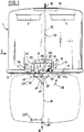
- la figure 1 est une vue schématique de face d'un conteneur conforme à l'invention équipé du mécanisme de commande également objet de l'invention, étant remarqué que la trappe dont est muni ce conteneur apparaît en traits mixtes dans sa position ouverte,
- la figure 2 est une vue de côté dans le sens de la flèche II de la figure 1, la trappe, ainsi que la première pédale du mécanisme de commande, étant à nouveau représentées en traits mixtes dans une position de pleine ouverture de cette trappe,
- la figure 3 est une vue de dessous du conteneur, dans le sens de la flèche III de la figure 1 (toujours en vue schématique).
- FIG. 1 is a schematic front view of a container according to the invention equipped with the control mechanism also subject of the invention, it being noted that the hatch with which this container is provided appears in dashed lines in its open position,
- FIG. 2 is a side view in the direction of arrow II in FIG. 1, the hatch, as well as the first pedal of the control mechanism, being again shown in phantom in a fully open position of this hatch,
- Figure 3 is a bottom view of the container, in the direction of arrow III of Figure 1 (still in schematic view).
Sur les figures, on voit donc illustré un conteneur 1 pouvant être utilisé pour la collecte de déchets mous et/ou compactables tels que du papier, du carton ou des objets réalisés en ces matières.In the figures, there is therefore illustrated a
Le conteneur 1 consiste en une cuve de stockage comprenant des parois périphériques extérieures d'enveloppe 3 formant une sorte de cloche au-dessus d'un fond 5.The
Des orifices latéraux 4 ménagés dans la paroi de cette cloche permettent de jeter les déchets à l'intérieur de la cuve.
Le fond 5 présente une large ouverture 7 (figure 3) permettant de vider le conteneur et qu'une trappe ou porte de fond 9 peut venir obturer entièrement.The
La trappe 9 est articulée en rotation par rapport au conteneur autour d'un axe sensiblement horizontal 9a (lorsque le conteneur est disposé verticalement), via des charnières 11 pouvant être portées par une ceinture métallique de renforcement 13 entourant ou bordant l'ouverture 7 sur sa périphérie, comme cela est illustré sur la figure 3.The
La trappe 9 peut par ailleurs être fermée ou verrouillée au conteneur par l'intermédiaire de moyens d'accrochage 15 actionnables par un mécanisme de commande articulé repéré dans son ensemble 17 sur la figure 1.The
A l'intérieur de la cuve, repérée 2, s'étendent des moyens 10 de reprise d'efforts reliant mécaniquement la ceinture métallique de renforcement inférieur 13 et un anneau de levage supérieur 12 qui fait saillie au-dessus de la cuve 2, sensiblement dans l'axe central vertical 2a de celle-ci.Inside the tank, marked 2, extend
Conformément à une caractéristique importante de l'invention, les moyens de reprise d'efforts consistent en l'espèce en un arceau métallique repéré 10 sur chacune des figures. Cet arceau 10 présente sensiblement la forme d'un U inversé. Ses extrémités inférieures 10a, 10b sont mécaniquement liées (directement ou indirectement )à la ceinture inférieure 13, tandis que sa partie centrale supérieure vient coopérer avec une plaque de liaison 14 s'étendant sous le sommet de la cuve. A cette plaque 14 est fixé l'anneau de levage 12.In accordance with an important characteristic of the invention, the force recovery means consist in this case of a metal hoop marked 10 in each of the figures. This
On remarquera que l'arceau 10 s'étend sur toute sa longueur à proximité immédiate des parois extérieures 3 de la cuve de manière à dégager au maximum le volume utile de stockage de cette dernière. Pour un bon équilibrage, l'arceau 10 pourra être disposé dans un plan vertical sensiblement médian du conteneur, comme cela est illustré sur les figures.It will be noted that the
En ce qui concerne les moyens d'accrochage 15 et une partie de leur mécanisme de commande 17 mentionné ci-dessus, on notera qu'ils étaient déjà décrits dans la demande de brevet français FR-A-87 17074 à laquelle on pourra se reporter utilement.As regards the attachment means 15 and part of their
On retrouve ainsi un pène 19 basculant articulé en rotation autour d'un pivot à axe horizontal 21 porté par la cuve 2. Ce pène comporte en partie inférieure un crochet 23 apte à coopérer avec un anneau ou une patte d'accrochage 25 fixé intérieurement à la trappe 9.We thus find a tilting bolt 19 articulated in rotation around a pivot with a
En partie supérieure opposée, le pène 19 présente une excroissance 27 destinée à venir coopérer avec un loquet basculant 29 lui-même articulé en rotation autour d'un pivot à axe horizontal 31 porté par la cuve.In the opposite upper part, the bolt 19 has a protrusion 27 intended to come to cooperate with a tilting
Le loquet 29 comprend un loqueteau escamotable 33 pouvant pivoter entre deux butées autour d'un axe horizontal 35.The
On retrouve également la pédale 37, appelée en l'espèce seconde pédale, articulée en rotation autour d'un pivot à axe horizontal 39 porté par la cuve (ou sa ceinture de fond). Cette seconde pédale qui peut présenter la forme d'une plaque relativement étroite (voir figure 2) fait saillie sous la trappe en position non sollicitée, comme on le voit sur la figure 2.We also find the
Conformément à l'invention, toutes ces pièces sont disposées à proximité immédiate d'un bord de côté de la cuve, dégageant ainsi au maximum le volume intérieur utile de stockage de cette dernière.In accordance with the invention, all of these parts are arranged in the immediate vicinity of a side edge of the tank, thereby freeing up the maximum useful internal volume for storing the latter.
Extérieurement, les moyens 15 en question sont situés juste derrière un bossage 59 de la paroi latérale extérieure 3 du conteneur, formé latéralement à la base de ce dernier et faisant office de carter extérieur de protection. A l'intérieur du conteneur, la protection de ces moyens pourra être assurée par un flasque 60 (figures 1 et 2) s'étendant sensiblement en regard du bossage et auquel sera alors raccordé l'une des extrémités distales (10b) de l'arceau 10 ainsi que la ceinture de fond 13 qui sera interrompue en 13a et 13b, le-flasque 60 transmettant les efforts d'une pièce à l'autre.Externally, the means 15 in question are located just behind a
On remarquera que les moyens 15 avec leur bossage 59 sont situés sensiblement à l'opposé, ou du moins à distance, de l'axe d'articulation de la trappe, toujours figuré en 9a sur la figure 2.It will be noted that the means 15 with their
Au vu des figures 1 et 2, on comprendra que le mécanisme de commande des moyens d'accrochage 15, 25 est en l'espèce complété par une autre pédale, dite première pédale 41, articulée en rotation autour de pivots à axe horizontal 43 situés à proximité du plan médian vertical 1a du conteneur, comme montré figures 1 et 3, avec toutefois un léger décalage latéral par rapport à l'axe 39 de la seconde pédale et légèrement en-dessous de ce dernier, de manière à pouvoir "pendre" sous la trappe en position de rotation basse (repérée en traits pleins sur les figures 1 et 2).In view of Figures 1 and 2, it will be understood that the control mechanism of the fastening means 15, 25 is in this case supplemented by another pedal, called the
On remarquera la dimension, notamment la longueur,importante de cette pédale 41 qui permettra d'assurer une répartition sur une surface relativement importante de la charge pouvant être supportée par le conteneur, en particulier lorsque celui-ci est plein.Note the large dimension, in particular the length, of this
Pour une utilisation efficace sur des surfaces d'appui pouvant consister en du papier non compacté, il pourra être préférable que cette première pédale "inférieure" 41 se présente alors sous la forme d'un arceau métallique "en U" articulé par rapport à la trappe au sommet de ses deux branches latérales d'extrémité 41a, 41b. Cet arceau s'étendra alors avantageusement sur la plus grande partie de la largeur de la cuve, sans déborder sous la seconde pédale 37 mais en s'étendant malgré tout jusqu'à un niveau inférieur à celui de cette dernière lorsqu'elle est en position de rotation basse.For effective use on bearing surfaces which may consist of non-compacted paper, it may be preferable for this first "lower"
Pour pouvoir agir sur la seconde pédale, une patte horizontale 45 faisant saillie latéralement à la première pédale a été prévue, cette patte s'étendant juste en-dessous de la seconde pédale 37, sans toutefois être gênée par elle lors du mouvement de rotation descendant de la première pédale.To be able to act on the second pedal, a
Le principe de fonctionnement d'un tel mécanisme est comparable à celui décrit dans la demande précitée FR-A-87 17074.The operating principle of such a mechanism is comparable to that described in the aforementioned application FR-A-87 17074.
On rappellera ci-après brièvement ce principe.This principle will be briefly recalled below.
Le conteneur est tout d'abord posé au sol.The container is first placed on the ground.
Sa trappe est fermée.Its hatch is closed.
Le positionnement des axes d'articulation 43 et 39 des première et seconde pédales est prévu de manière que ces deux pédales soient sensiblement camouflées ou escamotées au niveau de la trappe sous laquelle elles s'étendent alors sensiblement horizontalement.The positioning of the
La trappe est par ailleurs verrouillée, la patte 25 étant accrochée au crochet 23.The hatch is also locked, the
Pour vider le conteneur alors supposé plein, on vient alors le soulever par son anneau de levage 12. On notera que les efforts supportés par le conteneur sont alors limités, étant transmis et répartis jusqu'à la base de la cuve par l'arceau périphérique 10 puis par la ceinture de renforcement de fond 13 (via éventuellement le flasque 60).To empty the container then assumed to be full, we then lift it by its
Lors du levage de la cuve, et du fait de leur poids, les pédales pivotent elles-mêmes de leur position de rotation haute vers leur position basse (voir figures 1 et 2, traits pleins), entraînant la rotation du loquet 29 dont le loqueteau 33 s'escamote par rotation au passage de l'excroissance 27 du pène 19.When lifting the tank, and due to their weight, the pedals pivot themselves from their high rotation position to their low position (see Figures 1 and 2, solid lines), causing the
On notera que le mouvement de rotation (dans les deux sens) du loquet 29 est ici guidé par une tige 47 articulée en rotation à ses deux extrémités opposées autour de deux pivots portés respectivement par le loquet et par la seconde pédale 37.It will be noted that the rotational movement (in both directions) of the
Parvenues en position basse, les pédales s'arrêtent, par exemple sous l'effet d'une butée (non représentée).When they reach the low position, the pedals stop, for example under the effect of a stop (not shown).
La première pédale 41 pend alors jusqu'à un niveau inférieur à celui de la seconde et la trappe est bien entendu toujours fermée.The
Pour ouvrir cette trappe, on va venir faire reposer le conteneur sur un appui, tel par exemple que le fond d'une benne de camion de ramassage. Même si cette benne est déjà partiellement remplie de déchets de papiers, la première pédale 41 va malgré tout pouvoir agir efficacement du fait de sa conformation, sa portée étant répartie sur une surface d'appui étendue. Ainsi, elle va pivoter en direction de sa position haute (flèche 49, figure 1) pour agir sur la seconde pédale 37 via la patte latérale d'actionnement 45. La seconde pédale est alors repoussée vers le haut et sa rotation provoque la remontée du loquet 29 dont le loqueteau (alors bloqué en rotation) vient pousser l'excroissance arrière 27 du pène, provoquant son basculement vers l'avant dans le sens de la flèche 51 de la figure 1, libérant ainsi la patte d'accrochage 25 de la trappe qui s'ouvre alors, permettant au contenu de la cuve de tomber.To open this hatch, we will come to rest the container on a support, such as for example the bottom of a pickup truck tipper. Even if this bucket is already partially filled with waste paper, the
Une fois vidé, le conteneur est redescendu, l'angle d'ouverture de la trappe ayant été adapté pour assurer sa fermeture "naturelle" lors de cette redescente, dans le sens de la flèche 53 de la figure 2.Once emptied, the container is lowered, the opening angle of the hatch having been adapted to ensure its "natural" closing during this lowering, in the direction of
Le replacement en position d'origine du conteneur provoque la fermeture de la trappe avec un nouveau verrouillage du pène et du crochet, les pédales se replaçant d'elles-mêmes sous la trappe en position escamotée, parallèlement au fond. Le conteneur est alors à nouveau prêt à être rempli.The replacement of the container in the original position causes the hatch to close with a new locking of the bolt and the hook, the pedals replacing themselves under the hatch in the retracted position, parallel to the bottom. The container is then again ready to be filled.
Claims (10)
Applications Claiming Priority (2)
| Application Number | Priority Date | Filing Date | Title |
|---|---|---|---|
| FR9103801A FR2674511B1 (en) | 1991-03-28 | 1991-03-28 | WASTE CONTAINER AND CONTROL MECHANISM OF A HATCH EQUIPPED WITH THIS CONTAINER. |
| FR9103801 | 1991-03-28 |
Publications (2)
| Publication Number | Publication Date |
|---|---|
| EP0511034A2 true EP0511034A2 (en) | 1992-10-28 |
| EP0511034A3 EP0511034A3 (en) | 1993-02-03 |
Family
ID=9411237
Family Applications (1)
| Application Number | Title | Priority Date | Filing Date |
|---|---|---|---|
| EP19920400794 Withdrawn EP0511034A3 (en) | 1991-03-28 | 1992-03-24 | Refuse container and an actuating mechanism for the container trapdoor |
Country Status (2)
| Country | Link |
|---|---|
| EP (1) | EP0511034A3 (en) |
| FR (1) | FR2674511B1 (en) |
Cited By (4)
| Publication number | Priority date | Publication date | Assignee | Title |
|---|---|---|---|---|
| CN105836346A (en) * | 2016-05-17 | 2016-08-10 | 安徽九洲环保设备有限公司 | Locking device of embedded garbage can |
| CN107512508A (en) * | 2017-08-10 | 2017-12-26 | 张洁 | A kind of dormitory rubbish focuses on method |
| CN107521884A (en) * | 2017-08-10 | 2017-12-29 | 张洁 | A kind of dormitory rubbish automatic processing device |
| CN108656194A (en) * | 2018-07-13 | 2018-10-16 | 厦门盈趣科技股份有限公司 | Door closure linked double open mechanism and electronic cutting machine |
Citations (4)
| Publication number | Priority date | Publication date | Assignee | Title |
|---|---|---|---|---|
| DE2651561A1 (en) * | 1975-11-13 | 1977-05-18 | Otto Mueller | Spring loaded bottom discharge skip - partly self-closing double flaps shut in succession with overlap for sealing |
| DE2715992A1 (en) * | 1977-04-09 | 1978-10-12 | Werner Puhlmann | RECEIVED GLASS COLLECTORS |
| FR2555145A1 (en) * | 1983-11-21 | 1985-05-24 | Monin Entreprise | Container which empties itself by means of an opening bottom system. |
| FR2577904A1 (en) * | 1985-02-27 | 1986-08-29 | Loos Remy | Dual-function urban waste bin |
Family Cites Families (3)
| Publication number | Priority date | Publication date | Assignee | Title |
|---|---|---|---|---|
| US3343725A (en) * | 1965-06-09 | 1967-09-26 | Hoover Ball & Bearing Co | Bottom discharge bin |
| DE3776037D1 (en) * | 1986-08-16 | 1992-02-27 | Empteezy Ltd | SELF-EMPTY CONTAINER. |
| FR2624109B1 (en) * | 1987-12-08 | 1990-05-25 | Allibert Sa | CONTAINER COMPRISING A DRAIN DOOR WITH IMPROVED LOCKING / UNLOCKING MECHANISM |
-
1991
- 1991-03-28 FR FR9103801A patent/FR2674511B1/en not_active Expired - Fee Related
-
1992
- 1992-03-24 EP EP19920400794 patent/EP0511034A3/en not_active Withdrawn
Patent Citations (4)
| Publication number | Priority date | Publication date | Assignee | Title |
|---|---|---|---|---|
| DE2651561A1 (en) * | 1975-11-13 | 1977-05-18 | Otto Mueller | Spring loaded bottom discharge skip - partly self-closing double flaps shut in succession with overlap for sealing |
| DE2715992A1 (en) * | 1977-04-09 | 1978-10-12 | Werner Puhlmann | RECEIVED GLASS COLLECTORS |
| FR2555145A1 (en) * | 1983-11-21 | 1985-05-24 | Monin Entreprise | Container which empties itself by means of an opening bottom system. |
| FR2577904A1 (en) * | 1985-02-27 | 1986-08-29 | Loos Remy | Dual-function urban waste bin |
Cited By (5)
| Publication number | Priority date | Publication date | Assignee | Title |
|---|---|---|---|---|
| CN105836346A (en) * | 2016-05-17 | 2016-08-10 | 安徽九洲环保设备有限公司 | Locking device of embedded garbage can |
| CN107512508A (en) * | 2017-08-10 | 2017-12-26 | 张洁 | A kind of dormitory rubbish focuses on method |
| CN107521884A (en) * | 2017-08-10 | 2017-12-29 | 张洁 | A kind of dormitory rubbish automatic processing device |
| CN108656194A (en) * | 2018-07-13 | 2018-10-16 | 厦门盈趣科技股份有限公司 | Door closure linked double open mechanism and electronic cutting machine |
| CN108656194B (en) * | 2018-07-13 | 2023-06-09 | 厦门盈趣科技股份有限公司 | Door cover linkage double-opening mechanism and electronic cutting machine |
Also Published As
| Publication number | Publication date |
|---|---|
| EP0511034A3 (en) | 1993-02-03 |
| FR2674511B1 (en) | 1994-10-14 |
| FR2674511A1 (en) | 1992-10-02 |
Similar Documents
| Publication | Publication Date | Title |
|---|---|---|
| EP1081063B1 (en) | Device for automatically gravity-operated locking and unlocking of the lid of a container and container equipped with such a device | |
| US4405278A (en) | Self-emptying dump box | |
| FR2479783A1 (en) | Refuse bin lifting and tipping mechanism - has two latches catching in brackets in bin wall and actuated by hydraulic cylinders | |
| EP0511034A2 (en) | Refuse container and an actuating mechanism for the container trapdoor | |
| FR2500425A1 (en) | Handler to lift and tilt receptacles - has oscillating arms with hydraulic rams to support grip for receptacle | |
| EP0219385B1 (en) | Paper basket | |
| FR2459779A1 (en) | Container hoist with lifting frame - is actuated by hydraulic jacks operated in support frame with sliding central section | |
| CH632217A5 (en) | DEVICE FOR STACKING SOLID LOADS IN A RECEPTACLE. | |
| FR2759680A1 (en) | Container with opening base, e.g. for recyclable materials | |
| FR3010988A1 (en) | WASTE COLLECTION CONTAINER WITH IMPROVED AUTOMATIC OPENING / CLOSING EMPTY TRAP CONTROL SYSTEM | |
| EP0233090A1 (en) | Glass container | |
| FR2983183A1 (en) | Container for collecting green wastes, has flap pivotable between retracted position in which free end faces hinged edge of flap, and deployed position in which free end protrudes relative to free edge of flap | |
| FR2998280A1 (en) | WASTE COLLECTION VEHICLE WITH IMPROVED LIFT-CONTAINERS | |
| FR2857948A1 (en) | Wastes collecting container, has body that defines bottom at its lower part which can be partially opened for evacuation of wastes, and connection that reconstitutes body and bottom in closing position | |
| FR2567856A1 (en) | Device for lifting and inverting a container and emptying the contents thereof into a reception tank, and reception tank equipped with such a device | |
| FR2741330A1 (en) | Bin with tipping mechanism for discharging rubble or gravel | |
| BE527185A (en) | ||
| EP0434880A1 (en) | Handling device for a load carried by a vehicle | |
| FR2677338A1 (en) | Vehicle for the selective collection of waste, particularly domestic waste | |
| FR2748997A1 (en) | Container compactor for waste | |
| FR2748998A1 (en) | Compacting container for waste | |
| FR2528810A3 (en) | Loader for refuse disposal vehicle - also tilts hopper to empty it and opens pivoted cover | |
| FR2468530A2 (en) | DRAINING DEVICE | |
| FR3107263A1 (en) | CONSTRUCTION BUCKET INCLUDING A LIFT BEARING SUPPORTED ON A PROTECTED STOPPER | |
| FR2697234A1 (en) | Selective waste collection container - uses multiple receptacles arranged on frame with individual rotating action and sidewall opening mechanism |
Legal Events
| Date | Code | Title | Description |
|---|---|---|---|
| PUAI | Public reference made under article 153(3) epc to a published international application that has entered the european phase |
Free format text: ORIGINAL CODE: 0009012 |
|
| AK | Designated contracting states |
Kind code of ref document: A2 Designated state(s): BE DE ES GB IT NL |
|
| PUAL | Search report despatched |
Free format text: ORIGINAL CODE: 0009013 |
|
| AK | Designated contracting states |
Kind code of ref document: A3 Designated state(s): BE DE ES GB IT NL |
|
| 17P | Request for examination filed |
Effective date: 19930607 |
|
| RAP1 | Party data changed (applicant data changed or rights of an application transferred) |
Owner name: ALLIBERT EQUIPEMENT |
|
| 17Q | First examination report despatched |
Effective date: 19951222 |
|
| GRAG | Despatch of communication of intention to grant |
Free format text: ORIGINAL CODE: EPIDOS AGRA |
|
| GRAH | Despatch of communication of intention to grant a patent |
Free format text: ORIGINAL CODE: EPIDOS IGRA |
|
| STAA | Information on the status of an ep patent application or granted ep patent |
Free format text: STATUS: THE APPLICATION IS DEEMED TO BE WITHDRAWN |
|
| 18D | Application deemed to be withdrawn |
Effective date: 19970701 |