EP0509879A1 - Lamellenscheibenbremsanlage - Google Patents
Lamellenscheibenbremsanlage Download PDFInfo
- Publication number
- EP0509879A1 EP0509879A1 EP92400979A EP92400979A EP0509879A1 EP 0509879 A1 EP0509879 A1 EP 0509879A1 EP 92400979 A EP92400979 A EP 92400979A EP 92400979 A EP92400979 A EP 92400979A EP 0509879 A1 EP0509879 A1 EP 0509879A1
- Authority
- EP
- European Patent Office
- Prior art keywords
- discs
- pressure means
- carbon
- vehicle
- piston
- Prior art date
- Legal status (The legal status is an assumption and is not a legal conclusion. Google has not performed a legal analysis and makes no representation as to the accuracy of the status listed.)
- Granted
Links
- OKTJSMMVPCPJKN-UHFFFAOYSA-N Carbon Chemical compound [C] OKTJSMMVPCPJKN-UHFFFAOYSA-N 0.000 claims abstract description 46
- 229910052799 carbon Inorganic materials 0.000 claims abstract description 46
- 239000007769 metal material Substances 0.000 claims abstract description 4
- 239000002184 metal Substances 0.000 claims description 38
- 229910052751 metal Inorganic materials 0.000 claims description 38
- 238000002844 melting Methods 0.000 claims description 6
- 230000008018 melting Effects 0.000 claims description 6
- 239000012530 fluid Substances 0.000 claims description 5
- 238000013021 overheating Methods 0.000 claims description 5
- 239000000463 material Substances 0.000 claims description 4
- 239000004020 conductor Substances 0.000 claims description 3
- 238000001514 detection method Methods 0.000 claims description 2
- 239000011810 insulating material Substances 0.000 claims description 2
- 230000004927 fusion Effects 0.000 description 4
- 230000007257 malfunction Effects 0.000 description 3
- 230000015556 catabolic process Effects 0.000 description 2
- 238000006073 displacement reaction Methods 0.000 description 2
- 230000002093 peripheral effect Effects 0.000 description 2
- 239000011819 refractory material Substances 0.000 description 2
- RYGMFSIKBFXOCR-UHFFFAOYSA-N Copper Chemical compound [Cu] RYGMFSIKBFXOCR-UHFFFAOYSA-N 0.000 description 1
- 101100536354 Drosophila melanogaster tant gene Proteins 0.000 description 1
- 229910000831 Steel Inorganic materials 0.000 description 1
- 241001080024 Telles Species 0.000 description 1
- 230000000712 assembly Effects 0.000 description 1
- 238000000429 assembly Methods 0.000 description 1
- 238000012550 audit Methods 0.000 description 1
- 239000000919 ceramic Substances 0.000 description 1
- 229910052802 copper Inorganic materials 0.000 description 1
- 239000010949 copper Substances 0.000 description 1
- 238000010586 diagram Methods 0.000 description 1
- 230000002349 favourable effect Effects 0.000 description 1
- 229910001234 light alloy Inorganic materials 0.000 description 1
- 238000012423 maintenance Methods 0.000 description 1
- 238000007726 management method Methods 0.000 description 1
- 239000010959 steel Substances 0.000 description 1
Images

Classifications
-
- B—PERFORMING OPERATIONS; TRANSPORTING
- B60—VEHICLES IN GENERAL
- B60T—VEHICLE BRAKE CONTROL SYSTEMS OR PARTS THEREOF; BRAKE CONTROL SYSTEMS OR PARTS THEREOF, IN GENERAL; ARRANGEMENT OF BRAKING ELEMENTS ON VEHICLES IN GENERAL; PORTABLE DEVICES FOR PREVENTING UNWANTED MOVEMENT OF VEHICLES; VEHICLE MODIFICATIONS TO FACILITATE COOLING OF BRAKES
- B60T1/00—Arrangements of braking elements, i.e. of those parts where braking effect occurs specially for vehicles
- B60T1/02—Arrangements of braking elements, i.e. of those parts where braking effect occurs specially for vehicles acting by retarding wheels
- B60T1/06—Arrangements of braking elements, i.e. of those parts where braking effect occurs specially for vehicles acting by retarding wheels acting otherwise than on tread, e.g. employing rim, drum, disc, or transmission or on double wheels
- B60T1/065—Arrangements of braking elements, i.e. of those parts where braking effect occurs specially for vehicles acting by retarding wheels acting otherwise than on tread, e.g. employing rim, drum, disc, or transmission or on double wheels employing disc
-
- B—PERFORMING OPERATIONS; TRANSPORTING
- B60—VEHICLES IN GENERAL
- B60T—VEHICLE BRAKE CONTROL SYSTEMS OR PARTS THEREOF; BRAKE CONTROL SYSTEMS OR PARTS THEREOF, IN GENERAL; ARRANGEMENT OF BRAKING ELEMENTS ON VEHICLES IN GENERAL; PORTABLE DEVICES FOR PREVENTING UNWANTED MOVEMENT OF VEHICLES; VEHICLE MODIFICATIONS TO FACILITATE COOLING OF BRAKES
- B60T17/00—Component parts, details, or accessories of power brake systems not covered by groups B60T8/00, B60T13/00 or B60T15/00, or presenting other characteristic features
- B60T17/18—Safety devices; Monitoring
-
- B—PERFORMING OPERATIONS; TRANSPORTING
- B61—RAILWAYS
- B61H—BRAKES OR OTHER RETARDING DEVICES SPECIALLY ADAPTED FOR RAIL VEHICLES; ARRANGEMENT OR DISPOSITION THEREOF IN RAIL VEHICLES
- B61H5/00—Applications or arrangements of brakes with substantially radial braking surfaces pressed together in axial direction, e.g. disc brakes
-
- F—MECHANICAL ENGINEERING; LIGHTING; HEATING; WEAPONS; BLASTING
- F16—ENGINEERING ELEMENTS AND UNITS; GENERAL MEASURES FOR PRODUCING AND MAINTAINING EFFECTIVE FUNCTIONING OF MACHINES OR INSTALLATIONS; THERMAL INSULATION IN GENERAL
- F16D—COUPLINGS FOR TRANSMITTING ROTATION; CLUTCHES; BRAKES
- F16D55/00—Brakes with substantially-radial braking surfaces pressed together in axial direction, e.g. disc brakes
- F16D55/24—Brakes with substantially-radial braking surfaces pressed together in axial direction, e.g. disc brakes with a plurality of axially-movable discs, lamellae, or pads, pressed from one side towards an axially-located member
- F16D55/26—Brakes with substantially-radial braking surfaces pressed together in axial direction, e.g. disc brakes with a plurality of axially-movable discs, lamellae, or pads, pressed from one side towards an axially-located member without self-tightening action
- F16D55/36—Brakes with a plurality of rotating discs all lying side by side
- F16D55/40—Brakes with a plurality of rotating discs all lying side by side actuated by a fluid-pressure device arranged in or one the brake
-
- F—MECHANICAL ENGINEERING; LIGHTING; HEATING; WEAPONS; BLASTING
- F16—ENGINEERING ELEMENTS AND UNITS; GENERAL MEASURES FOR PRODUCING AND MAINTAINING EFFECTIVE FUNCTIONING OF MACHINES OR INSTALLATIONS; THERMAL INSULATION IN GENERAL
- F16D—COUPLINGS FOR TRANSMITTING ROTATION; CLUTCHES; BRAKES
- F16D65/00—Parts or details
- F16D65/14—Actuating mechanisms for brakes; Means for initiating operation at a predetermined position
- F16D65/16—Actuating mechanisms for brakes; Means for initiating operation at a predetermined position arranged in or on the brake
- F16D65/18—Actuating mechanisms for brakes; Means for initiating operation at a predetermined position arranged in or on the brake adapted for drawing members together, e.g. for disc brakes
-
- F—MECHANICAL ENGINEERING; LIGHTING; HEATING; WEAPONS; BLASTING
- F16—ENGINEERING ELEMENTS AND UNITS; GENERAL MEASURES FOR PRODUCING AND MAINTAINING EFFECTIVE FUNCTIONING OF MACHINES OR INSTALLATIONS; THERMAL INSULATION IN GENERAL
- F16D—COUPLINGS FOR TRANSMITTING ROTATION; CLUTCHES; BRAKES
- F16D55/00—Brakes with substantially-radial braking surfaces pressed together in axial direction, e.g. disc brakes
- F16D2055/0004—Parts or details of disc brakes
- F16D2055/0058—Fully lined, i.e. braking surface extending over the entire disc circumference
-
- F—MECHANICAL ENGINEERING; LIGHTING; HEATING; WEAPONS; BLASTING
- F16—ENGINEERING ELEMENTS AND UNITS; GENERAL MEASURES FOR PRODUCING AND MAINTAINING EFFECTIVE FUNCTIONING OF MACHINES OR INSTALLATIONS; THERMAL INSULATION IN GENERAL
- F16D—COUPLINGS FOR TRANSMITTING ROTATION; CLUTCHES; BRAKES
- F16D69/00—Friction linings; Attachment thereof; Selection of coacting friction substances or surfaces
- F16D2069/002—Combination of different friction materials
-
- F—MECHANICAL ENGINEERING; LIGHTING; HEATING; WEAPONS; BLASTING
- F16—ENGINEERING ELEMENTS AND UNITS; GENERAL MEASURES FOR PRODUCING AND MAINTAINING EFFECTIVE FUNCTIONING OF MACHINES OR INSTALLATIONS; THERMAL INSULATION IN GENERAL
- F16D—COUPLINGS FOR TRANSMITTING ROTATION; CLUTCHES; BRAKES
- F16D2121/00—Type of actuator operation force
- F16D2121/02—Fluid pressure
-
- F—MECHANICAL ENGINEERING; LIGHTING; HEATING; WEAPONS; BLASTING
- F16—ENGINEERING ELEMENTS AND UNITS; GENERAL MEASURES FOR PRODUCING AND MAINTAINING EFFECTIVE FUNCTIONING OF MACHINES OR INSTALLATIONS; THERMAL INSULATION IN GENERAL
- F16D—COUPLINGS FOR TRANSMITTING ROTATION; CLUTCHES; BRAKES
- F16D2125/00—Components of actuators
- F16D2125/02—Fluid-pressure mechanisms
- F16D2125/06—Pistons
Definitions
- the present invention relates to a multiple disc braking device for vehicles provided with braking retarders.
- the braking device according to the invention is more particularly intended for railway vehicles, hereinafter referred to as trains and in this case equipped with electrical deceleration devices (by traction motors).
- Braking is carried out largely by the electric retarder, since it is estimated that the energy to be stored in the discs of the friction device does not reach 3% of the total energy to be supplied.
- the multiple discs of the braking device must be dimensioned so as to be able to brake and stop the train in the event of a retarder failure. electric. Also, the considerable energy which it is then necessary to absorb by the multiple disc device, during a malfunction of the electric retarder, can lead to the choice of carbon as braking material for the discs, instead of the discs. usually made of metal (for example steel, some of which are provided with friction linings) due in particular to its high specific heat and its resistance to high temperature.
- the present invention aims to remedy these drawbacks and relates to a multiple disc braking device combining the specific advantages provided by metal and carbon discs, in order to guarantee optimal braking in all cases of use.
- the sets of discs only intervene in their respective most efficient use. For example, during braking of the vehicle by the retarder, only the first set of metal discs is actuated, as soon as the vehicle reaches the imposed speed limit. The second set of carbon discs does not intervene and therefore does not wear out. On the other hand, in the event of a retarder failure at a high speed of the vehicle, greater than the limit speed, the second set of carbon discs is immediately activated and allows the vehicle to brake until it stops, thanks to the performance intrinsic to carbon. Also, as soon as the vehicle then braked by the second set of carbon discs reaches the speed limit, the first set of metal discs can possibly intervene and thus participate in stopping the vehicle.
- the device according to the present invention implements a mixed braking solution (metal discs and carbon discs) making it possible to use each assembly wisely, the optimum performance of which does not correspond to the same conditions of use.
- This mixed braking solution offered by the device of the invention is favorable both in terms of costs, mass or size as energy management and braking power. It is therefore particularly applicable to rail vehicles and to a lesser extent to heavy trucks.
- the mass of the metallic discs is lower than the total mass of the carbon discs. The gain in mass is therefore almost as great as if all the discs were carbon.
- the number of metal discs is also generally lower than that of carbon discs. However, this number must remain sufficient so that stopping the train does not require the use of an exaggerated force exerted by said first pressure means.
- said first and second pressure means are mounted on the same support integral with said fixed element, reducing the mass of said device and simplifying its design. More particularly, said first and second sets of discs are respectively arranged on either side of said support.
- the disks of each assembly are linked alternately to the rotary element and to the fixed element and are capable, under the action of their respective pressure means, of sliding axially in order to apply to each other. against others.
- said first and second sets of discs are housed in respective housings connected to said fixed element, and said discs of the first and second sets are axially mounted on keys respectively provided on the housings integral with the fixed element and on a hub integral of said rotary member.
- the two casings are fixed respectively on each side of said support of the first and second pressure means, said casing of the second set of carbon discs being integral with said fixed element and being traversed by the rotary element, unlike the casing of the first set of metal discs.
- said first and second pressure means are defined by jacks whose pistons are capable of acting respectively on the first and second sets of discs.
- said jacks are preferably alternately and equi-angularly distributed relative to said support.
- said first pressure means are capable of acting on the second set of carbon discs in the event of failure of operation of said second pressure means, detection means being provided for detecting said failure and authorizing the control of said first pressure means at a speed greater than the imposed limit speed.
- an envelope made of a heat conducting material, surrounds the front part of each piston facing the metal discs, said thermal member applying around said envelope, and an intermediate envelope, made of an insulating material, is interposed between said front part of each piston and said heat conducting envelope. This arrangement prevents heat loss to the piston.
- the two overlapping envelopes are then fixed to the front part of the piston by means of a screw or the like.
- each cylinder cylinder advantageously forms an integral part of said support.
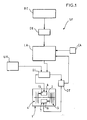
- FIG. 1 represents a block diagram of a braking system for a railway vehicle, comprising in particular the device with multiple disks of the invention.
- Figure 2 is a sectional view of an exemplary embodiment of the multiple disc braking device of the invention.
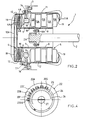
- Figure 3 is an axial section of one of the cylinders of the first pressure means, capable of acting against the two sets of discs depending on the state of a thermal safety member, said cylinder being in a inactive position.
- FIG. 4 partially represents an end view of said jack according to arrow F in FIG. 3.
- Figure 5 shows said cylinder illustrated in Figure 3 in the extended position of the piston acting against the metal discs.
- Figure 6 shows said cylinder illustrated in Figure 3, in the extended position of the intermediate jacket acting against the carbon discs, after the melting of said thermal member.
- the braking system SF shown diagrammatically in FIG. 1 comprises, in the application to a railway vehicle, an electric retarder RE to which are advantageously connected, for safety reasons, means for detecting a possible anomaly in its operation, such as a DE detector.
- the latter is associated with a control logic LA of the braking system, which controls, for example, an electro-hydraulic distributor DI, supplied with fluid by a hydraulic unit UH and connected to the braking device 1 with multiple disks of the invention.
- the purpose of the electric retarder RE when it is activated, is to slow the train down to an imposed limit speed VL, relatively low, from which, thanks to tripping means, such as a sensor of speed CA, connected to the servo logic LA, the braking device 1 is then requested, by the distributor DI, to brake the train until it stops.
- the braking device 1 shown in FIG. 2 is arranged between a rotary element to be braked, such as a shaft 2 mechanically and integrally connected to the wheels, and a fixed element, such as the structure 3 of the corresponding bogie .
- the device 1 comprises for example a first set of discs 4 made of a metallic material and a second set of discs 5 made of carbon, first and second pressure means 6 and 7 being capable of acting respectively on the first and second sets of discs 4 and 5.
- the second set of carbon discs 5 then remains inactive.
- the latter thanks to their structural characteristics, then ensure reliable and efficient braking of the train until it stops. It can also be provided that, as soon as the train has reached the speed limit VL thanks to the action of the carbon discs, the metal discs 4 come into action.
- the disks of said assemblies are defined by stators and rotors which, in this embodiment, are alternately connected to the rotary shaft 2 and to the fixed structure 3. More particularly, the first set of metal discs 4 comprises a rotor 4A and two stators 4B, while the second set of carbon discs 5 comprises two rotors 5A and three stators 5B. Also, the rotors 4A and 5A are mounted on the same hub 8 secured to the end 2A of the shaft 2 by screws 8A, said rotors usually being connected in rotation to the hub 8 and being able to slide axially relative to the latter by a conventional mounting with keys 9 provided on the hub.
- the stators 4B and 5B are mounted inside respective casings 10 and 11, said stators being fixed in rotation relative to the casings and being able to slide axially thanks to a mounting by keys 12 provided at the internal periphery of each casing. .
- the number of carbon or metal discs may be different.
- the only elements to be respected are, on the one hand, the total mass of the carbon or metallic disks taking into account their refractories, specific heats and respective kinetic energies to be absorbed and, on the other hand, the need to exert a total torque sufficient braking with all the discs of each kind, taking into account the forces exerted by the pressure means, the respective coefficients of friction and the number of discs of each kind.
- the rotor 4A is for example covered on its two faces with friction linings 4A 1 made of ceramic or differently and against which the stators 4B of metal are applied.
- the first 6 and second 7 pressure means are mounted on the same support 14 secured to the fixed structure 3 and consequently placed between the two sets of discs 4 and 5.
- These pressure means are usually constituted by two groups of jacks 15 and 16 capable of acting respectively against the first and second sets 4 and 5.
- the metal discs 4 are advantageously located on the external side of the end 2A of the rotary shaft, that is to say, in FIG. 2, to the left of the support 14.
- the casing 10, inside which these discs 4 are housed, is fixed, in this embodiment, by screws 17 to the support 14 and to the casing 11, while the latter, inside which the discs 5 are arranged, is then made integral with the fixed structure 3 of the bogie by screws 18.
- the jacks 15 and the jacks 16 of said pressure means are arranged alternately and equi-angularly distributed with respect to the support 14.
- the number of jacks 15 and 16 in each group can for example be between five and eight.
- cylinders 15 and 16 are associated, in known manner, with metal plates 19, as well as in the bottom 10A of the casing 10 and that in the open bottom 11A of the casing 11. In this way , when the jacks 15 or 16 act, the pressure plates 19, respectively arranged on either side of each set 4 and 5, press the stators and the rotors against each other.
- the first and second sets of discs 4 and 5 are each controlled by a group of jacks 15 or 16, it is possible, to increase the safety of the device 1, to use the jacks 15 of the first pressure means 6 to act advantageously on the second set of carbon discs 5, in particular in the event of a failure of the second pressure means 7 or of the hydraulic circuit supplying them.
- this failure can be detected by a detector DT provided on the hydraulic connection between the distributor DI and the second means 7 (FIG. 1), and connected to the control logic LA.
- each cylinder 15 is provided with an intermediate jacket 20 disposed between the piston 21, capable of acting against the metal discs 4 by the pressure plate 19, and the cylinder 22 which advantageously forms an integral part, in this embodiment, of the support 14.
- This jacket 20, having the shape of a piston is mounted head to tail on the piston 21, that is to say that its bottom 20A is then intended to be applied, as will be seen later, against the carbon discs 5.
- Rings 23 seal between the side wall 20B of the intermediate jacket 20 and the cylinder 22, as well as between this wall 20B and the piston 21.
- the jacks 15 are respectively equipped with thermal members or safety fuses 24 which, on the one hand, hold in position the intermediate liners 20 relative to the cylinders 22 when the braking of the train takes place normally, and on the other hand allows, through their fusion caused by overheating of the metal discs 4, the sliding of the liners 20 in the direction of the carbon discs 5 by means of the hydraulic pressure of the supply circuit.
- overheating can, for example, occur following a failure of the hydraulic circuit supplying the jacks 16 of the carbon discs 5 which must be actuated during a breakdown of the retarder.
- the failure is signaled by the detector DT, connected to the operating logic LA of the braking system SF, which cancels the control of the cylinders 15 of the metal discs at the imposed speed limit VL to authorize it to operate at beyond this speed.
- the metal discs 4 quickly reach high temperatures which cause the thermal safety members 24 to merge and, consequently, the action of the intermediate liners 20 on the carbon discs 5 then authorizing the stopping of the train.
- each member 24 is constituted by a split ring made of a material whose melting point corresponds to a determined temperature of overheating of the discs 4, for which it is desired that the braking of the carbon discs 5 by the jacks 15 takes place, in the event of a malfunction of the hydraulic circuit of the carbon discs.
- the ring 24 can be made of light alloy.
- the ring 24 is engaged in an internal peripheral groove 20D, provided in the side wall 20B of the jacket, in the vicinity of its end 20E opposite the bottom, and it projects from the groove 20D to be applied, thanks to its intrinsic elasticity, against and around an envelope 25 surrounding the front part 21A of the piston 21, which is delimited by a shoulder 21B.
- This envelope 25 which has the shape of a hollow piston, is made of a heat-conducting material such as copper, so that the action of the metal discs during braking results in an increase in the temperature of the casing 25 and therefore of the split ring 24 which presses around.
- the two casings 25 and 26 superimposed are fixed to the front part 21A of the piston by a screw 27 as shown in FIGS. 3 and 4.
- the intermediate jacket 20 is held axially in position relative to the cylinder 22.
- the displacement of the jacket 20 towards the metal discs 4 is made impossible due to a fitting connection. between the jacket 20 and the cylinder 22.
- the latter is provided with a crenellated transverse rim 22A, engaging and passing through the end 20E of the liner, which is also crenellated.
- the teeth 22B of the rim cross the spaces 20F of the crenellated end 20E of the shirt and they come flush with the envelope 25; conversely, the spaces 22C of said flange 22A receive the teeth 20G from the end 20E of the jacket.
- the displacement of the latter towards the carbon discs 5 is made impossible by the thermal ring 24 linked to the jacket and pressing against the crenellated edge 22A of the fixed cylinder 22.
- the establishment of the split thermal ring 24 is possible by dismantling the casing 25 and reducing the diameter of the ring 24 thanks to its circumferential play, which allows it to be engaged in the internal peripheral groove 20D when all the other parts are in the position of figure 3.
- the production of the first pressure means in the form of two-piston cylinders makes it possible to guarantee the braking of the rail vehicle following a failure of the second pressure means.
- the cylinders 15 of the braking device operate in the following manner.
- the jacks 15 act on the metal discs 4 from the imposed limit speed VL delivered by the sensor CA, for which the retarder becomes ineffective.
- the hydraulic fluid passes through the passages 20C of the liners and pushes all the pistons 21 to the left which, via the pressure plates 19, cause the friction of the metal discs 4 until the train stops.
- the carbon discs 5 under the action of the jacks 16 then advantageously ensure braking and stopping of the rail vehicle.
- the detector DT detects the failure of the second pressure means on the circuit supplying them, and the servo logic LA, to which the detector is connected, removes the control condition of the first pressure means, that is to say that is to say cylinders 15, from the imposed speed limit threshold VL coming from the sensor CA.
- the jacks 15 are supplied by the distributor DI and the pistons 21 move to act on the metal discs, as shown in Figure 5. Due to the high amount of energy to be absorbed to stop the train can traveling at a high speed, the linings 4A 1 of the discs 4 wear and rise very quickly in temperature until reaching a determined superheating temperature, corresponding to the melting temperature of the rings 24, and transmitted by the envelopes 25. Thus , under the action of the hydraulic pressure exerted both on the piston 21 and on the bottom 20A of the liners 20, the latter then slide in the direction of the carbon disks 5 since the rings have melted.
- FIG. 6 shows the position occupied then by each jack 15 in an extreme case where the piston 21 is in abutment by the shoulder 21B against the crenellated rim 22A of the cylinder, while the jacket 20 is in the maximum extended position.
- the pistons 21 of the cylinders are preferably hollow making it possible to house, in a known manner, return springs not shown.
- the braking device can continue to operate with the carbon discs 5. It is noted that, thanks to the arrangement of the metal discs on the external side of the shaft 2, the replacement of the discs 4 and of the thermal rings 24 of the jacks 15 is particularly easy by removing for this purpose the casing 10, which is very accessible.
Landscapes
- Engineering & Computer Science (AREA)
- Mechanical Engineering (AREA)
- General Engineering & Computer Science (AREA)
- Transportation (AREA)
- Braking Arrangements (AREA)
- Valves And Accessory Devices For Braking Systems (AREA)
Applications Claiming Priority (2)
| Application Number | Priority Date | Filing Date | Title |
|---|---|---|---|
| FR9104849 | 1991-04-19 | ||
| FR9104849A FR2675450B1 (fr) | 1991-04-19 | 1991-04-19 | Dispositif de freinage a disques multiples. |
Publications (2)
| Publication Number | Publication Date |
|---|---|
| EP0509879A1 true EP0509879A1 (de) | 1992-10-21 |
| EP0509879B1 EP0509879B1 (de) | 1994-12-14 |
Family
ID=9412049
Family Applications (1)
| Application Number | Title | Priority Date | Filing Date |
|---|---|---|---|
| EP92400979A Expired - Lifetime EP0509879B1 (de) | 1991-04-19 | 1992-04-08 | Lamellenscheibenbremsanlage |
Country Status (7)
| Country | Link |
|---|---|
| US (1) | US5293966A (de) |
| EP (1) | EP0509879B1 (de) |
| JP (1) | JP3259977B2 (de) |
| AT (1) | ATE115476T1 (de) |
| CA (1) | CA2066347C (de) |
| DE (1) | DE69200884T2 (de) |
| FR (1) | FR2675450B1 (de) |
Families Citing this family (28)
| Publication number | Priority date | Publication date | Assignee | Title |
|---|---|---|---|---|
| JPS58147106A (ja) * | 1982-02-26 | 1983-09-01 | Toshiba Corp | 鉄心材料 |
| US5817979A (en) * | 1995-01-17 | 1998-10-06 | Thomas & Betts Corporation | Bond bar for an electrical cable splice |
| DE19703688B4 (de) * | 1997-01-31 | 2006-02-09 | Robert Bosch Gmbh | Verfahren und Vorrichtung zur Steuerung einer Bremsanlage |
| US6503271B2 (en) * | 1998-01-09 | 2003-01-07 | Cordis Corporation | Intravascular device with improved radiopacity |
| US6062657A (en) * | 1998-04-21 | 2000-05-16 | Daimlerchrysler Rail Systems (North America) Inc. | Brake failure compensation system and method |
| DE19859617C1 (de) * | 1998-12-23 | 2000-05-25 | Daimler Chrysler Ag | Verfahren zur Betätigung einer Bremseinheit |
| NL1011142C2 (nl) * | 1999-01-27 | 2000-07-31 | Skf Eng & Res Centre Bv | Compacte actuator. |
| US6530625B2 (en) | 1999-08-27 | 2003-03-11 | Alliedsignal Inc. | Electrically actuated brake with vibration damping |
| JP3872242B2 (ja) * | 1999-09-21 | 2007-01-24 | トヨタ自動車株式会社 | ブレーキ制御装置 |
| DE10000915C2 (de) * | 2000-01-12 | 2002-11-07 | Daimler Chrysler Ag | Bremsvorrichtung für ein Fahrzeug |
| US20040262105A1 (en) * | 2003-05-13 | 2004-12-30 | Zhesheng Li | Eddy-current wheelend retarder featuring modified rotor skin effect |
| US20100025167A1 (en) * | 2008-07-31 | 2010-02-04 | Caterpillar Inc. | Braking system for an off-highway machine involving electric retarding integrated with service brakes |
| US8281908B2 (en) | 2008-08-29 | 2012-10-09 | Caterpillar Inc. | Brake cooling fluid diverter for an off-highway machine |
| US9063202B2 (en) * | 2008-09-15 | 2015-06-23 | Caterpillar Inc. | Method and apparatus for detecting phase current imbalance in a power generator |
| US8140206B2 (en) | 2008-09-15 | 2012-03-20 | Caterpillar Inc. | Engine load management for traction vehicles |
| US8054016B2 (en) | 2008-09-15 | 2011-11-08 | Caterpillar Inc. | Retarding energy calculator for an electric drive machine |
| US20100065356A1 (en) * | 2008-09-15 | 2010-03-18 | Caterpillar Inc. | Electric powertrain for off-highway trucks |
| US7918296B2 (en) * | 2008-09-15 | 2011-04-05 | Caterpillar Inc. | Cooling system for an electric drive machine and method |
| US8324846B2 (en) * | 2008-09-15 | 2012-12-04 | Caterpillar Inc. | Electric drive retarding system and method |
| US7996163B2 (en) * | 2008-09-15 | 2011-08-09 | Caterpillar Inc. | Method and apparatus for detecting a short circuit in a DC link |
| US8410739B2 (en) * | 2008-09-15 | 2013-04-02 | Caterpillar Inc. | Method and apparatus for determining the operating condition of generator rotating diodes |
| US7795825B2 (en) | 2008-09-15 | 2010-09-14 | Caterpillar Inc | Over-voltage and under-voltage management for electric drive system |
| US7956762B2 (en) | 2008-09-15 | 2011-06-07 | Caterpillar Inc. | Method and apparatus for power generation failure diagnostics |
| US8253357B2 (en) * | 2008-09-15 | 2012-08-28 | Caterpillar Inc. | Load demand and power generation balancing in direct series electric drive system |
| FR2942305B1 (fr) * | 2009-02-17 | 2011-02-18 | Cooltech Applications | Generateur thermique magnetocalorique |
| US8626368B2 (en) | 2010-09-07 | 2014-01-07 | Caterpillar Inc. | Electric drive power response management system and method |
| CN109070739B (zh) | 2016-02-18 | 2021-08-31 | 双环公司 | 用于工业驱动器的带有多力制动器系统的液压动力输出 |
| JP6648670B2 (ja) * | 2016-11-02 | 2020-02-14 | トヨタ自動車株式会社 | 電動ブレーキアクチュエータ |
Citations (5)
| Publication number | Priority date | Publication date | Assignee | Title |
|---|---|---|---|---|
| GB679667A (en) * | 1949-03-03 | 1952-09-24 | Bendix Aviat Corp | Improvements in or relating to wheel and brake assemblies |
| DE2026478A1 (de) * | 1969-06-18 | 1970-12-23 | The Bendix Corp., Southfield, Mich. (V.St.A,) | Wärmeabschirmung für die Nachstellvorrichtung einer Innenbacken-Trommelbremse |
| DE2812643A1 (de) * | 1977-03-28 | 1978-10-12 | Montalvo Sen | Vorrichtung zum reibschluessigen kuppeln zweier gegeneinander drehbarer koerper |
| GB2197924A (en) * | 1986-11-28 | 1988-06-02 | Iveco Fiat | Decelerator device |
| US5072811A (en) * | 1989-12-27 | 1991-12-17 | Aircraft Braking Systems Corporation | Telescopic brake piston |
Family Cites Families (10)
| Publication number | Priority date | Publication date | Assignee | Title |
|---|---|---|---|---|
| US3951240A (en) * | 1971-10-07 | 1976-04-20 | Dunlop Limited | Frictional disc arrangement for a disc brake |
| FR2221978A5 (de) * | 1973-03-15 | 1974-10-11 | Ferodo Sa | |
| DE2745283A1 (de) * | 1977-10-07 | 1979-04-12 | Knorr Bremse Gmbh | Scheibenbremseinrichtung |
| US4207968A (en) * | 1978-02-21 | 1980-06-17 | Caterpillar Tractor Co. | Double disc type brake system |
| US4671577A (en) * | 1985-11-21 | 1987-06-09 | Urban Transportation Development Corporation Ltd. | Combined regenerative and friction braking system for a vehicle |
| FR2624232B1 (fr) * | 1987-12-04 | 1991-11-22 | Elf France | Dispositif de freinage d'un element rotatif |
| US4923056A (en) * | 1989-02-21 | 1990-05-08 | Aircraft Braking Systems Corporation | Method of increasing the service life of aircraft carbon disk brakes |
| US4986610A (en) * | 1989-02-21 | 1991-01-22 | Aircraft Braking Systems Corporation | Brake system with brake selection means |
| DE4024078A1 (de) * | 1990-07-28 | 1992-01-30 | Bosch Gmbh Robert | Verfahren zum betreiben der bremsanlage eines nutzfahrzeugs |
| FR2672559B1 (fr) * | 1991-02-12 | 1993-05-28 | Aerospatiale | Systeme de freinage pour vehicule a roues. |
-
1991
- 1991-04-19 FR FR9104849A patent/FR2675450B1/fr not_active Expired - Fee Related
-
1992
- 1992-04-08 EP EP92400979A patent/EP0509879B1/de not_active Expired - Lifetime
- 1992-04-08 AT AT92400979T patent/ATE115476T1/de not_active IP Right Cessation
- 1992-04-08 DE DE69200884T patent/DE69200884T2/de not_active Expired - Fee Related
- 1992-04-15 JP JP09527892A patent/JP3259977B2/ja not_active Expired - Fee Related
- 1992-04-16 CA CA002066347A patent/CA2066347C/fr not_active Expired - Fee Related
-
1993
- 1993-07-16 US US08/093,459 patent/US5293966A/en not_active Expired - Lifetime
Patent Citations (5)
| Publication number | Priority date | Publication date | Assignee | Title |
|---|---|---|---|---|
| GB679667A (en) * | 1949-03-03 | 1952-09-24 | Bendix Aviat Corp | Improvements in or relating to wheel and brake assemblies |
| DE2026478A1 (de) * | 1969-06-18 | 1970-12-23 | The Bendix Corp., Southfield, Mich. (V.St.A,) | Wärmeabschirmung für die Nachstellvorrichtung einer Innenbacken-Trommelbremse |
| DE2812643A1 (de) * | 1977-03-28 | 1978-10-12 | Montalvo Sen | Vorrichtung zum reibschluessigen kuppeln zweier gegeneinander drehbarer koerper |
| GB2197924A (en) * | 1986-11-28 | 1988-06-02 | Iveco Fiat | Decelerator device |
| US5072811A (en) * | 1989-12-27 | 1991-12-17 | Aircraft Braking Systems Corporation | Telescopic brake piston |
Also Published As
| Publication number | Publication date |
|---|---|
| DE69200884D1 (de) | 1995-01-26 |
| EP0509879B1 (de) | 1994-12-14 |
| FR2675450A1 (fr) | 1992-10-23 |
| ATE115476T1 (de) | 1994-12-15 |
| CA2066347C (fr) | 1999-12-21 |
| JP3259977B2 (ja) | 2002-02-25 |
| FR2675450B1 (fr) | 1993-08-06 |
| US5293966A (en) | 1994-03-15 |
| CA2066347A1 (fr) | 1992-10-20 |
| DE69200884T2 (de) | 1995-05-04 |
| JPH05112235A (ja) | 1993-05-07 |
Similar Documents
| Publication | Publication Date | Title |
|---|---|---|
| EP0509879B1 (de) | Lamellenscheibenbremsanlage | |
| EP0509880B1 (de) | Mehrscheibenbremse für ein Rad | |
| EP3090190B1 (de) | Aktuator mit irreversiblem gewinde, trommelbremsaktuator und bremsvorrichtung mit so einem aktuator | |
| EP0291429B1 (de) | Scheibe für Scheibenbremse | |
| EP3089898B1 (de) | Trommelbremse mit feststellbremse in doppelservomodos betrieben, fahrzeug mit so einer bremse, und -herstellungsverfahren | |
| EP0235035B1 (de) | Bremssteuereinheit mit Antriebsfeder und ihre Anwendung in einer Bremsvorrichtung | |
| FR3016011A1 (fr) | Actionneur entraine par pignon a glissiere axiale, et frein a tambour et dispositif de freinage ainsi equipes | |
| EP0346195A1 (de) | Elektromagnetische Bremse mit Klemmbacke | |
| EP0483719B1 (de) | Bremsanlage für Schienenfahrzeuge | |
| EP0595691B1 (de) | Bremsvorrichtung für Schienenfahrzeuge unter Verwendung von Kohlenstoff enthaltendem Material | |
| EP0366509B1 (de) | Bremse mit zwei Scheiben mit festem Abstand | |
| FR2607566A1 (fr) | Dispositif decelerateur pour des vehicules industriels | |
| EP0039641B1 (de) | Punktuell angreifende Bremse | |
| EP0081586B1 (de) | Asynchroner elektrischer bremsmotor mit kurzschlussrotor und doppelter wirkung | |
| FR2465923A1 (fr) | Frein d'urgence | |
| FR3097605A1 (fr) | Etrier de frein à double actionneur, frein à disque et procédé de freinage associés | |
| FR2514091A1 (fr) | Moyeu de roue | |
| CA1131567A (fr) | Frein a expansion axiale | |
| EP1649187B1 (de) | Feststellbremse mit verbesserter starrheit | |
| FR2517002A1 (fr) | Frein a manque d'energie, et moyeu de roue comportant un tel frein | |
| FR3132684A1 (fr) | Systeme pour augmenter la pression d’intervention d’un frein | |
| FR2586769A1 (fr) | Embrayage a commande hydraulique. | |
| FR2540478A1 (fr) | Groupe moto-reducteur a frein automatique, notamment pour engin de manutention | |
| EP1339998A1 (de) | Scheibenbremse, insbesondere für industriegebrauch | |
| BE628341A (de) |
Legal Events
| Date | Code | Title | Description |
|---|---|---|---|
| PUAI | Public reference made under article 153(3) epc to a published international application that has entered the european phase |
Free format text: ORIGINAL CODE: 0009012 |
|
| AK | Designated contracting states |
Kind code of ref document: A1 Designated state(s): AT BE CH DE ES GB GR IT LI LU NL PT SE |
|
| 17P | Request for examination filed |
Effective date: 19921123 |
|
| 17Q | First examination report despatched |
Effective date: 19940307 |
|
| GRAA | (expected) grant |
Free format text: ORIGINAL CODE: 0009210 |
|
| AK | Designated contracting states |
Kind code of ref document: B1 Designated state(s): AT BE CH DE ES GB GR IT LI LU NL PT SE |
|
| PG25 | Lapsed in a contracting state [announced via postgrant information from national office to epo] |
Ref country code: NL Effective date: 19941214 Ref country code: GR Free format text: LAPSE BECAUSE OF FAILURE TO SUBMIT A TRANSLATION OF THE DESCRIPTION OR TO PAY THE FEE WITHIN THE PRESCRIBED TIME-LIMIT Effective date: 19941214 Ref country code: ES Free format text: THE PATENT HAS BEEN ANNULLED BY A DECISION OF A NATIONAL AUTHORITY Effective date: 19941214 Ref country code: AT Effective date: 19941214 |
|
| REF | Corresponds to: |
Ref document number: 115476 Country of ref document: AT Date of ref document: 19941215 Kind code of ref document: T |
|
| REF | Corresponds to: |
Ref document number: 69200884 Country of ref document: DE Date of ref document: 19950126 |
|
| GBT | Gb: translation of ep patent filed (gb section 77(6)(a)/1977) |
Effective date: 19950111 |
|
| ITF | It: translation for a ep patent filed | ||
| PG25 | Lapsed in a contracting state [announced via postgrant information from national office to epo] |
Ref country code: SE Effective date: 19950314 Ref country code: PT Effective date: 19950314 |
|
| PG25 | Lapsed in a contracting state [announced via postgrant information from national office to epo] |
Ref country code: LU Free format text: LAPSE BECAUSE OF NON-PAYMENT OF DUE FEES Effective date: 19950430 Ref country code: BE Effective date: 19950430 |
|
| NLV1 | Nl: lapsed or annulled due to failure to fulfill the requirements of art. 29p and 29m of the patents act | ||
| PLBE | No opposition filed within time limit |
Free format text: ORIGINAL CODE: 0009261 |
|
| STAA | Information on the status of an ep patent application or granted ep patent |
Free format text: STATUS: NO OPPOSITION FILED WITHIN TIME LIMIT |
|
| BERE | Be: lapsed |
Owner name: AEROSPATIALE SOC. NATIONALE INDUSTRIELLE Effective date: 19950430 |
|
| 26N | No opposition filed | ||
| REG | Reference to a national code |
Ref country code: GB Ref legal event code: IF02 |
|
| PGFP | Annual fee paid to national office [announced via postgrant information from national office to epo] |
Ref country code: CH Payment date: 20020402 Year of fee payment: 11 |
|
| PGFP | Annual fee paid to national office [announced via postgrant information from national office to epo] |
Ref country code: GB Payment date: 20020410 Year of fee payment: 11 |
|
| PGFP | Annual fee paid to national office [announced via postgrant information from national office to epo] |
Ref country code: DE Payment date: 20020430 Year of fee payment: 11 |
|
| PG25 | Lapsed in a contracting state [announced via postgrant information from national office to epo] |
Ref country code: GB Free format text: LAPSE BECAUSE OF NON-PAYMENT OF DUE FEES Effective date: 20030408 |
|
| PG25 | Lapsed in a contracting state [announced via postgrant information from national office to epo] |
Ref country code: LI Free format text: LAPSE BECAUSE OF NON-PAYMENT OF DUE FEES Effective date: 20030430 Ref country code: CH Free format text: LAPSE BECAUSE OF NON-PAYMENT OF DUE FEES Effective date: 20030430 |
|
| PG25 | Lapsed in a contracting state [announced via postgrant information from national office to epo] |
Ref country code: DE Free format text: LAPSE BECAUSE OF NON-PAYMENT OF DUE FEES Effective date: 20031101 |
|
| GBPC | Gb: european patent ceased through non-payment of renewal fee |
Effective date: 20030408 |
|
| REG | Reference to a national code |
Ref country code: CH Ref legal event code: PL |
|
| PG25 | Lapsed in a contracting state [announced via postgrant information from national office to epo] |
Ref country code: IT Free format text: LAPSE BECAUSE OF NON-PAYMENT OF DUE FEES;WARNING: LAPSES OF ITALIAN PATENTS WITH EFFECTIVE DATE BEFORE 2007 MAY HAVE OCCURRED AT ANY TIME BEFORE 2007. THE CORRECT EFFECTIVE DATE MAY BE DIFFERENT FROM THE ONE RECORDED. Effective date: 20050408 |