EP0509564B1 - Ofen für die Herstellung von Vorformen für optische Faser - Google Patents
Ofen für die Herstellung von Vorformen für optische Faser Download PDFInfo
- Publication number
- EP0509564B1 EP0509564B1 EP92112265A EP92112265A EP0509564B1 EP 0509564 B1 EP0509564 B1 EP 0509564B1 EP 92112265 A EP92112265 A EP 92112265A EP 92112265 A EP92112265 A EP 92112265A EP 0509564 B1 EP0509564 B1 EP 0509564B1
- Authority
- EP
- European Patent Office
- Prior art keywords
- muffle tube
- preform
- furnace
- carbon
- highly pure
- Prior art date
- Legal status (The legal status is an assumption and is not a legal conclusion. Google has not performed a legal analysis and makes no representation as to the accuracy of the status listed.)
- Expired - Lifetime
Links
Images
Classifications
-
- C—CHEMISTRY; METALLURGY
- C03—GLASS; MINERAL OR SLAG WOOL
- C03B—MANUFACTURE, SHAPING, OR SUPPLEMENTARY PROCESSES
- C03B5/00—Melting in furnaces; Furnaces so far as specially adapted for glass manufacture
-
- C—CHEMISTRY; METALLURGY
- C03—GLASS; MINERAL OR SLAG WOOL
- C03B—MANUFACTURE, SHAPING, OR SUPPLEMENTARY PROCESSES
- C03B37/00—Manufacture or treatment of flakes, fibres, or filaments from softened glass, minerals, or slags
- C03B37/01—Manufacture of glass fibres or filaments
- C03B37/012—Manufacture of preforms for drawing fibres or filaments
- C03B37/014—Manufacture of preforms for drawing fibres or filaments made entirely or partially by chemical means, e.g. vapour phase deposition of bulk porous glass either by outside vapour deposition [OVD], or by outside vapour phase oxidation [OVPO] or by vapour axial deposition [VAD]
- C03B37/01446—Thermal after-treatment of preforms, e.g. dehydrating, consolidating, sintering
- C03B37/0146—Furnaces therefor, e.g. muffle tubes, furnace linings
-
- C—CHEMISTRY; METALLURGY
- C03—GLASS; MINERAL OR SLAG WOOL
- C03B—MANUFACTURE, SHAPING, OR SUPPLEMENTARY PROCESSES
- C03B2201/00—Type of glass produced
- C03B2201/06—Doped silica-based glasses
- C03B2201/08—Doped silica-based glasses doped with boron or fluorine or other refractive index decreasing dopant
- C03B2201/12—Doped silica-based glasses doped with boron or fluorine or other refractive index decreasing dopant doped with fluorine
Definitions
- the present invention relates to a furnace in which a porous glass preform for an optical fiber preform is thermally treated, for example, dehydrated, doped or sintered to produce a highly pure quartz glass preform for an optical fiber.
- a porous glass preform consisting of fine quartz glass particles produced by the Vapor Phase Axial Deposition or the Outside Chemical Vapor Deposition is dehydrated, densified and vitrified. During the dehydration, the densification and/or the vitrification, fluorine is added to the glass to control a refractive index profile of the preform.
- a heating furnace comprising a muffle tube is used for the dehydration, the densification or the vitrification.
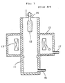
- FIG. 1 One example of such a heating furnace comprising a muffle tube is shown in Fig. 1.
- the conventional heating furnace comprises a hollow furnace body 12 and a muffle tube 11 which passes through the furnace body 12.
- a heating member 13 is placed in the furnace body 12 which has an inlet 17 for introducing an inert gas into the furnace body in order to prevent deterioration of the muffle tube, and the muffle tube 11 has an inlet 16 for introducing an atmosphere gas such as Cl2, SiF4 or He into the muffle tube.
- a porous preform 15 is thermally treated by means of the heater 13 while it is suspended from a supporting rod 14.
- the muffle tube is made of highly pure carbon coated with silicon carbide (hereinafter referred to as SiC).
- a carbon made muffle tube coated with SiC is used, and a surface of the SiC coating is further oxidized.
- Such a muffle tube comprises carbon as a substrate, it can be kept at a high temperature without deterioration, whereby it can be heated and cooled many times with careful temperature change.
- the carbon substrate is hardly oxidized since it is coated with SiC so that impurities contained in the carbon substrate do not penetrate the glass preform. Because the surface of the SiC coating has been oxidized, the muffle tube does not deteriorate with Cl2 or SiF4.
- the conventional muffle tube comprises the carbon made substrate, a surface of which is coated with SiC and the surface of the SiC coating is oxidized.
- the oxidation of the SiC coating is carried out in an atmosphere comprising oxygen during the dehydration or the fluorine addition of the glass preform.
- the muffle tube is baked in an oxygen atmosphere. If the SiC coating partially peels off, the carbon made substrate of the muffle tube is severely oxidized during the oxidation step of the SiC coating, whereby the life of the muffle tube is extremely reduced.
- the SiC coating is rapidly deteriorated by the fluorine-containing gas when the oxidation of the SiC coating is omitted. Such deterioration begins at a temperature of 1200 °C with SiF4 gas, and rapidly proceeds at a temperature above 1400 °C. As a result, the carbon made substrate under the SiC coating is oxidized by a small amount of oxygen, whereby the life of the muffle tube is extremely shortened.
- the glass preform may be densified/vitrified in an atmosphere consisting of an inert gas, depending on the kind of optical fiber which is drawn from the preform.
- the surface of the SiC coating is not required to be oxidized for the protection from Cl2 or SiF4, and then it is more preferable to omit the oxidation step since sensitive conditions are required.
- the SiC coating may be oxidized with a small amount of oxygen in the muffle tube.
- EP-A-0 302 121 discloses a heating furnace for heating a porous preform made of fine particles of quartz base glass for an optical fiber in an atmosphere comprising a fluorine-containing atmosphere to add fluorine to the preform and to vitrify the preform to produce a glass preform for an optical fiber, which comprises a heater and muffle tube positioned inside the heater to separate a heating atmosphere from the heater, wherein at least the inner layer of the muffle tube consists of highly pure carbon.
- the muffle tube comprises an inner layer made of highly pure carbon and an outer layer made of silicon carbide.
- the muffle tube comprises a tube body made of silicon carbide and a layer of highly pure carbon coated on an inner wall of the tube body.
- a furnace comprising a muffle tube made of a gas impermeable and heat resistant material, a heater in a furnace body which surrounds the muffle tube and an inner cylinder made of a heat resistant material which is detachably fitted inside the muffle tube near the heater for a thermal treatment of a quartz glass preform by inserting the preform in the muffle tube
- said muffle tube comprises a material selected from a group consisting of highly pure carbon coated with gas impermeable silicon carbide, sintered silicon carbide coated with gas impermeable silicon carbide, gas impermeable silicon carbide and highly pure carbon coated with gas impermeable carbon
- said inner cylinder comprises a material selected from a group consisting of highly pure carbon, highly pure carbon coated with gas impermeable silicon carbide and highly pure carbon coated with gas impermeable carbon.
- the porous glass preform made of quartz is thermally treated with the heater in the muffle tube in the furnace body. During such treatment, a small amount of oxygen and/or water in the muffle tube firstly reacts with a material of the inner cylinder which is fitted inside the muffle tube and near the heater. Therefore, the water and the oxygen do not directly react with the muffle tube to deteriorate it.
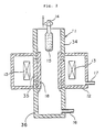
- an inner cylinder 18 is detachably fitted inside a muffle tube 11 near a heater 13.
- the muffle tube 11 is made of highly pure carbon coated with gas impermeable SiC.
- the muffle tube may be made of sintered silicon carbide coated with gas impermeable SiC, gas impermeable SiC or highly pure carbon coated with gas impermeable carbon such as pyrolitic carbon or vitreous carbon.
- gas impermeable carbon such as pyrolitic carbon or vitreous carbon.
- the SiC or the carbon coating is applied, at least an inner surface of the muffle tube is coated with SiC or carbon. Both surfaces, of course, may be coated with SiC or carbon.
- the inner cylinder 18 is made of highly pure carbon in this embodiment, at least an inner surface of the inner cylinder may be coated with gas impermeable carbon or SiC.
- the porous glass preform 15 is thermally treated, for example, dehydrated, fluorine-added and/or sintered with the heater 13 in an atmosphere comprising a gas such as SiCl4, SiF4 or He supplied through an inlet 16 in the muffle tube 11. During the treatment, a trace amount of oxygen and water adsorbed in the quartz made porous glass preform 15 is liberated into the atmosphere in the muffle tube 11.
- a gas such as SiCl4, SiF4 or He supplied through an inlet 16 in the muffle tube 11.
- the following reaction proceeds to deteriorate the SiC coating: SiC + 3SiF4 + 1/2O2 ⁇ 4SiF3 + CO (1)
- the surface of the SiC coating is oxidized with oxygen in the muffle tube according to the following equation: 2SiC + 3O2 ⁇ 2SiO2 + 2CO (2) and the SiC coating may be destroyed in the worst case.
- the deterioration does not reach the muffle tube and the muffle tube is protected.
- the atmosphere gas cannot penetrate the inner cylinder 18 itself during the initial term of use, whereby the protection with the inner cylinder 18 for the SiC coating on the muffle tube 11 is further promoted.
- the inner cylinder is installed so that it covers a portion of an inner surface of the muffle tube near the heater 13 which is heated to a temperature above 1200 °C.
- the inner cylinder 18 gradually wears according to the equation (3) during each thermal treatment of the porous preform 15. With such wear, the muffle tube 11 and the SiC coating thereon is fully protected by means of the inner cylinder 18. Although the inner cylinder has to be replaced with a new one depending on the extent of wear, cost reduction over replacement of the muffle tube can be realized since the inner cylinder 18 is smaller and easily fabricated in comparison with the muffle tube 11.
- Quartz made porous glass preforms 15 were thermally treated with using the conventional furnace as shown in Fig. 1 and the present furnace as shown in Fig. 2. Then, pure silica core single mode optical fibers were drawn from the treated preforms.
- the muffle tube 11 used in each furnace was made of highly pure carbon coated with SiC, and the inner cylinder 18 was made of highly pure carbon. Temperature conditions and atmosphere gas conditions of the treatments are shown in following Table 1: Table 1 Treatment Temperature Atmosphere gas Dehydration 950-1100 °C SiCl4, He F-addition 1250-1400 °C SiF4, He Sintering 1550-1650 °C He
- the pure silica single mode optical fiber drawn from the thermally treated preform with the present furnace had a very low average transmission loss of 0.173 dB/km at a wavelength of 1.55 ⁇ m.
- the glass preform was thermally treated using the present furnace comprising the inner tube made of highly pure carbon
- air may enter the muffle tube when the porous glass preform 15 is inserted in the inner tube, whereby the inner tube may be deteriorated due to oxidation.
- the insertion of the glass preform may be performed at a temperature below 400 °C or an upper portion of the muffle tube 11 may be partitioned as a front chamber.
- the present furnace for the production of the highly pure quartz preform by the thermal treatment a small amount of oxygen and water contained in the glass preform firstly reacts with the inner cylinder during the thermal treatment of the preform since the inner cylinder is detachably fitted inside the muffle tube. Therefore, oxygen and water do not directly deteriorate the muffle tube, whereby the life of the muffle tube is extended and the preform is suitably thermally treated.
- a furnace as described above, wherein at least one highly pure carbon-made member which constitutes the muffle tube or the inner cylinder, or optional additional element in the muffle tube which is necessary for the muffle tube (for example, a part of a supporting rod) is made of a graphite material selected from the group consisting of a graphite material which is produced by self-sintering mesophase powder and a highly pure graphite material consisting of raw particles selected from the group consisting of particles having a maximum particle size of not larger than 50 ⁇ m and particles having an average particle size of not larger than 20 ⁇ m.
- the muffle tube may comprise a single highly pure carbon-made member or a plurality of the highly pure carbon-made members.
- the member may be made of either of the graphite materials as described above.
- the muffle tube consists of a plurality of the highly pure carbon made members, at least one member which is heated to the highest temperature (for example 1200 °C) is preferably made of either of the graphite materials as described above. All of the members may be made of such graphite materials.
- any member may be provided with the gas impermeable coating made of, for example, SiC, pyrolitic carbon or vitreous carbon, it is preferable to provide at least the member which is heated to such highest temperature with the coating.
- the inner tube and optional element which is, hereinafter, also referred to as muffle tube assembly
- muffle tube assembly at least a part of which is made of the graphite material produced by self-sintering the mesophase powder
- graphite material produced by self-sintering the mesophase powder is intended to mean a graphite material produced by self-sintering an intermediate liquid phase in which fine spherical particles having optical anisotropy are generated during an initial period of a thermal treatment of coal or heavy oil. Such particles are called mesophase fine spherical particles.
- the graphite material which is produced by self-sintering the mesophase powder is commercially available from Sumitomo Metal Industries, Ltd. (Osaka, Japan) and Toshiba Ceramics Co., Ltd. (Tokyo, Japan).
- the quartz glass preform is thermally treated in the present furnace having the muffle tube assembly comprising (at least one member made of) the highly pure graphite material consisting of the raw particles having a maximum particle size (diameter) of not larger than 50 ⁇ m or an average particle size (diameter) of not larger than 20 ⁇ m
- generation of carbon powder is hardly observed.
- graphite powder is so fine that it reacts with SiO2 on the preform surface to produce gases of SiO and CO, whereby no bubble is generated because of the absence of the carbon powder in the preform.
- the furnace of the preferred embodiment of the second aspect of the present invention is schematically shown also in Fig. 2 as a sectional view.
- the muffle tube 11 comprises three members, that is the upper member 34, the middle member 35 and the lower member 36, and the inner cylinder 18 which is made of the graphite material produced by self-sintering the mesophase powder.
- the inner cylinder may be provided with the gas impermeable coating (not shown).
- the middle member 35 is preferably made of the graphite material produced by self-sintering the mesophase powder provided with the gas impermeable coating (not shown).
- the middle member 35 is not necessarily made of the graphite material produced by self-sintering the mesophase powder.
- Other members such as the upper member and the lower member may be optionally made of such graphite material and may be provided with the gas impermeable coating.
- the inner cylinder may be made of the highly pure graphite material consisting of the raw particles having a maximum particle size of not larger than 50 ⁇ m or an average particle size of not larger than 20 ⁇ m.
- the middle member 35 is also preferably made of the highly pure graphite material coated with the gas impermeable layer as described above.
- the middle member 35 is not necessarily made of such highly pure graphite material.
- Other members such as the upper member and the lower member may be optionally made of such graphite material and provided with the gas impermeable coating.
- the furnace as shown in Fig. 2 was used.
- the inner cylinder 18 was made of the graphite material produced by self-sintering the mesophase powder.
- a bulk specific gravity of the graphite material was 1.95 and a maximum size of the raw particles for the graphite material was 5 ⁇ m.
- the middle member 35 of the muffle tube 3 was made of a usual isotropical graphite and was coated with the gas impermeable pyrolysis carbon.
- the upper and lower members 34 and 36 were made of usual isotropical graphite and were coated with the gas impermeable SiC.
- An optical fiber was drawn from each of the tenth and the eightieth preforms. Twenty sample fibers each having a length of 20 m were cut from each optical fiber and they were tested for longitudinal tensile strength. There was no sample fiber which had low strength, that is, a tensile strength of less than 44 N (4.5 kg-f).
- Example 1 was repeated except that a furnace which comprised an inner cylinder made of a usual isotropical carbon material was used.
- the carbon material had a bulk specific gravity of 1.77 and a maximum raw particle size of 60 ⁇ m.
- Sixty preforms were sintered under the same conditions as in Example 1.
- the furnace of the present invention having the muffle tube assembly at least a part of which is made of the graphite material produced by self-sintering the mesophase powder can be used to thermally treat the preform for a long period without the generation of carbon powder in the muffle tube and without strength reduction of the optical fiber drawn from the preform.
- the furnace as shown in Fig. 2 was used.
- the inner cylinder 8 was made of the graphite material as shown in Table 3.
- Samples A and B are for Example 3 and Samples C and D are for Comparative Example 2.
- Eighty preforms produced by the VAD method were thermally treated under the same conditions as in Example 2.
- optical fiber was drawn from each of the tenth and the eightieth preforms. Twenty sample fibers each having a length of 20 m were cut from each fiber and tested for longitudinal tensile strength. From the test data, a ratio of the optical fiber having low strength, that is, the tensile strength of less than 44 N (4.5 kg-f) was calculated.
- the results of the longitudinal tensile test were such that 5 % of the sample fibers drawn from the tenth preform had low strength, and no sample fiber drawn from the eightieth preform had low strength.
- the results of the longitudinal tensile test were such that no sample fiber drawn from the tenth preform had low strength, and 5 % of the sample fibers drawn from the eightieth preform had low strength.
- the thermal treatment was stopped at the sixtieth preform.
- Optical fibers were drawn from the sixtieth preform and the longitudinal tensile test was performed. The ratio of the sample fibers having low strength was 30 %.
- the furnace of the present invention having the muffle tube assembly, at least one member of which is made of the highly pure graphite consisting of the raw particles having a maximum size of not larger than 50 ⁇ m or an average size of not larger than 20 ⁇ m, can be used to thermally treat preforms for a long period without the generation of carbon powder in the preform and without strength reduction of the optical fiber drawn from the preform.
Landscapes
- Chemical & Material Sciences (AREA)
- Engineering & Computer Science (AREA)
- Organic Chemistry (AREA)
- Materials Engineering (AREA)
- Chemical Kinetics & Catalysis (AREA)
- Life Sciences & Earth Sciences (AREA)
- General Chemical & Material Sciences (AREA)
- General Life Sciences & Earth Sciences (AREA)
- Geochemistry & Mineralogy (AREA)
- Manufacturing & Machinery (AREA)
- Physics & Mathematics (AREA)
- Thermal Sciences (AREA)
- Manufacture, Treatment Of Glass Fibers (AREA)
Claims (1)
- Ofen, umfassend ein Muffelrohr (11) aus hochreinem Kohlenstoff mit einem gasundurchlässigem Überzug, eine Heizvorrichtung (13) in einem Ofenkörper (12), der das Muffelrohr (11) umgibt, und einen inneren Zylinder (18), der aus hochreinem Kohlenstoff mit oder ohne gasundurchlässigem Überzug hergestellt ist und abnehmbar im Inneren des Muffelrohrs in der Nähe der Heizvorrichtung eingepaßt ist, zur thermischen Behandlung einer Quarzglas-Vorform (15) unter Einsetzen der Vorform in das Muffelrohr, dadurch gekennzeichnet, daß mindestens eines der aus hochreinem Kohlenstoff hergestellten Elemente (34, 35, 36), die das Muffelrohr (11) bilden,oder der innere Zylinder (18) oder ein für das Muffelrohr erforderliches zusätzliches Element aus einem Graphitmaterial hergestellt ist, das durch Selbstsinterung von Mesophasenpulver gebildet ist, das aus hochreinem Graphitmaterial in Form von Rohteilchen, die aus der Gruppe Teilchen mit einer maximalen Teilchengröße von nicht mehr als 50 µm und Teilchen mit einer durchschnittlichen Teilchengröße von nicht mehr als 20 µm ausgewählt sind, besteht.
Applications Claiming Priority (7)
| Application Number | Priority Date | Filing Date | Title |
|---|---|---|---|
| JP246332/89 | 1989-09-25 | ||
| JP1246332A JPH03109228A (ja) | 1989-09-25 | 1989-09-25 | 高純度石英母材製造用加熱炉 |
| JP2039726A JPH07106926B2 (ja) | 1990-02-22 | 1990-02-22 | 高純度石英母材製造用加熱炉 |
| JP39726/90 | 1990-02-22 | ||
| JP3972790A JPH0832570B2 (ja) | 1990-02-22 | 1990-02-22 | 高純度石英母材製造用加熱炉 |
| JP39727/90 | 1990-02-22 | ||
| EP90118393A EP0420148B1 (de) | 1989-09-25 | 1990-09-25 | Ofen für die Herstellung einer optischen Faservorform |
Related Parent Applications (2)
| Application Number | Title | Priority Date | Filing Date |
|---|---|---|---|
| EP90118393A Division EP0420148B1 (de) | 1989-09-25 | 1990-09-25 | Ofen für die Herstellung einer optischen Faservorform |
| EP90118393.9 Division | 1990-09-25 |
Publications (3)
| Publication Number | Publication Date |
|---|---|
| EP0509564A2 EP0509564A2 (de) | 1992-10-21 |
| EP0509564A3 EP0509564A3 (de) | 1992-12-30 |
| EP0509564B1 true EP0509564B1 (de) | 1994-09-07 |
Family
ID=27290247
Family Applications (2)
| Application Number | Title | Priority Date | Filing Date |
|---|---|---|---|
| EP92112265A Expired - Lifetime EP0509564B1 (de) | 1989-09-25 | 1990-09-25 | Ofen für die Herstellung von Vorformen für optische Faser |
| EP90118393A Expired - Lifetime EP0420148B1 (de) | 1989-09-25 | 1990-09-25 | Ofen für die Herstellung einer optischen Faservorform |
Family Applications After (1)
| Application Number | Title | Priority Date | Filing Date |
|---|---|---|---|
| EP90118393A Expired - Lifetime EP0420148B1 (de) | 1989-09-25 | 1990-09-25 | Ofen für die Herstellung einer optischen Faservorform |
Country Status (5)
| Country | Link |
|---|---|
| EP (2) | EP0509564B1 (de) |
| KR (1) | KR930004550B1 (de) |
| AU (1) | AU637403B2 (de) |
| CA (1) | CA2025880A1 (de) |
| DE (2) | DE69005246T2 (de) |
Families Citing this family (5)
| Publication number | Priority date | Publication date | Assignee | Title |
|---|---|---|---|---|
| JP3060782B2 (ja) * | 1993-06-08 | 2000-07-10 | 住友電気工業株式会社 | 高純度透明ガラスの製造方法 |
| KR100345327B1 (ko) * | 1995-12-19 | 2002-12-16 | 삼성탈레스 주식회사 | 주사 변환 회로 |
| AU734347B2 (en) * | 1997-10-31 | 2001-06-14 | Corning Incorporated | Apparatus and method for drawing waveguide fibers |
| DE19900375A1 (de) | 1999-01-08 | 2000-07-13 | Alcatel Sa | Vorrichtung zum Ziehen einer Faser |
| WO2022076180A1 (en) * | 2020-10-06 | 2022-04-14 | Corning Incorporated | Protective coating for muffle in optical fiber draw furnace |
Family Cites Families (6)
| Publication number | Priority date | Publication date | Assignee | Title |
|---|---|---|---|---|
| DE2818550C2 (de) * | 1977-04-30 | 1990-03-29 | Sumitomo Electric Industries, Ltd., Osaka | Vorrichtung zum Ziehen von optischen Fasern |
| WO1988006145A1 (fr) * | 1987-02-16 | 1988-08-25 | Sumitomo Electric Industries, Ltd. | Four de chauffage pour materiaux en verre pour fibre optique et leur methode de fabrication |
| KR950014101B1 (ko) * | 1987-02-16 | 1995-11-21 | 스미토모덴기고교 가부시키가이샤 | 광섬유용 유리모재의 가열로와 그 유리모재의 제조방법 |
| JPH02196045A (ja) * | 1989-01-23 | 1990-08-02 | Sumitomo Electric Ind Ltd | 高純度石英母材製造用加熱炉 |
| JPH03131544A (ja) * | 1989-06-29 | 1991-06-05 | Sumitomo Electric Ind Ltd | 光ファイバ用ガラス母材の加熱炉および製法 |
| JP2808857B2 (ja) * | 1989-09-06 | 1998-10-08 | 住友電気工業株式会社 | 光ファイバ用ガラス母材の加熱炉および製法 |
-
1990
- 1990-09-20 CA CA002025880A patent/CA2025880A1/en not_active Abandoned
- 1990-09-25 DE DE90118393T patent/DE69005246T2/de not_active Expired - Fee Related
- 1990-09-25 EP EP92112265A patent/EP0509564B1/de not_active Expired - Lifetime
- 1990-09-25 KR KR9015203A patent/KR930004550B1/ko not_active Expired - Fee Related
- 1990-09-25 DE DE69012350T patent/DE69012350T2/de not_active Expired - Fee Related
- 1990-09-25 AU AU63134/90A patent/AU637403B2/en not_active Ceased
- 1990-09-25 EP EP90118393A patent/EP0420148B1/de not_active Expired - Lifetime
Also Published As
| Publication number | Publication date |
|---|---|
| EP0509564A3 (de) | 1992-12-30 |
| KR930004550B1 (en) | 1993-06-01 |
| DE69005246D1 (de) | 1994-01-27 |
| EP0509564A2 (de) | 1992-10-21 |
| DE69005246T2 (de) | 1994-05-11 |
| CA2025880A1 (en) | 1991-03-26 |
| DE69012350D1 (de) | 1994-10-13 |
| AU6313490A (en) | 1991-03-28 |
| AU637403B2 (en) | 1993-05-27 |
| EP0420148A1 (de) | 1991-04-03 |
| EP0420148B1 (de) | 1993-12-15 |
| DE69012350T2 (de) | 1995-02-23 |
| KR910006159A (ko) | 1991-04-27 |
Similar Documents
| Publication | Publication Date | Title |
|---|---|---|
| US4969941A (en) | Furnace for heating glass preform for optical fiber and method for producing glass preform | |
| EP0380054B1 (de) | Ofen zum Erhitzen von hochreinen Quarzvorformen für optische Fasern | |
| EP0139348B1 (de) | Optische Faser und Verfahren zu deren Herstellung | |
| US5145507A (en) | Method for producing glass preform for optical fiber | |
| US5259856A (en) | Method of producing glass preform in furnace for heating glass | |
| EP0529694B1 (de) | Verfahren zur thermischen Behandlung einer Glasfaservorform | |
| EP0177040B1 (de) | Verfahren zur Herstellung einer Glasvorform für optische Fasern | |
| EP0302121B1 (de) | Ofen zum erwärmen von glaswerkstoffen für optische fasern und verfahren zur herstellung | |
| US20050257571A1 (en) | Method and apparatus for manufacturing a glass preform | |
| EP0201937A2 (de) | Verfahren zur Herstellung einer Glasvorform für optische Fasern | |
| EP0509564A2 (de) | Ofen für die Herstellung von Vorformen für optische Faser | |
| JP2808857B2 (ja) | 光ファイバ用ガラス母材の加熱炉および製法 | |
| CA1323193C (en) | Furnace for heating glass preform for optical fiber and method for producing glass preform | |
| JPH0442341B2 (de) | ||
| JPH0436100B2 (de) | ||
| AU650761B2 (en) | Process for production of glass article | |
| JPH0536372B2 (de) | ||
| CA2013731A1 (en) | Furnace for heating highly pure quartz preform for optical fiber | |
| JP2024141315A (ja) | シリカガラスの製造方法、及び光ファイバの製造方法 | |
| FI94747B (fi) | Menetelmä optisen kuidun huokoisen esimuodon valmistamiseksi | |
| JPH0781957A (ja) | 石英系ガラス微粒子体の透明ガラス化炉及びその透明ガラス化方法 | |
| KR930000773B1 (ko) | 광 파이버용 모재의 제조방법 | |
| JP2003146684A (ja) | 光ファイバ母材の熱処理方法及び装置 | |
| JPH03247530A (ja) | 高純度石英母材製造用加熱炉 |
Legal Events
| Date | Code | Title | Description |
|---|---|---|---|
| PUAI | Public reference made under article 153(3) epc to a published international application that has entered the european phase |
Free format text: ORIGINAL CODE: 0009012 |
|
| AC | Divisional application: reference to earlier application |
Ref document number: 420148 Country of ref document: EP |
|
| AK | Designated contracting states |
Kind code of ref document: A2 Designated state(s): DE FR GB IT |
|
| PUAL | Search report despatched |
Free format text: ORIGINAL CODE: 0009013 |
|
| AK | Designated contracting states |
Kind code of ref document: A3 Designated state(s): DE FR GB IT |
|
| 17P | Request for examination filed |
Effective date: 19930429 |
|
| 17Q | First examination report despatched |
Effective date: 19930527 |
|
| GRAA | (expected) grant |
Free format text: ORIGINAL CODE: 0009210 |
|
| AC | Divisional application: reference to earlier application |
Ref document number: 420148 Country of ref document: EP |
|
| AK | Designated contracting states |
Kind code of ref document: B1 Designated state(s): DE FR GB IT |
|
| ITF | It: translation for a ep patent filed | ||
| REF | Corresponds to: |
Ref document number: 69012350 Country of ref document: DE Date of ref document: 19941013 |
|
| ET | Fr: translation filed | ||
| PLBE | No opposition filed within time limit |
Free format text: ORIGINAL CODE: 0009261 |
|
| STAA | Information on the status of an ep patent application or granted ep patent |
Free format text: STATUS: NO OPPOSITION FILED WITHIN TIME LIMIT |
|
| 26N | No opposition filed | ||
| PGFP | Annual fee paid to national office [announced via postgrant information from national office to epo] |
Ref country code: FR Payment date: 19970909 Year of fee payment: 8 |
|
| PGFP | Annual fee paid to national office [announced via postgrant information from national office to epo] |
Ref country code: GB Payment date: 19970916 Year of fee payment: 8 |
|
| PGFP | Annual fee paid to national office [announced via postgrant information from national office to epo] |
Ref country code: DE Payment date: 19971010 Year of fee payment: 8 |
|
| PG25 | Lapsed in a contracting state [announced via postgrant information from national office to epo] |
Ref country code: GB Free format text: LAPSE BECAUSE OF NON-PAYMENT OF DUE FEES Effective date: 19980925 |
|
| GBPC | Gb: european patent ceased through non-payment of renewal fee |
Effective date: 19980925 |
|
| PG25 | Lapsed in a contracting state [announced via postgrant information from national office to epo] |
Ref country code: FR Free format text: LAPSE BECAUSE OF NON-PAYMENT OF DUE FEES Effective date: 19990531 |
|
| PG25 | Lapsed in a contracting state [announced via postgrant information from national office to epo] |
Ref country code: DE Free format text: LAPSE BECAUSE OF NON-PAYMENT OF DUE FEES Effective date: 19990701 |
|
| REG | Reference to a national code |
Ref country code: FR Ref legal event code: ST |
|
| PG25 | Lapsed in a contracting state [announced via postgrant information from national office to epo] |
Ref country code: IT Free format text: LAPSE BECAUSE OF NON-PAYMENT OF DUE FEES Effective date: 20050925 |