EP0509423B1 - Optischer Aufzeichnungsträger - Google Patents
Optischer Aufzeichnungsträger Download PDFInfo
- Publication number
- EP0509423B1 EP0509423B1 EP92106324A EP92106324A EP0509423B1 EP 0509423 B1 EP0509423 B1 EP 0509423B1 EP 92106324 A EP92106324 A EP 92106324A EP 92106324 A EP92106324 A EP 92106324A EP 0509423 B1 EP0509423 B1 EP 0509423B1
- Authority
- EP
- European Patent Office
- Prior art keywords
- groove
- recording layer
- recording
- substrate
- layer
- Prior art date
- Legal status (The legal status is an assumption and is not a legal conclusion. Google has not performed a legal analysis and makes no representation as to the accuracy of the status listed.)
- Expired - Lifetime
Links
Images
Classifications
-
- G—PHYSICS
- G11—INFORMATION STORAGE
- G11B—INFORMATION STORAGE BASED ON RELATIVE MOVEMENT BETWEEN RECORD CARRIER AND TRANSDUCER
- G11B7/00—Recording or reproducing by optical means, e.g. recording using a thermal beam of optical radiation by modifying optical properties or the physical structure, reproducing using an optical beam at lower power by sensing optical properties; Record carriers therefor
- G11B7/08—Disposition or mounting of heads or light sources relatively to record carriers
- G11B7/09—Disposition or mounting of heads or light sources relatively to record carriers with provision for moving the light beam or focus plane for the purpose of maintaining alignment of the light beam relative to the record carrier during transducing operation, e.g. to compensate for surface irregularities of the latter or for track following
- G11B7/0938—Disposition or mounting of heads or light sources relatively to record carriers with provision for moving the light beam or focus plane for the purpose of maintaining alignment of the light beam relative to the record carrier during transducing operation, e.g. to compensate for surface irregularities of the latter or for track following servo format, e.g. guide tracks, pilot signals
-
- G—PHYSICS
- G11—INFORMATION STORAGE
- G11B—INFORMATION STORAGE BASED ON RELATIVE MOVEMENT BETWEEN RECORD CARRIER AND TRANSDUCER
- G11B7/00—Recording or reproducing by optical means, e.g. recording using a thermal beam of optical radiation by modifying optical properties or the physical structure, reproducing using an optical beam at lower power by sensing optical properties; Record carriers therefor
- G11B7/24—Record carriers characterised by shape, structure or physical properties, or by the selection of the material
- G11B7/24018—Laminated discs
- G11B7/24027—Layers; Shape, structure or physical properties thereof
-
- G—PHYSICS
- G11—INFORMATION STORAGE
- G11B—INFORMATION STORAGE BASED ON RELATIVE MOVEMENT BETWEEN RECORD CARRIER AND TRANSDUCER
- G11B7/00—Recording or reproducing by optical means, e.g. recording using a thermal beam of optical radiation by modifying optical properties or the physical structure, reproducing using an optical beam at lower power by sensing optical properties; Record carriers therefor
- G11B7/24—Record carriers characterised by shape, structure or physical properties, or by the selection of the material
- G11B7/2407—Tracks or pits; Shape, structure or physical properties thereof
- G11B7/24073—Tracks
- G11B7/24079—Width or depth
-
- G—PHYSICS
- G11—INFORMATION STORAGE
- G11B—INFORMATION STORAGE BASED ON RELATIVE MOVEMENT BETWEEN RECORD CARRIER AND TRANSDUCER
- G11B7/00—Recording or reproducing by optical means, e.g. recording using a thermal beam of optical radiation by modifying optical properties or the physical structure, reproducing using an optical beam at lower power by sensing optical properties; Record carriers therefor
- G11B7/24—Record carriers characterised by shape, structure or physical properties, or by the selection of the material
- G11B7/241—Record carriers characterised by shape, structure or physical properties, or by the selection of the material characterised by the selection of the material
- G11B7/242—Record carriers characterised by shape, structure or physical properties, or by the selection of the material characterised by the selection of the material of recording layers
- G11B7/244—Record carriers characterised by shape, structure or physical properties, or by the selection of the material characterised by the selection of the material of recording layers comprising organic materials only
- G11B7/246—Record carriers characterised by shape, structure or physical properties, or by the selection of the material characterised by the selection of the material of recording layers comprising organic materials only containing dyes
- G11B7/248—Record carriers characterised by shape, structure or physical properties, or by the selection of the material characterised by the selection of the material of recording layers comprising organic materials only containing dyes porphines; azaporphines, e.g. phthalocyanines
Definitions
- the present invention relates to an optical recording medium, and more particularly, to a recordable optical disk of a single plate type comprising a recording layer containing a dye and a metal reflective layer overlying the recording layer which is recordable and has playability (i.e. capability of being reproduced) by commercially available compact disk players.
- An optical recording medium capable of writing comprising a recording layer containing a dye such as phthalocyanine dye and the like and a metal reflective layer overlying the recording layer for enhancing reflectivity is disclosed, for example, in U.S. Pat. No. 4,298,975.
- said U.S. Patent mentions nothing about playability by commercially available compact disk (CD) players. Neither are disclosed conditions under which there is produced a medium excellent in jitter value and error rate when a pit length recording is conducted.
- Optical recording mediums of a single plate type having a high reflectivity and playability by commercially available CD player have been recently proposed, for example, in Optical Data Storage 1989 Technical Digest Series, Vol. 145 (1989), EP 353393 and the like.
- dyes used as a recording layer and characteristics of the reflective layer for attaining a high reflectivity are disclosed.
- U.S. Pat. No. 4,990,388 discloses a recording mechanism for a recording layer of an optical recording medium having playability by CD players.
- the recording layer is formed strictly following the shape of groove of the substrate, and therefore, optimization of the above-mentioned tracking error signals and radial contrast signals can be effected by simulation.
- an optical recording medium capable of recording comprising a recording layer containing a dye formed by a coating method and a metal reflective layer overlying the recording layer
- the reflection at the interface of the recording layer and the reflective layer is predominant. Therefore the shape of the surface of the recording layer and the thickness of the recording layer on the groove and that on the land become important, but the shape of the surface of the recording layer and the thickness of the recording layer on the groove and that on the land vary depending on coating conditions such as concentration, surface tension and viscosity of the coating solution, boiling point and evaporation speed of the coating solvent, the manner of rotation is the case of spin coating, and the like even if the shape of groove of the substrate is the same. Therefore, the strict optimization has not yet been effected.
- EP-041083 discloses a optical recording medium which comprises a substrate having a groove, a recording layer containing a dye, a reflective layer and a protective layer successively formed on the substrate, wherein the difference in light path length between the recording layer on the groove portion and that on the land portion is specified.
- the depth of the groove is more than 50nm (claims 2 and 5) or 40nm (claim 8), and that both the thickness of the recording layer at the groove portion and at the land portion are 90 - 350 nm (claim 6 and 7).
- the depth of the groove and the thickness of the recording layer at the groove portion and at the land portion specified in the Patent Application are requisites but not sufficient conditions for meeting the standards of CD in reflectivity, degree of modulation and push-pull (tracking error) signals before and after recording.
- the optical recording medium meets the above-mentioned conditions, there are still some problems that it can not record accurately and not be well reproducible by some commercially available CD or CD - ROM players.
- pit position recording there are generally two methods for recording information in an optical recording medium, that is, pit position recording and pit length recording.
- pit length recording is effected with pits of 9 kinds of length.
- pit pength recording for the purpose of lessening error rate, it is very important to effect recording pits of various lengths with low jitter value (low fluctuation).
- the present inventors have found the following. It is said that the above-mentioned conventional optical recording mediums capable of recording can be regenerated by commercially available CD players.
- the jitter value of pit hereinafter called “pit jitter value”
- the jitter value of the part between consecutive pits hereinafter called “land jitter value”
- Some CD players fail to reduce sufficiently error rates. When audio information and the like are recorded, there is not so noticeable problem, but when code data and the like are recorded there are serious problems.
- optical recording medium is required to be durable, but durability of conventional mediums is not always sufficient.
- conventional optical recording mediums are allowed to stand at 85°C at 95 % RH for a long time, characteristics of unrecorded portions hardly change while error rate at recorded portions is deteriorated to a great extent, and according to observation with a microscope of the region where error rate has been deteriorated, pits having defects of several microns with the pit at the center are found.
- the present inventors have researched variously so as to eliminate drawbacks of the above-mentioned conventional recordable optical mediums having playability by CD players, and investigated the shape of groove, surface shape of recording layer containing a dye, thickness of recording layer at a groove portion and that at a land portion.
- the present inventors have found particular conditions under which a sufficient radial contrast signal can be assured, there is playability by various commercially available CD players, jitter value and error rate are small and further, characteristics such as error rate and the like do not change when stood under condition of high temperature and high humidity for a long time.
- An object of the present invention is to provide an optical recording medium capable of assuring a sufficient radial contrast signal.
- Another object of the present invention is to provide an optical recording medium playable by commercially available CD players.
- a further object of the present invention is to provide an optical recording medium of small jitter value and small error rate.
- Still another object of the present invention is to provide an optical recording medium of which characteristics such as error rate and the like are not adversely affected even when the medium is placed under high temperature and high humidity conditions for a long time.
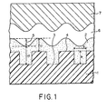
- FIG. 1 shows a schematical cross sectional view of an enbodiment of a part of the optical recording medium according to the present invention.
- a recording layer (2) is formed by coating a substrate (1) having groove portion (3) and land portion (4).
- a reflective layer (6) is formed on the recording layer and a protective layer (7) is formed on the reflective layer.
- the groove depth and width are indicated respectively by (8) and (9).
- the thickness of the recording layer at the groove portion and land portion are indicated by (10) and (11).
- the difference in height ( ⁇ T) between the surface of the recording layer on the land portion (4) and that on the groove portion (3) is indicated by (5).
- a transparent resin substrate used in the present invention such substrate capable of transmitting a light used for recording signals and readout of recorded information is preferable.
- Preferable transmittance of light is 85 % or higher. Further, it is preferable that optical anisotropy of the substrate is small.
- Examplary suitable substrates include thermoplastic resin substrates composed of acrylic resins, polycarbonate resins, polyamide resins, polyvinyl chloride, polyolefin resins or the like.
- acrylic resins, polycarbonate resins, or polyolefin resins are preferable, and polycarbonate resin is particularly preferable.
- These resins may be formed into the substrates by injection molding or cast molding.
- the shape of the substrate may be in the form of plate or film, or circle or card.
- the surface of the substrate is provided with grooves for controlling the recording position.
- the surface may have partly some prepits for the information.
- Such grooves and pits are preferably formed when the substrate is fabricated by injection molding or cast molding. Further they may be formed by applying an ultraviolet light curable resin to a substrate, superposing a stamper thereon and exposing to ultraviolet light.
- the optical recording medium comprises a transparent resin substrate, and a recording layer containing a dye, a reflective layer and a protective layer subsequently superposed on the substrate.
- the dyes used in the recording layer containing a dye may be dyes having absorption in the wavelength region of oscillation of semiconductor laser such as polymethine dye, phthalocyanine dye, naphthalocyanine dye, naphthoquinone dye, azulene dye, dithiol metal complex dye and the like.
- These dyes may have various substituents so as to control the solubility of the dye in a solvent to a desirable range or impart desirable recording characteristics.
- the dyes may be used alone or in combination.
- phthalocyanine dye and naphthalocyanine dye are preferable from the standpoints of light resistance and durability.
- the recording layer containing a dye can be usually formed by a coating method such as spin coating, spraying, dipping and the like.
- the dye When the above-mentioned dye is formed into a layer by a coating method, the dye may be dissolved in a solvent not adversely affecting the substrate.
- solvents are, for example, aliphatic or alicyclic hydrocarbons such as hexane, heptane, octane, decane, cyclohexane, methylcyclohexane, dimethylcyclohexane, cyclooctane and the like; ether type non-polar solvents such as diethyl ether, dibutyl ether, diisopropyl ether and the like; and alcoholic polar solvents such as methyl alcohol, ethyl alcohol, isopropyl alcohol, allyl alcohol, methyl cellosolve, and the like.
- the present invention it is important to control the shape (depth and width) of groove of the substrate, thickness of recording layer at the groove portion, that at the land portion and the surface shape ( ⁇ T) of the recording layer.
- the groove in the substrate is 90 - 180 nm (900 - 1800 ⁇ ) in depth and 0.3 - 0.6 ⁇ m in width and the thickness of recording layer at the groove portion is 80 - 125 nm (800 - 1250 ⁇ ) and that at the land is 50 - 110 nm (500 - 1100 ⁇ .) More preferably, the surface of recording layer at the land portion is higher than that at the groove portion by at least 50 nm (500 ⁇ .)
- the thickness of recording layer at the groove portion exceeding 125 nm (1250 ⁇ ) is not preferable since the error rate increases to a great extent when the medium is allowed to stand under high temperature and high humidity conditions for a long time.
- the thickness of recording layer at the land portion exceeding 110 nm (1100 ⁇ ) is not preferable since jitter value and error rate are deteriorated.
- the upper limit of the difference in height between the surface of recording layer at the land portion and that at the groove portion is preferably 120 nm (1200 ⁇ .)
- the difference exceeds 120 nm (1200 ⁇ the tracking error singnal becomes too large or assuring the reflectivity of groove of 60 % or more becomes difficult sometimes, and playability by commercially available CD player is not possible.
- the formation of the recording layer having a difference in height ( ⁇ T) between the surface of recording layer at the land portion and that at the groove portion of 50 nm (500 ⁇ ) or higher may be effected by controlling or selecting the depth of groove in the substrate, type of solvent (boiling point, vaporization speed, and surface tension) used for coating or coating conditions (rotating conditions in the case of spin coating).
- the difference in layer thickness between the recording layer at the groove portion and that at the land portion becomes larger.
- the shape (the depth and the width) of groove in the substrate and the shape ( ⁇ T) of the surface of recording layer at the land portion and groove portion can be measured by means of a scanning type tunnel microscope or by observing the cross section of the substrate and recording layer with a microscope.
- the thickness of the recording layer at the groove portion and land portion can be measured by observing the cross section of the recording layer with a microscope.
- the width of groove in the present invention is a half-value width, that is, the width at a position where the depth of groove is a half of the total depth.
- the Rc value is 0.05 or more at the unrecorded portion while it is 0.2 or more at the recorded portion.
- a recording layer containing a dye in addition to the dye used in the present invention, there may be used resins such as nitrocellulose, ethylcellulose, acrylic resins, polystyrene resins, urethane resins and the like, leveling agents, deforming agents and the like in an amount which does not adversely affect the effect of the present invention, for example, about 20 % or less, preferably about 10 % or less.
- resins such as nitrocellulose, ethylcellulose, acrylic resins, polystyrene resins, urethane resins and the like, leveling agents, deforming agents and the like in an amount which does not adversely affect the effect of the present invention, for example, about 20 % or less, preferably about 10 % or less.
- a metal thin film is preferably used as the reflective layer provided on the recording layer.
- the reflectivity of the medium is preferably 60 % or more.
- metals there may be mentioned aluminum, gold, silver, copper, platinum, nickel and the like and alloys containing the metals as mentioned above as a component or components.
- the reflective layer made of the metal may be formed by vapor deposition, sputtering and the like. In usual, the thickness of reflective layer is preferably 50 - 200 nm (500 - 2000 ⁇ .)
- a protective layer is formed on the reflective layer.
- resins are usually used. In particular, from the standpoint of productivity, ultroviolet light curable resins are preferable.
- the thickness of the protective layer is preferably about 1 - 15 ⁇ m.
- the optical recording medium of the present invention is irradiated with a laser beam through the substrate to record information signals or read out the information.
- Wavelength of the laser beam is preferably 640 - 850 nm.
- Semiconductor laser having an oscillatory wavelength of such range as above is preferably used.
- the laser output is made about 5 - 12 mW on the recording film while rotating the medium, and for readout, the laser output is made about 1/10 times that for recording.
- Printing may be made on the protective layer of the optical recording medium of the present invention.
- Pd-tetra-(t-butylcyclohexyloxy) phthalocyanine was prepared by using 3-(t-butylcyclohexyloxy)-1,2-dicyanobenzene and PdCl 2 according to a conventional method, for example, EP 232,427.
- Example 2 et seq. the dyes were prepared in a manner similar to the above-mentioned procedure.
- a 3.1 wt. % solution of a brominated (average 3.0 atoms/molecule) Pd-tetra-(t-butylcyclohexyloxy) phthalocyanine in methylcyclohexane was dropped on the center portion of the surface having a groove 140 nm (1400 ⁇ in depth, 0.5 ⁇ m in width, 1.6 ⁇ m in pitch) of an injection molded polycarbonate resin substrate of 1.2 mm thick and 120 mm in diameter. Then the resin substrate was rotated at a speed of 1000 rpm for 10 sec. The resin substrate was dried at 40°C for 10 min. and a recording layer substantially composed of a phthalocyanine dye was formed on a resin substrate.
- the thickness and surface shape of the recording layer was measured by obserbing the cross section by means of an electron microscope.
- a gold thin film of 80 nm thick as a reflective layer by means of sputtering, and further an ultraviolet ray-cured resin layer of 5 ⁇ m thick was formed on a reflective layer to produce an optical recording medium.
- Example 1 The procedure of Example 1 was repeated using the same dye as in Example 1 except that there were used a substrate having a groove of a shape, a solvent, a concentration of the solution and a rotating speed as shown below, and a medium was produced and evaluated.
- Example Shape of groove Solvent Concentration (% by weight) Rotating speed (rpm) Depth ( ⁇ ) (nm) Width ( ⁇ m) 2 (950) 95 0.35 Methylcyclohexane 2.8 1000 3 (1400) 140 0.50 Dibutyl ether 3.1 700 4 (950) 95 0.35 Octane 3.1 700 Comparative Example 1 (950) 95 0.35 Octane 3.5 700 2 (950) 95 0.35 Methylcyclohexane 3.0 1100 3 (800) 80 0.35 Methylcyclohexane 3.1 1100 4 (1900) 190 0.58 Ethylcyclohexane 2.1 1000 5 (950) 95 0.70 Methylcyclohexane 3.1 1000
- Example 2 The procedure of Example 1 was repeated except that there were used a substrate having a groove of a shape, a solution having a concentration of a brominated (average 3.5 atoms/molecule) Pd-tetra-(t-butylcyclohexyloxy)phthalocyanine dye in a solvent and a rotating speed as shown below, and a medium was produced and evaluated.
- Example Shape of groove Solvent Concentration (% by weight) Rotating speed (rpm) Depth ( ⁇ ) (nm) Width ( ⁇ m) 5 (1600) 160 0.5 Dibutyl ether 4.0 700 6 (1600) 160 0.5 Ethylcyclohexane 4.0 700
- Example 2 The procedure of Example 1 was repeated except that there were used a substrate having a groove of a shape, a solution having a concentration of a brominated (average 3.5 atoms/molecule) Pd-tetra-(2,4-dimethyl-pentan-3-oxy) phthalocyanine in a solvent and a rotating speed as shown below, and a medium was produced and evaluated.
- the examples of the present invention all exhibit high reflectivity and sufficiently low jitter values and error rates.
- the radial contrast is large both at unrecorded portion and recorded portion.
- the mediums have a good playability by commercially available CD players. Even when the mediums are allowed to stand under high temperature and high humid conditions, they exhibit excellent characteristics such that the jitter values and error rates are hardly changed.
- the layer thickness of the recording layer at the groove portion is thick so that after the durability test, error rates increased to a great extent.
- the mediums subjected to such durability test were observed with an electron microscope, it was found that a defect of about 2 ⁇ m was formed at the center of pit.
Claims (4)
- Ein optisches Aufzeichnungsmaterial vom Einplattentyp mit der Fähigkeit aufzuzeichnen, das einen durchsichtigen Kunststoffträger (1) mit einer Rille (3) und einer hervorstehenden Fläche (4), eine Aufzeichnungsschicht (2), die einen Farbstoff enthält und über dem Träger liegt, eine reflektierende Schicht (6), die über der Aufzeichnungsschicht liegt, und eine Schutzschicht (7), die über der reflektierenden Schicht liegt, umfaßt, und bei dem die Dicke der Aufzeichnungsschicht 80 - 125 nm an dem Rillenabschnitt (10) und 50 - 110 nm an dem hervorstehenden Flächenabschnitt (11) ist, dadurch gekennzeichnet, daß die Rillentiefe (8) 90 - 180 nm beträgt und die Rillenbreite (9) 0,3 - 0,6 µm ist und die Differenz der Höhe (5) zwischen der Oberfläche der Aufzeichnungsschicht auf dem hervorstehenden Flächenabschnitt und derjenigen auf dem Rillenabschnitt 50 - 120 nm beträgt.
- Das optische Aufzeichnungsmaterial nach Anspruch 1, bei dem das Reflektionsvermögen an einem nicht für die Aufzeichnung verwendeten Abschnitt an dem Rillenabschnitt durch den Träger 60 % oder höher ist.
- Das optische Aufzeichnungsmaterial nach Anspruch 2, bei dem die Aufzeichnungsschicht einen Phthalocyaninfarbstoff enthält.
- Das optische Aufzeichnungsmaterial nach einem der Ansprüche 1 - 3, bei dem Signale in der Rille durch Lochpunkt-Längsaufzeichnung aufgezeichnet werden.
Applications Claiming Priority (2)
| Application Number | Priority Date | Filing Date | Title |
|---|---|---|---|
| JP8378491 | 1991-04-16 | ||
| JP83784/91 | 1991-04-16 |
Publications (2)
| Publication Number | Publication Date |
|---|---|
| EP0509423A1 EP0509423A1 (de) | 1992-10-21 |
| EP0509423B1 true EP0509423B1 (de) | 1997-07-02 |
Family
ID=13812263
Family Applications (1)
| Application Number | Title | Priority Date | Filing Date |
|---|---|---|---|
| EP92106324A Expired - Lifetime EP0509423B1 (de) | 1991-04-16 | 1992-04-12 | Optischer Aufzeichnungsträger |
Country Status (7)
| Country | Link |
|---|---|
| US (1) | US5369321A (de) |
| EP (1) | EP0509423B1 (de) |
| KR (1) | KR950001877B1 (de) |
| CA (1) | CA2065653A1 (de) |
| DE (1) | DE69220609T2 (de) |
| SG (1) | SG52484A1 (de) |
| TW (1) | TW245798B (de) |
Families Citing this family (10)
| Publication number | Priority date | Publication date | Assignee | Title |
|---|---|---|---|---|
| JPH08306069A (ja) * | 1995-05-11 | 1996-11-22 | Seiko Epson Corp | 光ディスクおよび光ディスクの製造方法 |
| US5959960A (en) * | 1996-09-27 | 1999-09-28 | Eastman Kodak Company | Method of providing a range of conformalities for optical recording layers |
| GB9903550D0 (en) * | 1999-02-16 | 1999-04-07 | Plasmon Ltd | Forming optical recording layers |
| JP2001344812A (ja) * | 2000-06-02 | 2001-12-14 | Fuji Photo Film Co Ltd | 光情報記録媒体 |
| JP2005515581A (ja) * | 2002-01-18 | 2005-05-26 | コーニンクレッカ フィリップス エレクトロニクス エヌ ヴィ | 光学式データ記憶媒体とその媒体の利用 |
| JP2005190616A (ja) * | 2003-12-26 | 2005-07-14 | Taiyo Yuden Co Ltd | 光情報記録媒体 |
| ATE352587T1 (de) | 2004-07-29 | 2007-02-15 | Clariant Finance Bvi Ltd | Azoliganden auf der basis von aminoantipyrine und ihre metallkomplexe zur verwendung als optische aufzeichnungsmedien |
| JP2008010107A (ja) * | 2006-06-30 | 2008-01-17 | Toshiba Corp | 情報記録媒体、及びディスク装置 |
| JP2008010129A (ja) * | 2006-06-30 | 2008-01-17 | Toshiba Corp | 情報記録媒体、及びディスク装置 |
| JP5408851B2 (ja) * | 2007-07-31 | 2014-02-05 | 太陽誘電株式会社 | 光情報記録媒体 |
Family Cites Families (6)
| Publication number | Priority date | Publication date | Assignee | Title |
|---|---|---|---|---|
| US4359750A (en) * | 1981-04-30 | 1982-11-16 | Eastman Kodak Company | Optical disc structure |
| JPH0823941B2 (ja) * | 1988-11-08 | 1996-03-06 | パイオニア株式会社 | 光学式情報記録担体及びその製造方法 |
| EP0385341B1 (de) * | 1989-03-03 | 2000-05-24 | TDK Corporation | Medium für optische Datenspeicherung |
| MY105953A (en) * | 1989-07-24 | 1995-02-28 | Taiyo Yuden Kk | Optical information recording medium and recording method. |
| US5274623A (en) * | 1990-07-19 | 1993-12-28 | Fuji Photo Film Co., Ltd. | Information recording medium having high modulation degree |
| US5213859A (en) * | 1990-12-21 | 1993-05-25 | Tdk Corporation | Optical recording disk |
-
1992
- 1992-04-09 CA CA002065653A patent/CA2065653A1/en not_active Abandoned
- 1992-04-12 SG SG1996005127A patent/SG52484A1/en unknown
- 1992-04-12 EP EP92106324A patent/EP0509423B1/de not_active Expired - Lifetime
- 1992-04-12 DE DE69220609T patent/DE69220609T2/de not_active Expired - Fee Related
- 1992-04-13 TW TW081102866A patent/TW245798B/zh active
- 1992-04-15 KR KR1019920006279A patent/KR950001877B1/ko not_active IP Right Cessation
-
1994
- 1994-04-18 US US08/229,063 patent/US5369321A/en not_active Expired - Lifetime
Also Published As
| Publication number | Publication date |
|---|---|
| KR920020429A (ko) | 1992-11-21 |
| SG52484A1 (en) | 1998-09-28 |
| KR950001877B1 (ko) | 1995-03-04 |
| TW245798B (de) | 1995-04-21 |
| DE69220609D1 (de) | 1997-08-07 |
| DE69220609T2 (de) | 1998-01-08 |
| CA2065653A1 (en) | 1992-10-17 |
| US5369321A (en) | 1994-11-29 |
| EP0509423A1 (de) | 1992-10-21 |
Similar Documents
| Publication | Publication Date | Title |
|---|---|---|
| US5075147A (en) | Method for optically recording information and information recorded medium | |
| US6287660B1 (en) | Optical recording medium and its substrate | |
| US5391461A (en) | Optical recording medium and recording method | |
| EP0509423B1 (de) | Optischer Aufzeichnungsträger | |
| KR960016142B1 (ko) | 광기록매체 | |
| US5441848A (en) | Optical recording/reproducing method | |
| US5270150A (en) | Optical recording medium and process for producing it | |
| EP0455124B1 (de) | Optisches Aufzeichnungsmedium und Verfahren zu dessen Herstellung | |
| JPH04358331A (ja) | 光情報記録媒体 | |
| JP3649062B2 (ja) | 光記録媒体及び光記録方法 | |
| JP3177291B2 (ja) | 光記録媒体 | |
| JP2512044B2 (ja) | 光記録媒体及び光記録方法 | |
| KR20010040914A (ko) | 얇은 기록층을 갖는 광기록매체 | |
| JP2512043B2 (ja) | 光記録媒体及び光記録方法 | |
| JP3073266B2 (ja) | 光記録媒体の製造方法 | |
| JPS63298836A (ja) | 光記録媒体およびその製造方法 | |
| JPH04286684A (ja) | 光記録媒体 | |
| JPH02187937A (ja) | 光記録媒体および光記録再生方法 | |
| JPH02201748A (ja) | 光記録媒体 | |
| JP3693478B2 (ja) | 光記録媒体の製造方法 | |
| US20030161987A1 (en) | Optical recording medium | |
| JPH02187939A (ja) | 光記録媒体および光記録再生方法 | |
| JPH05198012A (ja) | 光記録媒体、光記録媒体用基板及びスタンパー | |
| JPH04315834A (ja) | 光記録媒体 | |
| JPH04344345A (ja) | 光記録媒体 |
Legal Events
| Date | Code | Title | Description |
|---|---|---|---|
| PUAI | Public reference made under article 153(3) epc to a published international application that has entered the european phase |
Free format text: ORIGINAL CODE: 0009012 |
|
| 17P | Request for examination filed |
Effective date: 19920820 |
|
| AK | Designated contracting states |
Kind code of ref document: A1 Designated state(s): CH DE FR GB IT LI NL |
|
| 17Q | First examination report despatched |
Effective date: 19950706 |
|
| GRAG | Despatch of communication of intention to grant |
Free format text: ORIGINAL CODE: EPIDOS AGRA |
|
| GRAH | Despatch of communication of intention to grant a patent |
Free format text: ORIGINAL CODE: EPIDOS IGRA |
|
| GRAH | Despatch of communication of intention to grant a patent |
Free format text: ORIGINAL CODE: EPIDOS IGRA |
|
| GRAA | (expected) grant |
Free format text: ORIGINAL CODE: 0009210 |
|
| AK | Designated contracting states |
Kind code of ref document: B1 Designated state(s): CH DE FR GB IT LI NL |
|
| PG25 | Lapsed in a contracting state [announced via postgrant information from national office to epo] |
Ref country code: CH Free format text: LAPSE BECAUSE OF FAILURE TO SUBMIT A TRANSLATION OF THE DESCRIPTION OR TO PAY THE FEE WITHIN THE PRESCRIBED TIME-LIMIT Effective date: 19970702 Ref country code: LI Free format text: LAPSE BECAUSE OF FAILURE TO SUBMIT A TRANSLATION OF THE DESCRIPTION OR TO PAY THE FEE WITHIN THE PRESCRIBED TIME-LIMIT Effective date: 19970702 |
|
| REG | Reference to a national code |
Ref country code: CH Ref legal event code: EP |
|
| REF | Corresponds to: |
Ref document number: 69220609 Country of ref document: DE Date of ref document: 19970807 |
|
| ITF | It: translation for a ep patent filed |
Owner name: STUDIO TORTA S.R.L. |
|
| ET | Fr: translation filed | ||
| REG | Reference to a national code |
Ref country code: CH Ref legal event code: PL |
|
| PGFP | Annual fee paid to national office [announced via postgrant information from national office to epo] |
Ref country code: NL Payment date: 19980428 Year of fee payment: 7 |
|
| PLBE | No opposition filed within time limit |
Free format text: ORIGINAL CODE: 0009261 |
|
| STAA | Information on the status of an ep patent application or granted ep patent |
Free format text: STATUS: NO OPPOSITION FILED WITHIN TIME LIMIT |
|
| 26N | No opposition filed | ||
| REG | Reference to a national code |
Ref country code: GB Ref legal event code: 732E |
|
| REG | Reference to a national code |
Ref country code: FR Ref legal event code: TP |
|
| NLS | Nl: assignments of ep-patents |
Owner name: MITSUI CHEMICALS, INC. |
|
| PG25 | Lapsed in a contracting state [announced via postgrant information from national office to epo] |
Ref country code: NL Free format text: LAPSE BECAUSE OF NON-PAYMENT OF DUE FEES Effective date: 19991101 |
|
| NLV4 | Nl: lapsed or anulled due to non-payment of the annual fee |
Effective date: 19991101 |
|
| REG | Reference to a national code |
Ref country code: GB Ref legal event code: IF02 |
|
| PG25 | Lapsed in a contracting state [announced via postgrant information from national office to epo] |
Ref country code: IT Free format text: LAPSE BECAUSE OF NON-PAYMENT OF DUE FEES;WARNING: LAPSES OF ITALIAN PATENTS WITH EFFECTIVE DATE BEFORE 2007 MAY HAVE OCCURRED AT ANY TIME BEFORE 2007. THE CORRECT EFFECTIVE DATE MAY BE DIFFERENT FROM THE ONE RECORDED. Effective date: 20050412 |
|
| PGFP | Annual fee paid to national office [announced via postgrant information from national office to epo] |
Ref country code: FR Payment date: 20090417 Year of fee payment: 18 Ref country code: DE Payment date: 20090409 Year of fee payment: 18 |
|
| PGFP | Annual fee paid to national office [announced via postgrant information from national office to epo] |
Ref country code: GB Payment date: 20090408 Year of fee payment: 18 |
|
| GBPC | Gb: european patent ceased through non-payment of renewal fee |
Effective date: 20100412 |
|
| REG | Reference to a national code |
Ref country code: FR Ref legal event code: ST Effective date: 20101230 |
|
| PG25 | Lapsed in a contracting state [announced via postgrant information from national office to epo] |
Ref country code: DE Free format text: LAPSE BECAUSE OF NON-PAYMENT OF DUE FEES Effective date: 20101103 |
|
| PG25 | Lapsed in a contracting state [announced via postgrant information from national office to epo] |
Ref country code: GB Free format text: LAPSE BECAUSE OF NON-PAYMENT OF DUE FEES Effective date: 20100412 |
|
| PG25 | Lapsed in a contracting state [announced via postgrant information from national office to epo] |
Ref country code: FR Free format text: LAPSE BECAUSE OF NON-PAYMENT OF DUE FEES Effective date: 20100430 |