EP0509115B1 - Système de commande de dépression pour moyens de levage - Google Patents
Système de commande de dépression pour moyens de levage Download PDFInfo
- Publication number
- EP0509115B1 EP0509115B1 EP91106132A EP91106132A EP0509115B1 EP 0509115 B1 EP0509115 B1 EP 0509115B1 EP 91106132 A EP91106132 A EP 91106132A EP 91106132 A EP91106132 A EP 91106132A EP 0509115 B1 EP0509115 B1 EP 0509115B1
- Authority
- EP
- European Patent Office
- Prior art keywords
- housing
- control
- air
- length
- load
- Prior art date
- Legal status (The legal status is an assumption and is not a legal conclusion. Google has not performed a legal analysis and makes no representation as to the accuracy of the status listed.)
- Expired - Lifetime
Links
- 230000007246 mechanism Effects 0.000 claims description 42
- 230000008878 coupling Effects 0.000 claims 1
- 238000010168 coupling process Methods 0.000 claims 1
- 238000005859 coupling reaction Methods 0.000 claims 1
- 230000007812 deficiency Effects 0.000 description 3
- 238000013022 venting Methods 0.000 description 3
- 238000010276 construction Methods 0.000 description 2
- 230000003247 decreasing effect Effects 0.000 description 2
- 230000000694 effects Effects 0.000 description 2
- 238000002789 length control Methods 0.000 description 2
- 230000007257 malfunction Effects 0.000 description 2
- 230000000750 progressive effect Effects 0.000 description 2
- 230000003111 delayed effect Effects 0.000 description 1
- 230000001419 dependent effect Effects 0.000 description 1
- 238000010586 diagram Methods 0.000 description 1
- 230000003993 interaction Effects 0.000 description 1
- 238000000034 method Methods 0.000 description 1
- 230000002028 premature Effects 0.000 description 1
- 238000005086 pumping Methods 0.000 description 1
- 230000004044 response Effects 0.000 description 1
- 238000007789 sealing Methods 0.000 description 1
- 230000007704 transition Effects 0.000 description 1
- 238000005303 weighing Methods 0.000 description 1
Images
Classifications
-
- B—PERFORMING OPERATIONS; TRANSPORTING
- B66—HOISTING; LIFTING; HAULING
- B66F—HOISTING, LIFTING, HAULING OR PUSHING, NOT OTHERWISE PROVIDED FOR, e.g. DEVICES WHICH APPLY A LIFTING OR PUSHING FORCE DIRECTLY TO THE SURFACE OF A LOAD
- B66F3/00—Devices, e.g. jacks, adapted for uninterrupted lifting of loads
- B66F3/24—Devices, e.g. jacks, adapted for uninterrupted lifting of loads fluid-pressure operated
- B66F3/25—Constructional features
- B66F3/35—Inflatable flexible elements, e.g. bellows
Definitions
- This invention relates to vacuum powered lifting and transport systems and more particularly it relates to pressure control within a vacuum powered lifting mechanism that changes in length with differences in air pressure.
- Vacuum powered lifting and transport systems are known in the prior art.
- One example is shown in U. S. Patent 4,413,853, S. Andersson, Nov. 8, 1983, wherein a tubing that changes length with internal air pressure is shortened by means of a vacuum source to lift a work object by vacuum suction and transport it to another location.
- air pressure control systems employed in vacuum powered lifts to engage, lift, transport and release heavy work load objects have critical ranges of load positioning and work object grasping and releasing procedures requiring significant concentration and skill by an operator.
- operators must become very skilled in controlling air pressure changes particularly when lowering heavy work load objects to a terminal location under transition conditions from near atmospheric pressure to minimum pressures supplied by a vacuum source, to prevent premature release or mispositioning of the work object, which can impact with accompanying danger of damage to equipment or operator.
- a power lifting system according to the introductory part of claim 1 is disclosed in GB-A-2,200,615.
- This power system comprises a differential pressure control means for introducing atmospheric air into the housing for controlling the length thereof.
- This pressure control means comprises a plug which is tapered at its forward end and enters a cylindrical sleeve to control the flow of atmospheric air. Very small manual movements during the movement of the plug taper into the sleeve result in very large differences in the height of the load causing great difficulty in manual control of the load height.
- a safer vacuum powered lift and transport system that extends the functional performance and eliminates tedious and critical operator dependent controls is provided in accordance with this invention by means of a combination of novel control features interacting with the vacuum system.
- height adjustment means establishing a predetermined operator-independent variable maximum height of the lifting mechanism for both unloaded and loaded conditions, and providing uncritical manually operable pressure control mechanisms for proportionately changing the vertical position of a work load object over a smooth uncritical progressive and substantially linear movement range of a control member.
- a manually operable length control mechanism provides internal pressure control within a lifting mechanism that vertically retracts and thus lifts by means of a vacuum source. This provides a control member movable over a substantially linear range of manual movement producing proportional changes in length of the lifting mechanism.
- valve mechanism for injecting a flow of air into the mechanism body to increase pressure and thus extend the body length proportionately with movement of a manually controlled member that opens up a corresponding portion of the length of an injecting slot outlet port through which the air flow path is directed.
- the nominal closed position of this proportionate control valve mechanism is variably adjustable to feed a predetermined flow of air that establishes a predetermined safe upper limit of vertical lift movement in response to a vacuum pumping source.
- the internal air pressure of the lifting mechanism is further controlled adjustably to a predetermined pressure in the absence of a work load object in the grasp to establish an optimal no-load height.
- Critical control of the elongated condition near maximum air flow into the lifter body during lowering and release or in readiness for grasping a new work load object is eliminated by linearizing air flow control means so that the operator need not be well trained and need not encounter critical conditions.
- An air vented lifting body grasping surface eliminates the possibilities of failing to grasp a work object in position for lifting and transport.
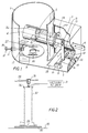
- the primary control mechanism 1 for the system may be located in the lower lifting mechanism body portion generally comprising the lowermost cylindrical cap to the expandable and retractable body portion 30. Its collapsed length is controlled by restricting the air flow into the vacuum source 31 and internal air pressure modifying means for lengthening the body 30.
- the specific control mechanisms of Figure 1 thus control grasping, balancing, lifting, transporting, lowering and releasing the work load object 32 from or onto a work surface 33, which might be a movable conveyor or a factory floor.
- the transport line 34 typically provides for transport of the lifted work object 32 to another location by means of riding carriage 35, coupled to an uppermost cap 36 on the lifting mechanism body 30.
- the differential in pressure inside the lifting mechanism body 30 and the atmosphere as provided by the balancing of the vacuum source 31 with injected atmospheric air will proportion the retraction or foreshortening of the vertically disposed longitudinal lift mechanism body 30 to lift the work body objects 32 upwardly off the surface 33 for transport.
- the longitudinally positioned valve slot 26 is cut into the side wall of the valve body 4.
- a longitudinally movable diaphragm or control valve member 5 opens more or less of the length of slotted exit port 26 to release air by the axial positioning of the member 5 by way of control rod member 6 to move within the valve body 4 cylinder, or equivalent valve housing.
- Control rod 6 is thus reciprocated as represented by the two headed arrow, typically by a human operator supplied with a suitable control handle (not shown). This is a critical operation for controlling the length of the lift mechanism and the grasping, movement and releasing of the work object. In particular control is most critical in the lengthening of the tube to lower and release a work product or to grasp it by increasing the flow of air into the lift body.
- Balancing of the vacuum source contribution and increased pressure due to input atmospheric air is necessary to lower the lifting mechanism for grasping the work body object when unloaded. Also critical is the lowering of a work load object, which must be precisely controlled by increased input air flow to balance the vacuum source contribution for lowering the work load object to deposit it on the work surface. Disproportionate and critical operator control means for this in prior art systems introduced operator concern and tediousness, required critically trained and experienced operators and produced risks of dropping a work load object with potential danger to personnel or equipment or in an improper location.
- This invention provide the precision proportional control by the operating lever of the length of the lifting mechanism over a substantially linear direction, which is afforded by the shape of the slot 26 serving as air exit port 24 in the preferred embodiment.
- exit port shape is controlled for the dimensions of the lift body and the vacuum source characteristics in a manner easily determined by those skilled in the art to achieve a substantially linear and proportional control with movement of the control lever 6 in a manner that is uncritical to require little skill and experience from an operator.
- Other shapes and configurations of this valve structure will become evident from the teachings of this invention.
- this invention provides the operator with means for smooth, progressive and substantially linear control of the length of the lifting mechanism and therefore enables precision placement, grasping, lifting, transport and release of work products in a manner not heretofore feasible with prior art system controls.
- variableably adjustable height control means for producing an operator-independent uppermost lifting limit under both the conditions of no-load and full load.
- control means operate to vent variably adjustable minimal magnitudes of flow of air into the lift mechanism body by means of two adjustable venting valves.
- the sliding valve plate 8 is provided to effect a first control function of establishing the predetermined height which the control unit of Fig. 2 will take in the absence of a load.
- the load supplied by a work load object to be lifted is disposed below the bottom plate 2 and serves to seal the vent 25 when the lift control valve member 4 establishes a reduced pressure by occluding the air vent slot 26.
- the decreased pressure within the lift mechanism body in essence sucks the surface of the work load object into surface contact.
- the vent valve opening 25 is adjusted to vent in the absence of a work load a predetermined amount of air that will cause the lift mechanism to shorten and raise the control unit 1 to a predetermined height in a normally inactive condition with the vacuum source attached.
- the knob 12 of adjustment screw 19 moves adjustment valve plate 8 over a part of the vent opening 25 as permitted by the bolt-slot assembly 20, with the adjustment screw threaded through the housing at 11 to move the valve flange member 17 reciprocally.
- the size of the venting aperture 25 is thus controlled so that the unloaded control unit 1 will lift to an established pre-set position and hang there when the lifting valve 5 is in its normally closed inactive position and a work load object is not grasped to seal the vent valve opening 25.
- this structure provides a continuous flow of air in the absence of the work load so that the vent is not sealed. This provides assurance of an immediate grasp of the work load without complicated manipulation of pressure controls or repositioning of the bottom plate 2 as the pressure within the lifting housing is decreased from its highest pressure limit at which the housing is extended at its longest length.
- the opening size control means also serves through the access port to assure a maximum vacuum sealing grasp for a work object located below the bottom plate 2.
- the screw assembly 22 is provided for adjusting a stop position for the control valve operating rod 6 in the normally inactive position attained by means of the bias spring 14 in the absence of active manual or equivalent control movement of the control rod 6.
- the screw is threaded through the enclosure body 3 to move the pivot arm 7 about the axis of pivot rod 16 mounted in bearing blocks 9 by means of bolts 21.
- Pivot arm 7 is slotted at 15 for movement of the pivot pin in control rod 6 over the arc of movement of the pivot arm 7 and accompanying linear axial movement of control rod 6.
- the screw assembly 22 thus establishes a minimal opening size of the slotted vent port 26 in control valve 5 for feeding atmospheric air into the lift mechanism body to prevent a low enough pressure established by the vacuum source to retract the length of the lift mechanism beyond a point establishing a maximum height of the work piece object under load when port 25 is closed.
- the return spring 13 is slightly weaker than the bias spring 14 interposed in the adjustment link. Thus, the return spring 13 does not cause the slot 26 to be fully opened when the operator releases control rod 6 to let it return to its normal position, with the vacuum source connected.
- the length of the lift mechanism is adjusted in that condition by the screw assembly 22 to determine the maximum height and to assure a minimum pressure limit inside the lift mechanism body from the vacuum source. It is assured then that a loaded lift will attain a predetermined operator-independent height, as well as an unloaded lift, respectively by means of adjustment screws 22 and 19.
- control mechanism of this invention operates the vacuum powered lifting system in different modes of operation than prior art systems to overcome the deficiencies in the prior art heretofore set forth.
- the proportional movement of the lift mechanism with the position of the control rod 6 thus gives noncritical control of a load, particularly in the lowering release operation, which has been critical and hard to adjust in prior art vacuum lift systems.
- the control valve slot 26 at a critical position along the vertical axis of the lifting mechanism the lift body lengthens to lower a work load object over a distance proportional to the movement of the control rod 6.
- the operator thus has to have no particular expertise and need not be concerned with critical concentration to operate a valve through a critical and sensitive non-linear region where very small movements of a control lever cause very large changes in interior lift housing pressure as provided in prior art systems.
Landscapes
- Life Sciences & Earth Sciences (AREA)
- Engineering & Computer Science (AREA)
- Geology (AREA)
- Mechanical Engineering (AREA)
- Structural Engineering (AREA)
- Sheets, Magazines, And Separation Thereof (AREA)
- Load-Engaging Elements For Cranes (AREA)
- Prostheses (AREA)
- Acyclic And Carbocyclic Compounds In Medicinal Compositions (AREA)
Claims (5)
- Système de levage mû par dépression comprenant une source de dépression (31), une enceinte de mécanisme de levage (30) de longueur variable couplée à la source de dépression de sorte que sa longueur varie en fonction de la pression différentielle dans l'enceinte (30) par rapport à la pression atmosphérique, des moyens de couplage de charge (2, 25) pour coupler le mécanisme de levage à une charge de travail à lever et à transporter par une pression réduite en provenance de la source de dépression, un moyen de commande de pression différentielle (1) pour introduire de l'air atmosphérique dans l'enceinte (30) pour commander la longueur de l'enceinte (30), et un élément de commande mobile manuellement (6) actionnable pour commander le débit d'air atmosphérique dans l'enceinte, une vanne de fourniture d'air (4, 5) commandée par l'élément de commande (6) pour modifier, par la longueur du déplacement manuel de l'élément de commande (6) sur une plage de commande spécifiée de longueur de travail de l'enceinte (30), le débit d'air atmosphérique dans l'enceinte (30), pour modifier ainsi la longueur correspondante de l'enceinte, de façon sensiblement proportionnelle à la longueur du déplacement manuel de l'élément de commande (6),
caractérisé par une fente (26) formant évent et un élément de vanne de commande variable (5) pour faire occlusion à l'air à travers la fente d'évent (26) mobile le long de la fente d'évent (26) sous l'effet de l'élément de commande (6) disposé dans la vanne de fourniture d'air (4, 5) pour contrôler le débit d'air atmosphérique entrant dans l'enceinte (30) et modifier ainsi la longueur de l'enceinte (30) proportionnellement à l'amplitude du déplacement de l'élément de commande (6). - Système de levage selon la revendication 1, caractérisé en outre par des moyens de commande de hauteur (22, 7, 13, 15) pour établir une position normale de l'élément de commande quand il n'est pas commandé manuellement de façon variable par un opérateur pour établir une pression suffisamment faible dans le boîtier (30) à partir de la source de dépression (31) pour établir une hauteur maximum de la charge de travail (32) quand la fente d'évent (26) est bouchée par les éléments de commande (5, 6) dans une position de levage maximum dans la plage de commande.
- Système de levage selon l'une des revendications précédentes, caractérisé en outre par des moyens de vanne de réglage de hauteur (8, 11, 12, 19, 20) pour fixer la longueur de l'enceinte (30) dans des conditions de non-charge.
- Système de levage selon l'une des revendications précédentes, caractérisé en outre par une surface de prise d'objet (2) pour établir une communication de circulation d'air entre la pression différentielle dans l'enceinte (30) et une surface de l'objet formant charge (32) quand l'élément de commande (6) est positionné pour lever une charge, fournissant ainsi un accès d'entrée de débit d'air normalement ouvert (25) sur la surface de prise (2) pour introduire en continu un débit d'air dans le corps quand une charge de travail (32) n'est pas saisie.
- Système de levage selon la revendication 4, caractérisé en outre par des moyens de commande réglables (8, 11, 12, 19, 20) actionnables par l'accès d'entrée de débit d'air (25) pour établir une hauteur prédéterminée que prend l'enceinte en l'absence de charge (32).
Priority Applications (2)
| Application Number | Priority Date | Filing Date | Title |
|---|---|---|---|
| AT91106132T ATE127766T1 (de) | 1991-04-17 | 1991-04-17 | Unterdruck-steuersystem für hebevorrichtungen. |
| DE1991613021 DE69113021T2 (de) | 1991-04-17 | 1991-04-17 | Unterdruck-Steuersystem für Hebevorrichtungen. |
Applications Claiming Priority (1)
| Application Number | Priority Date | Filing Date | Title |
|---|---|---|---|
| US07/500,969 US5035456A (en) | 1990-03-29 | 1990-03-29 | Vacuum control system for lifting systems |
Publications (2)
| Publication Number | Publication Date |
|---|---|
| EP0509115A1 EP0509115A1 (fr) | 1992-10-21 |
| EP0509115B1 true EP0509115B1 (fr) | 1995-09-13 |
Family
ID=23991622
Family Applications (1)
| Application Number | Title | Priority Date | Filing Date |
|---|---|---|---|
| EP91106132A Expired - Lifetime EP0509115B1 (fr) | 1990-03-29 | 1991-04-17 | Système de commande de dépression pour moyens de levage |
Country Status (3)
| Country | Link |
|---|---|
| US (1) | US5035456A (fr) |
| EP (1) | EP0509115B1 (fr) |
| CA (1) | CA2038775A1 (fr) |
Cited By (1)
| Publication number | Priority date | Publication date | Assignee | Title |
|---|---|---|---|---|
| DE102020128380A1 (de) | 2020-10-28 | 2022-04-28 | AERO-LIFT Vakuumtechnik Gesellschaft mit beschränkter Haftung | Schlauchheber |
Families Citing this family (11)
| Publication number | Priority date | Publication date | Assignee | Title |
|---|---|---|---|---|
| US5035456A (en) * | 1990-03-29 | 1991-07-30 | Robert Messinger | Vacuum control system for lifting systems |
| GB9100056D0 (en) * | 1991-01-03 | 1991-02-20 | Palamatic Handling Syst | Valve arrangement |
| US5221117A (en) * | 1992-04-30 | 1993-06-22 | Messinger Robert A | Fully rotatable vacuum lift with self contained utility lines |
| JP2826045B2 (ja) * | 1992-10-02 | 1998-11-18 | 株式会社キトー | 真空リフト装置 |
| US5816635A (en) * | 1994-07-26 | 1998-10-06 | Ljungblad-Petre Maskin Ab | Chock valve for a vacuum lifting device |
| DE19614479C1 (de) * | 1996-04-12 | 1997-07-24 | Schmalz J Gmbh | Unterdruck Handhabungsgerät |
| DE10038013B4 (de) * | 2000-08-04 | 2005-11-03 | Albert Fezer Maschinenfabrik Gmbh | Steuergerät für eine Vakuum-Hebevorrichtung |
| CN108349093B (zh) * | 2015-09-08 | 2022-01-14 | 伯克希尔格雷股份有限公司 | 用于在活节臂末端执行器中提供动态真空压力的系统和方法 |
| US10814498B2 (en) | 2017-11-07 | 2020-10-27 | Berkshire Grey, Inc. | Systems and methods for providing dynamic vacuum pressure at an end effector using a single vacuum source |
| EP4247599B1 (fr) | 2020-11-19 | 2025-08-20 | Berkshire Grey Operating Company, Inc. | Systèmes et procédés de traitement d'objets faisant appel à des dispositifs de préhension pour des objets ayant une faible aptitude à conserver une pose |
| DE102022132993A1 (de) * | 2022-12-12 | 2024-06-13 | Timmer Gmbh | Vakuum-Hebevorrichtung |
Citations (1)
| Publication number | Priority date | Publication date | Assignee | Title |
|---|---|---|---|---|
| US5035456A (en) * | 1990-03-29 | 1991-07-30 | Robert Messinger | Vacuum control system for lifting systems |
Family Cites Families (14)
| Publication number | Priority date | Publication date | Assignee | Title |
|---|---|---|---|---|
| GB376110A (en) * | 1931-10-05 | 1932-07-07 | Fritz Neuenschwander | Lifting tackle, for cranes with crabs |
| FR87687E (fr) * | 1964-04-22 | 1966-09-23 | Staubli Freres & Cie | Perfectionnements aux vannes de réglage de débit à écoulement axial |
| DE1431936A1 (de) * | 1965-11-13 | 1969-04-24 | Hasenclever Ag Maschf | Vorrichtung zum Heben und Senken von Lasten |
| FR1474799A (fr) * | 1965-12-30 | 1967-03-31 | Bertin & Cie | Dispositif de ventouse porte-charge |
| US3558171A (en) * | 1967-11-15 | 1971-01-26 | Netzsch Maschinenfabrik | Pneumatic arrangement for transferring articles |
| DE1924293B2 (de) * | 1969-05-13 | 1972-01-27 | Demag Ag, 4100 Duisburg | Saugkopf fuer feste koerper |
| CH526461A (de) * | 1971-02-10 | 1972-08-15 | Gis Ag | Unterdruck-Hebevorrichtung |
| FR2370660A1 (fr) * | 1976-11-12 | 1978-06-09 | Thierion Michel | Ventouse a depression pour la prise d'objets a position mal determinee |
| US4397331A (en) * | 1978-09-29 | 1983-08-09 | Honeywell Inc. | Fluid flow control valve with maximized noise reduction |
| US4266905A (en) * | 1979-04-20 | 1981-05-12 | Board Of Regents For Education Of The State Of Rhode Island | Apparatus for acquiring workpieces from a storage bin or the like |
| SE446621B (sv) * | 1980-02-04 | 1986-09-29 | Sten Andersson | Vakuumlyftanordning for gods eller andra foremal |
| US4384592A (en) * | 1980-11-28 | 1983-05-24 | International Telephone And Telegraph Corporation | Low-noise valve trim |
| GB2200615A (en) * | 1987-01-22 | 1988-08-10 | Portec Inc | Suction actuated lifting apparatus |
| GB8828914D0 (en) * | 1988-12-10 | 1989-01-18 | Palamatic Handling Syst | Vacuum lifting apparatus |
-
1990
- 1990-03-29 US US07/500,969 patent/US5035456A/en not_active Expired - Lifetime
-
1991
- 1991-03-27 CA CA002038775A patent/CA2038775A1/fr not_active Abandoned
- 1991-04-17 EP EP91106132A patent/EP0509115B1/fr not_active Expired - Lifetime
Patent Citations (1)
| Publication number | Priority date | Publication date | Assignee | Title |
|---|---|---|---|---|
| US5035456A (en) * | 1990-03-29 | 1991-07-30 | Robert Messinger | Vacuum control system for lifting systems |
Cited By (3)
| Publication number | Priority date | Publication date | Assignee | Title |
|---|---|---|---|---|
| DE102020128380A1 (de) | 2020-10-28 | 2022-04-28 | AERO-LIFT Vakuumtechnik Gesellschaft mit beschränkter Haftung | Schlauchheber |
| EP3992135A1 (fr) | 2020-10-28 | 2022-05-04 | AERO-LIFT Vakuumtechnik GmbH | Élévateur à bande souple |
| DE102020128380B4 (de) | 2020-10-28 | 2023-01-05 | AERO-LIFT Vakuumtechnik Gesellschaft mit beschränkter Haftung | Schlauchheber |
Also Published As
| Publication number | Publication date |
|---|---|
| US5035456A (en) | 1991-07-30 |
| EP0509115A1 (fr) | 1992-10-21 |
| CA2038775A1 (fr) | 1991-09-30 |
Similar Documents
| Publication | Publication Date | Title |
|---|---|---|
| EP0509115B1 (fr) | Système de commande de dépression pour moyens de levage | |
| EP0309987B1 (fr) | Système de commande hydraulique pour circuit en pression | |
| US5456130A (en) | Load balancing arm | |
| EP1019315B2 (fr) | Ensemble ameliorant la productivite | |
| US8105008B2 (en) | Pneumatic multi-weight balancing device | |
| CN100408468C (zh) | 用于负载处理设备中的控制系统 | |
| US3599262A (en) | Attitude sensing system for use during loading and unloading of vehicles | |
| US3734325A (en) | Safety interlock for fluid-operated, load-handling apparatus | |
| US3259352A (en) | Loading balancer assembly | |
| CN101027244A (zh) | 包括电控阀的材料装卸车辆 | |
| US4421450A (en) | Cargo handling apparatus | |
| US6370970B1 (en) | Cargo handling machine including force control | |
| CN111731998B (zh) | 一种排岩机可移动配重块位置调控系统 | |
| US2659505A (en) | Mechanism for controlling the stability of material-handling machines | |
| CA2594269C (fr) | Dispositif d'equilibrage pneumatique a masses diverses | |
| US4462571A (en) | Fluid-operated, load-handling apparatus | |
| KR20040031063A (ko) | 부유 제어 기능을 구비한 유압 동력 아암 시스템 | |
| CN218453616U (zh) | 一种下料流量控制装置 | |
| US8702369B2 (en) | Load sensing device for manipulators and balancers | |
| JP2654748B2 (ja) | 重量自動感知バランス吊上装置 | |
| JP3116601B2 (ja) | フォークリフトの制御装置 | |
| JP3787056B2 (ja) | 高所作業装置の安全装置 | |
| JPH05213589A (ja) | フォークリフトのサイドシフト装置 | |
| EP4556424A1 (fr) | Ascenseur pneumatique avec régulateur de pression | |
| JPH0649594Y2 (ja) | 荷役作業機の速度制御装置 |
Legal Events
| Date | Code | Title | Description |
|---|---|---|---|
| PUAI | Public reference made under article 153(3) epc to a published international application that has entered the european phase |
Free format text: ORIGINAL CODE: 0009012 |
|
| AK | Designated contracting states |
Kind code of ref document: A1 Designated state(s): AT BE CH DE DK ES FR GB IT LI NL SE |
|
| 17P | Request for examination filed |
Effective date: 19930405 |
|
| 17Q | First examination report despatched |
Effective date: 19940218 |
|
| GRAA | (expected) grant |
Free format text: ORIGINAL CODE: 0009210 |
|
| AK | Designated contracting states |
Kind code of ref document: B1 Designated state(s): AT BE CH DE DK ES FR GB IT LI NL SE |
|
| PG25 | Lapsed in a contracting state [announced via postgrant information from national office to epo] |
Ref country code: IT Free format text: LAPSE BECAUSE OF FAILURE TO SUBMIT A TRANSLATION OF THE DESCRIPTION OR TO PAY THE FEE WITHIN THE PRESCRIBED TIME-LIMIT;WARNING: LAPSES OF ITALIAN PATENTS WITH EFFECTIVE DATE BEFORE 2007 MAY HAVE OCCURRED AT ANY TIME BEFORE 2007. THE CORRECT EFFECTIVE DATE MAY BE DIFFERENT FROM THE ONE RECORDED. Effective date: 19950913 Ref country code: BE Effective date: 19950913 Ref country code: CH Effective date: 19950913 Ref country code: NL Free format text: LAPSE BECAUSE OF FAILURE TO SUBMIT A TRANSLATION OF THE DESCRIPTION OR TO PAY THE FEE WITHIN THE PRESCRIBED TIME-LIMIT Effective date: 19950913 Ref country code: AT Effective date: 19950913 Ref country code: LI Effective date: 19950913 Ref country code: ES Free format text: THE PATENT HAS BEEN ANNULLED BY A DECISION OF A NATIONAL AUTHORITY Effective date: 19950913 Ref country code: DK Effective date: 19950913 |
|
| REF | Corresponds to: |
Ref document number: 127766 Country of ref document: AT Date of ref document: 19950915 Kind code of ref document: T |
|
| REF | Corresponds to: |
Ref document number: 69113021 Country of ref document: DE Date of ref document: 19951019 |
|
| PG25 | Lapsed in a contracting state [announced via postgrant information from national office to epo] |
Ref country code: SE Effective date: 19951213 |
|
| EN | Fr: translation not filed | ||
| REG | Reference to a national code |
Ref country code: CH Ref legal event code: PL |
|
| NLV1 | Nl: lapsed or annulled due to failure to fulfill the requirements of art. 29p and 29m of the patents act | ||
| EN | Fr: translation not filed |
Free format text: BO 96/06 PAGES 200 IL Y A LIEU DE SUPPRIMER:LA MENTION DE LA NON REMISE DE LA TRADUCTION |
|
| ET | Fr: translation filed | ||
| PLBE | No opposition filed within time limit |
Free format text: ORIGINAL CODE: 0009261 |
|
| STAA | Information on the status of an ep patent application or granted ep patent |
Free format text: STATUS: NO OPPOSITION FILED WITHIN TIME LIMIT |
|
| 26N | No opposition filed | ||
| PGFP | Annual fee paid to national office [announced via postgrant information from national office to epo] |
Ref country code: FR Payment date: 20000411 Year of fee payment: 10 |
|
| PGFP | Annual fee paid to national office [announced via postgrant information from national office to epo] |
Ref country code: GB Payment date: 20000412 Year of fee payment: 10 |
|
| PGFP | Annual fee paid to national office [announced via postgrant information from national office to epo] |
Ref country code: DE Payment date: 20000417 Year of fee payment: 10 |
|
| PG25 | Lapsed in a contracting state [announced via postgrant information from national office to epo] |
Ref country code: GB Free format text: LAPSE BECAUSE OF NON-PAYMENT OF DUE FEES Effective date: 20010417 |
|
| PG25 | Lapsed in a contracting state [announced via postgrant information from national office to epo] |
Ref country code: FR Free format text: THE PATENT HAS BEEN ANNULLED BY A DECISION OF A NATIONAL AUTHORITY Effective date: 20010430 |
|
| GBPC | Gb: european patent ceased through non-payment of renewal fee |
Effective date: 20010417 |
|
| PG25 | Lapsed in a contracting state [announced via postgrant information from national office to epo] |
Ref country code: DE Free format text: LAPSE BECAUSE OF NON-PAYMENT OF DUE FEES Effective date: 20020201 |
|
| REG | Reference to a national code |
Ref country code: FR Ref legal event code: ST |