EP0509115B1 - Vacuum control system for lifting systems - Google Patents
Vacuum control system for lifting systems Download PDFInfo
- Publication number
- EP0509115B1 EP0509115B1 EP91106132A EP91106132A EP0509115B1 EP 0509115 B1 EP0509115 B1 EP 0509115B1 EP 91106132 A EP91106132 A EP 91106132A EP 91106132 A EP91106132 A EP 91106132A EP 0509115 B1 EP0509115 B1 EP 0509115B1
- Authority
- EP
- European Patent Office
- Prior art keywords
- housing
- control
- air
- length
- load
- Prior art date
- Legal status (The legal status is an assumption and is not a legal conclusion. Google has not performed a legal analysis and makes no representation as to the accuracy of the status listed.)
- Expired - Lifetime
Links
- 230000007246 mechanism Effects 0.000 claims description 42
- 230000008878 coupling Effects 0.000 claims 1
- 238000010168 coupling process Methods 0.000 claims 1
- 238000005859 coupling reaction Methods 0.000 claims 1
- 230000007812 deficiency Effects 0.000 description 3
- 238000013022 venting Methods 0.000 description 3
- 238000010276 construction Methods 0.000 description 2
- 230000003247 decreasing effect Effects 0.000 description 2
- 230000000694 effects Effects 0.000 description 2
- 238000002789 length control Methods 0.000 description 2
- 230000007257 malfunction Effects 0.000 description 2
- 230000000750 progressive effect Effects 0.000 description 2
- 230000003111 delayed effect Effects 0.000 description 1
- 230000001419 dependent effect Effects 0.000 description 1
- 238000010586 diagram Methods 0.000 description 1
- 230000003993 interaction Effects 0.000 description 1
- 238000000034 method Methods 0.000 description 1
- 230000002028 premature Effects 0.000 description 1
- 238000005086 pumping Methods 0.000 description 1
- 230000004044 response Effects 0.000 description 1
- 238000007789 sealing Methods 0.000 description 1
- 230000007704 transition Effects 0.000 description 1
- 238000005303 weighing Methods 0.000 description 1
Images
Classifications
-
- B—PERFORMING OPERATIONS; TRANSPORTING
- B66—HOISTING; LIFTING; HAULING
- B66F—HOISTING, LIFTING, HAULING OR PUSHING, NOT OTHERWISE PROVIDED FOR, e.g. DEVICES WHICH APPLY A LIFTING OR PUSHING FORCE DIRECTLY TO THE SURFACE OF A LOAD
- B66F3/00—Devices, e.g. jacks, adapted for uninterrupted lifting of loads
- B66F3/24—Devices, e.g. jacks, adapted for uninterrupted lifting of loads fluid-pressure operated
- B66F3/25—Constructional features
- B66F3/35—Inflatable flexible elements, e.g. bellows
Definitions
- This invention relates to vacuum powered lifting and transport systems and more particularly it relates to pressure control within a vacuum powered lifting mechanism that changes in length with differences in air pressure.
- Vacuum powered lifting and transport systems are known in the prior art.
- One example is shown in U. S. Patent 4,413,853, S. Andersson, Nov. 8, 1983, wherein a tubing that changes length with internal air pressure is shortened by means of a vacuum source to lift a work object by vacuum suction and transport it to another location.
- air pressure control systems employed in vacuum powered lifts to engage, lift, transport and release heavy work load objects have critical ranges of load positioning and work object grasping and releasing procedures requiring significant concentration and skill by an operator.
- operators must become very skilled in controlling air pressure changes particularly when lowering heavy work load objects to a terminal location under transition conditions from near atmospheric pressure to minimum pressures supplied by a vacuum source, to prevent premature release or mispositioning of the work object, which can impact with accompanying danger of damage to equipment or operator.
- a power lifting system according to the introductory part of claim 1 is disclosed in GB-A-2,200,615.
- This power system comprises a differential pressure control means for introducing atmospheric air into the housing for controlling the length thereof.
- This pressure control means comprises a plug which is tapered at its forward end and enters a cylindrical sleeve to control the flow of atmospheric air. Very small manual movements during the movement of the plug taper into the sleeve result in very large differences in the height of the load causing great difficulty in manual control of the load height.
- a safer vacuum powered lift and transport system that extends the functional performance and eliminates tedious and critical operator dependent controls is provided in accordance with this invention by means of a combination of novel control features interacting with the vacuum system.
- height adjustment means establishing a predetermined operator-independent variable maximum height of the lifting mechanism for both unloaded and loaded conditions, and providing uncritical manually operable pressure control mechanisms for proportionately changing the vertical position of a work load object over a smooth uncritical progressive and substantially linear movement range of a control member.
- a manually operable length control mechanism provides internal pressure control within a lifting mechanism that vertically retracts and thus lifts by means of a vacuum source. This provides a control member movable over a substantially linear range of manual movement producing proportional changes in length of the lifting mechanism.
- valve mechanism for injecting a flow of air into the mechanism body to increase pressure and thus extend the body length proportionately with movement of a manually controlled member that opens up a corresponding portion of the length of an injecting slot outlet port through which the air flow path is directed.
- the nominal closed position of this proportionate control valve mechanism is variably adjustable to feed a predetermined flow of air that establishes a predetermined safe upper limit of vertical lift movement in response to a vacuum pumping source.
- the internal air pressure of the lifting mechanism is further controlled adjustably to a predetermined pressure in the absence of a work load object in the grasp to establish an optimal no-load height.
- Critical control of the elongated condition near maximum air flow into the lifter body during lowering and release or in readiness for grasping a new work load object is eliminated by linearizing air flow control means so that the operator need not be well trained and need not encounter critical conditions.
- An air vented lifting body grasping surface eliminates the possibilities of failing to grasp a work object in position for lifting and transport.
- the primary control mechanism 1 for the system may be located in the lower lifting mechanism body portion generally comprising the lowermost cylindrical cap to the expandable and retractable body portion 30. Its collapsed length is controlled by restricting the air flow into the vacuum source 31 and internal air pressure modifying means for lengthening the body 30.
- the specific control mechanisms of Figure 1 thus control grasping, balancing, lifting, transporting, lowering and releasing the work load object 32 from or onto a work surface 33, which might be a movable conveyor or a factory floor.
- the transport line 34 typically provides for transport of the lifted work object 32 to another location by means of riding carriage 35, coupled to an uppermost cap 36 on the lifting mechanism body 30.
- the differential in pressure inside the lifting mechanism body 30 and the atmosphere as provided by the balancing of the vacuum source 31 with injected atmospheric air will proportion the retraction or foreshortening of the vertically disposed longitudinal lift mechanism body 30 to lift the work body objects 32 upwardly off the surface 33 for transport.
- the longitudinally positioned valve slot 26 is cut into the side wall of the valve body 4.
- a longitudinally movable diaphragm or control valve member 5 opens more or less of the length of slotted exit port 26 to release air by the axial positioning of the member 5 by way of control rod member 6 to move within the valve body 4 cylinder, or equivalent valve housing.
- Control rod 6 is thus reciprocated as represented by the two headed arrow, typically by a human operator supplied with a suitable control handle (not shown). This is a critical operation for controlling the length of the lift mechanism and the grasping, movement and releasing of the work object. In particular control is most critical in the lengthening of the tube to lower and release a work product or to grasp it by increasing the flow of air into the lift body.
- Balancing of the vacuum source contribution and increased pressure due to input atmospheric air is necessary to lower the lifting mechanism for grasping the work body object when unloaded. Also critical is the lowering of a work load object, which must be precisely controlled by increased input air flow to balance the vacuum source contribution for lowering the work load object to deposit it on the work surface. Disproportionate and critical operator control means for this in prior art systems introduced operator concern and tediousness, required critically trained and experienced operators and produced risks of dropping a work load object with potential danger to personnel or equipment or in an improper location.
- This invention provide the precision proportional control by the operating lever of the length of the lifting mechanism over a substantially linear direction, which is afforded by the shape of the slot 26 serving as air exit port 24 in the preferred embodiment.
- exit port shape is controlled for the dimensions of the lift body and the vacuum source characteristics in a manner easily determined by those skilled in the art to achieve a substantially linear and proportional control with movement of the control lever 6 in a manner that is uncritical to require little skill and experience from an operator.
- Other shapes and configurations of this valve structure will become evident from the teachings of this invention.
- this invention provides the operator with means for smooth, progressive and substantially linear control of the length of the lifting mechanism and therefore enables precision placement, grasping, lifting, transport and release of work products in a manner not heretofore feasible with prior art system controls.
- variableably adjustable height control means for producing an operator-independent uppermost lifting limit under both the conditions of no-load and full load.
- control means operate to vent variably adjustable minimal magnitudes of flow of air into the lift mechanism body by means of two adjustable venting valves.
- the sliding valve plate 8 is provided to effect a first control function of establishing the predetermined height which the control unit of Fig. 2 will take in the absence of a load.
- the load supplied by a work load object to be lifted is disposed below the bottom plate 2 and serves to seal the vent 25 when the lift control valve member 4 establishes a reduced pressure by occluding the air vent slot 26.
- the decreased pressure within the lift mechanism body in essence sucks the surface of the work load object into surface contact.
- the vent valve opening 25 is adjusted to vent in the absence of a work load a predetermined amount of air that will cause the lift mechanism to shorten and raise the control unit 1 to a predetermined height in a normally inactive condition with the vacuum source attached.
- the knob 12 of adjustment screw 19 moves adjustment valve plate 8 over a part of the vent opening 25 as permitted by the bolt-slot assembly 20, with the adjustment screw threaded through the housing at 11 to move the valve flange member 17 reciprocally.
- the size of the venting aperture 25 is thus controlled so that the unloaded control unit 1 will lift to an established pre-set position and hang there when the lifting valve 5 is in its normally closed inactive position and a work load object is not grasped to seal the vent valve opening 25.
- this structure provides a continuous flow of air in the absence of the work load so that the vent is not sealed. This provides assurance of an immediate grasp of the work load without complicated manipulation of pressure controls or repositioning of the bottom plate 2 as the pressure within the lifting housing is decreased from its highest pressure limit at which the housing is extended at its longest length.
- the opening size control means also serves through the access port to assure a maximum vacuum sealing grasp for a work object located below the bottom plate 2.
- the screw assembly 22 is provided for adjusting a stop position for the control valve operating rod 6 in the normally inactive position attained by means of the bias spring 14 in the absence of active manual or equivalent control movement of the control rod 6.
- the screw is threaded through the enclosure body 3 to move the pivot arm 7 about the axis of pivot rod 16 mounted in bearing blocks 9 by means of bolts 21.
- Pivot arm 7 is slotted at 15 for movement of the pivot pin in control rod 6 over the arc of movement of the pivot arm 7 and accompanying linear axial movement of control rod 6.
- the screw assembly 22 thus establishes a minimal opening size of the slotted vent port 26 in control valve 5 for feeding atmospheric air into the lift mechanism body to prevent a low enough pressure established by the vacuum source to retract the length of the lift mechanism beyond a point establishing a maximum height of the work piece object under load when port 25 is closed.
- the return spring 13 is slightly weaker than the bias spring 14 interposed in the adjustment link. Thus, the return spring 13 does not cause the slot 26 to be fully opened when the operator releases control rod 6 to let it return to its normal position, with the vacuum source connected.
- the length of the lift mechanism is adjusted in that condition by the screw assembly 22 to determine the maximum height and to assure a minimum pressure limit inside the lift mechanism body from the vacuum source. It is assured then that a loaded lift will attain a predetermined operator-independent height, as well as an unloaded lift, respectively by means of adjustment screws 22 and 19.
- control mechanism of this invention operates the vacuum powered lifting system in different modes of operation than prior art systems to overcome the deficiencies in the prior art heretofore set forth.
- the proportional movement of the lift mechanism with the position of the control rod 6 thus gives noncritical control of a load, particularly in the lowering release operation, which has been critical and hard to adjust in prior art vacuum lift systems.
- the control valve slot 26 at a critical position along the vertical axis of the lifting mechanism the lift body lengthens to lower a work load object over a distance proportional to the movement of the control rod 6.
- the operator thus has to have no particular expertise and need not be concerned with critical concentration to operate a valve through a critical and sensitive non-linear region where very small movements of a control lever cause very large changes in interior lift housing pressure as provided in prior art systems.
Landscapes
- Life Sciences & Earth Sciences (AREA)
- Engineering & Computer Science (AREA)
- Geology (AREA)
- Mechanical Engineering (AREA)
- Structural Engineering (AREA)
- Sheets, Magazines, And Separation Thereof (AREA)
- Load-Engaging Elements For Cranes (AREA)
- Prostheses (AREA)
- Acyclic And Carbocyclic Compounds In Medicinal Compositions (AREA)
Description
- This invention relates to vacuum powered lifting and transport systems and more particularly it relates to pressure control within a vacuum powered lifting mechanism that changes in length with differences in air pressure.
- Vacuum powered lifting and transport systems are known in the prior art. One example is shown in U. S. Patent 4,413,853, S. Andersson, Nov. 8, 1983, wherein a tubing that changes length with internal air pressure is shortened by means of a vacuum source to lift a work object by vacuum suction and transport it to another location.
- While these vacuum powered type of lifting and transport systems have advantages in engaging, lifting and transporting work load objects weighing 200 pounds (90 kg) or more along assembly lines in a factory, for example, several problems and deficiencies are present in such prior art systems that have limited their usefulness. Some limitations have made such systems potentially dangerous, in that heavy work load objects are critical to control and may be inadvertently dropped from the lifting mechanism or inaccurately positioned with uncontrollable speed.
- It has been found in accordance with this invention for example that air pressure control systems employed in vacuum powered lifts to engage, lift, transport and release heavy work load objects have critical ranges of load positioning and work object grasping and releasing procedures requiring significant concentration and skill by an operator. In particular, operators must become very skilled in controlling air pressure changes particularly when lowering heavy work load objects to a terminal location under transition conditions from near atmospheric pressure to minimum pressures supplied by a vacuum source, to prevent premature release or mispositioning of the work object, which can impact with accompanying danger of damage to equipment or operator.
- Critically in atmospheric controls in such systems also are encountered as well as other deficiencies, such as (1) variations in performance and positioning of the lifting mechanism when loaded and unloaded; (2) the possibility of work object grasping failures; and (3) malfunctioning or mispositioning due to critical manual operational conditions in pressure control mechanisms.
- A power lifting system according to the introductory part of claim 1 is disclosed in GB-A-2,200,615. This power system comprises a differential pressure control means for introducing atmospheric air into the housing for controlling the length thereof. This pressure control means comprises a plug which is tapered at its forward end and enters a cylindrical sleeve to control the flow of atmospheric air. Very small manual movements during the movement of the plug taper into the sleeve result in very large differences in the height of the load causing great difficulty in manual control of the load height.
- It is therefore an object of the invention to provide an improved vacuum powered lift and transport system and control overcoming the foregoing problems encountered in the prior art so that the control of the load height is easier and more exact.
- This object is achieved according to the invention by the characterizing features of claim 1.
- Other objects, features and advantages of the invention will be found throughout the following description, drawings and claims.
- A safer vacuum powered lift and transport system that extends the functional performance and eliminates tedious and critical operator dependent controls is provided in accordance with this invention by means of a combination of novel control features interacting with the vacuum system. Thus, new functional advantages are obtained by height adjustment means establishing a predetermined operator-independent variable maximum height of the lifting mechanism for both unloaded and loaded conditions, and providing uncritical manually operable pressure control mechanisms for proportionately changing the vertical position of a work load object over a smooth uncritical progressive and substantially linear movement range of a control member.
- Potential operational dangers and malfunctions are eliminated by features assuring that work load objects are firmly grasped over a wider range of operating conditions, and that the work load objects are assured of controlled manual release of a work object from grasp without the danger of damage or mispositioning. Thus, a manually operable length control mechanism provides internal pressure control within a lifting mechanism that vertically retracts and thus lifts by means of a vacuum source. This provides a control member movable over a substantially linear range of manual movement producing proportional changes in length of the lifting mechanism. This is achieved by means of a valve mechanism for injecting a flow of air into the mechanism body to increase pressure and thus extend the body length proportionately with movement of a manually controlled member that opens up a corresponding portion of the length of an injecting slot outlet port through which the air flow path is directed.
- The nominal closed position of this proportionate control valve mechanism is variably adjustable to feed a predetermined flow of air that establishes a predetermined safe upper limit of vertical lift movement in response to a vacuum pumping source. The internal air pressure of the lifting mechanism is further controlled adjustably to a predetermined pressure in the absence of a work load object in the grasp to establish an optimal no-load height. Critical control of the elongated condition near maximum air flow into the lifter body during lowering and release or in readiness for grasping a new work load object is eliminated by linearizing air flow control means so that the operator need not be well trained and need not encounter critical conditions. An air vented lifting body grasping surface eliminates the possibilities of failing to grasp a work object in position for lifting and transport.
- These features are shown in the accompanying drawings, in which similar reference characters are used in the various views to indicate similar features.
- In the drawings:
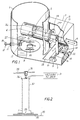
- Figure 1 is a perspective view, partly broken away view of an air flow control system embodiment of the invention affording improved lifting mechanism performance, and
- Figure 2 is a schematic system diagram for illustrating the interacting control features of the invention.
- Now with reference to the drawings, it is seen from Figure 2 that the primary control mechanism 1 for the system may be located in the lower lifting mechanism body portion generally comprising the lowermost cylindrical cap to the expandable and
retractable body portion 30. Its collapsed length is controlled by restricting the air flow into thevacuum source 31 and internal air pressure modifying means for lengthening thebody 30. - The specific control mechanisms of Figure 1 thus control grasping, balancing, lifting, transporting, lowering and releasing the
work load object 32 from or onto awork surface 33, which might be a movable conveyor or a factory floor. Thetransport line 34 typically provides for transport of the liftedwork object 32 to another location by means of riding carriage 35, coupled to anuppermost cap 36 on thelifting mechanism body 30. In operation therefore the differential in pressure inside thelifting mechanism body 30 and the atmosphere as provided by the balancing of thevacuum source 31 with injected atmospheric air will proportion the retraction or foreshortening of the vertically disposed longitudinallift mechanism body 30 to lift thework body objects 32 upwardly off thesurface 33 for transport. Conversely the pressure within thelift body 30 can be returned to substantially atmospheric to lengthen the body and lower the work body objects toward thesurface 33. Both this general type of vacuum powered lifting system operation and accompanying lifting element, vacuum power and transport construction is known in the art and thus need not herein be discussed in greater detail. - Now the construction and operation of the improved body length control system of Figure 1 for introducing variable quantities of atmospheric air flow into the lift body to modify the lower pressure established by the vacuum source as provided by this invention is discussed.
- Atmospheric air enters the
control enclosure 3 through anaccess port 23 and passes into thecontrol valve body 4 where it exits through a critically shaped slottedopening exit port 24. The air exits from thevalve body 4 in the interior of the lift body portion 1 at a generally centrally located position along the body longitudinal axis for optimum effect and to avoid delayed transit time for effectuating control. The longitudinally positionedvalve slot 26 is cut into the side wall of thevalve body 4. A longitudinally movable diaphragm orcontrol valve member 5 opens more or less of the length of slottedexit port 26 to release air by the axial positioning of themember 5 by way of control rod member 6 to move within thevalve body 4 cylinder, or equivalent valve housing. - Control rod 6 is thus reciprocated as represented by the two headed arrow, typically by a human operator supplied with a suitable control handle (not shown). This is a critical operation for controlling the length of the lift mechanism and the grasping, movement and releasing of the work object. In particular control is most critical in the lengthening of the tube to lower and release a work product or to grasp it by increasing the flow of air into the lift body.
- Balancing of the vacuum source contribution and increased pressure due to input atmospheric air is necessary to lower the lifting mechanism for grasping the work body object when unloaded. Also critical is the lowering of a work load object, which must be precisely controlled by increased input air flow to balance the vacuum source contribution for lowering the work load object to deposit it on the work surface. Disproportionate and critical operator control means for this in prior art systems introduced operator concern and tediousness, required critically trained and experienced operators and produced risks of dropping a work load object with potential danger to personnel or equipment or in an improper location. This invention provide the precision proportional control by the operating lever of the length of the lifting mechanism over a substantially linear direction, which is afforded by the shape of the
slot 26 serving asair exit port 24 in the preferred embodiment. - The exit port shape is controlled for the dimensions of the lift body and the vacuum source characteristics in a manner easily determined by those skilled in the art to achieve a substantially linear and proportional control with movement of the control lever 6 in a manner that is uncritical to require little skill and experience from an operator. Other shapes and configurations of this valve structure will become evident from the teachings of this invention.
- It should be evident therefore that this invention provides the operator with means for smooth, progressive and substantially linear control of the length of the lifting mechanism and therefore enables precision placement, grasping, lifting, transport and release of work products in a manner not heretofore feasible with prior art system controls.
- Further features of the invention which relate to the interaction of the pressure control means of this invention with the reaction of the lifting mechanism to produce improved control features and modes not available in the art, include variably adjustable height control means for producing an operator-independent uppermost lifting limit under both the conditions of no-load and full load.
These control means operate to vent variably adjustable minimal magnitudes of flow of air into the lift mechanism body by means of two adjustable venting valves. - Thus the sliding
valve plate 8 is provided to effect a first control function of establishing the predetermined height which the control unit of Fig. 2 will take in the absence of a load. The load supplied by a work load object to be lifted is disposed below thebottom plate 2 and serves to seal thevent 25 when the liftcontrol valve member 4 establishes a reduced pressure by occluding theair vent slot 26. The decreased pressure within the lift mechanism body in essence sucks the surface of the work load object into surface contact. - In accordance with this invention, the
vent valve opening 25 is adjusted to vent in the absence of a work load a predetermined amount of air that will cause the lift mechanism to shorten and raise the control unit 1 to a predetermined height in a normally inactive condition with the vacuum source attached. Thus theknob 12 ofadjustment screw 19 movesadjustment valve plate 8 over a part of the vent opening 25 as permitted by the bolt-slot assembly 20, with the adjustment screw threaded through the housing at 11 to move thevalve flange member 17 reciprocally. The size of theventing aperture 25 is thus controlled so that the unloaded control unit 1 will lift to an established pre-set position and hang there when thelifting valve 5 is in its normally closed inactive position and a work load object is not grasped to seal thevent valve opening 25. Further this structure provides a continuous flow of air in the absence of the work load so that the vent is not sealed. This provides assurance of an immediate grasp of the work load without complicated manipulation of pressure controls or repositioning of thebottom plate 2 as the pressure within the lifting housing is decreased from its highest pressure limit at which the housing is extended at its longest length. The opening size control means also serves through the access port to assure a maximum vacuum sealing grasp for a work object located below thebottom plate 2. - When little or no air passes through the venting
aperture 25 in thebottom plate 2, because a work object is grasped to seal the opening, another mechanism becomes necessary to determine the vertical position attained when thecontrol valve 5 cuts off air flow into the lifting mechanism body and the lowest vacuum pressure level is attained, thereby producing the most retracted lift body length and the highest position that the work load object can attain. Thus thescrew assembly 22 is provided for adjusting a stop position for the control valve operating rod 6 in the normally inactive position attained by means of thebias spring 14 in the absence of active manual or equivalent control movement of the control rod 6. The screw is threaded through theenclosure body 3 to move the pivot arm 7 about the axis ofpivot rod 16 mounted in bearingblocks 9 by means ofbolts 21. Pivot arm 7 is slotted at 15 for movement of the pivot pin in control rod 6 over the arc of movement of the pivot arm 7 and accompanying linear axial movement of control rod 6. - The
screw assembly 22 thus establishes a minimal opening size of the slottedvent port 26 incontrol valve 5 for feeding atmospheric air into the lift mechanism body to prevent a low enough pressure established by the vacuum source to retract the length of the lift mechanism beyond a point establishing a maximum height of the work piece object under load whenport 25 is closed. Thereturn spring 13 is slightly weaker than thebias spring 14 interposed in the adjustment link. Thus, thereturn spring 13 does not cause theslot 26 to be fully opened when the operator releases control rod 6 to let it return to its normal position, with the vacuum source connected. Thus, the length of the lift mechanism is adjusted in that condition by thescrew assembly 22 to determine the maximum height and to assure a minimum pressure limit inside the lift mechanism body from the vacuum source. It is assured then that a loaded lift will attain a predetermined operator-independent height, as well as an unloaded lift, respectively by means of adjustment screws 22 and 19. - In operation therefore the control mechanism of this invention as shown in detail in Figure 2 operates the vacuum powered lifting system in different modes of operation than prior art systems to overcome the deficiencies in the prior art heretofore set forth. The proportional movement of the lift mechanism with the position of the control rod 6 thus gives noncritical control of a load, particularly in the lowering release operation, which has been critical and hard to adjust in prior art vacuum lift systems. Accordingly, as more and more air is injected by the
control valve slot 26 at a critical position along the vertical axis of the lifting mechanism the lift body lengthens to lower a work load object over a distance proportional to the movement of the control rod 6. The operator thus has to have no particular expertise and need not be concerned with critical concentration to operate a valve through a critical and sensitive non-linear region where very small movements of a control lever cause very large changes in interior lift housing pressure as provided in prior art systems. - Furthermore the operator need not be concerned with the operation to attain a preferred height for the work load, or for the
bottom plate 2 of an unloaded lift mechanism by manipulation of the control rod 6, since these uppermost position limits are pre-set by means of adjustment screws 19 and 22. The control range within proper position limits and operational limits of the vacuum system is assured so that the possibility of operator error that could damage equipment or inadvertently drop a work load object is eliminated. - Also because of the grasping structure about
vent 25 inplate 2, adjusted to provide a continuous flow of air to establish a proper grasping pressure at the bottom plate when a work object is not being grasped, assures that there is no condition where a load would not be grasped when the control rod lever 6 is used to close the aircontrol valve slot 26 and permit pressure to decrease within the lift mechanism body for vacuum grasping and lifting the work object. The prior art attempts to prevent any leakage through the grasping structure by valving structure or the like provide the danger of malfunction. - Thus, having provided a vacuum lift system that operates in improved modes eliminating the possibility of operator errors under critical control conditions and providing control of the lifting mechanisms in a non-critical proportional operating mode that requires little operator expertise, those novel features defining the invention are set forth in the following claims.
Claims (5)
- A vacuum powered lifting system having a vacuum source (31), a variable length lifting mechanism housing (30) coupled to the vacuum source to vary in length as a function of differential pressure from atmospheric within the housing (30), load coupling means (2, 25) to couple the lifting mechanism to a work load object for lifting and transport by reduced pressure from the vacuum source, differential pressure control means (1) for introducing atmospheric air into the housing (30) for controlling the length of the housing (30), and a manually movable control member (6) operable to control the magnitude of a flow of said atmospheric air into said housing,
an air dispensing valve (4, 5) controlled by said control member (6) to change with the length of manual movement of the control member (6) over a specified control range of working length of the housing (30) the magnitude of atmospheric air in the housing (30) thereby to change the corresponding length of the housing substantially proportionately to the length of manual movement of the control member (6),
characterized by:
an air vent slot (26) and variable control valve member (5) for occluding air through the air vent slot (26) being movable along the air vent slot (26) by control member (6) disposed in said air dispensing valve (4, 5) for controlling the magnitude of atmospheric air entering the housing (30) thereby to proportionately change the length of the housing (30) with the magnitude of movement of the control member (6). - Lifting system according to claim 1, further characterized by:
height control means (22, 7, 13, 15) for establishing a normal position of said control member when not variably controlled manually by an operator for establishing a low enough pressure in said housing (30) from the vacuum source (31) to establish a maximum height of the work piece object (32) under load when the vent slot (26) is occluded by the control members (5, 6) in a maximum lift position within said control range. - Lifting system according to one of the foregoing claims, further characterized by:
height adjusting valve means (8, 11, 12, 19, 20) for establishing the length of the housing (30) under no-load conditions. - Lifting system according to one of the foregoing claims, further characterized by:
an object grasping surface (2) for establishing an air flow communication between the differential pressure in said housing (30) and a surface of the load object (32) when the control member (6) is positioned to lift a load providing therein a normally open air flow input port (25) on the grasping surface (2) for continuously introducing a flow of air into the body when a work object (32) is not grasped. - Lifting system according to claim 4, further characterized by:
adjustable control means (8, 11, 12, 19, 20) operable with said air flow input port (25) for establishing a predetermined height the housing assumes in the absence of a load (32).
Priority Applications (2)
| Application Number | Priority Date | Filing Date | Title |
|---|---|---|---|
| AT91106132T ATE127766T1 (en) | 1991-04-17 | 1991-04-17 | VACUUM CONTROL SYSTEM FOR LIFTING EQUIPMENT. |
| DE1991613021 DE69113021T2 (en) | 1991-04-17 | 1991-04-17 | Vacuum control system for lifting devices. |
Applications Claiming Priority (1)
| Application Number | Priority Date | Filing Date | Title |
|---|---|---|---|
| US07/500,969 US5035456A (en) | 1990-03-29 | 1990-03-29 | Vacuum control system for lifting systems |
Publications (2)
| Publication Number | Publication Date |
|---|---|
| EP0509115A1 EP0509115A1 (en) | 1992-10-21 |
| EP0509115B1 true EP0509115B1 (en) | 1995-09-13 |
Family
ID=23991622
Family Applications (1)
| Application Number | Title | Priority Date | Filing Date |
|---|---|---|---|
| EP91106132A Expired - Lifetime EP0509115B1 (en) | 1990-03-29 | 1991-04-17 | Vacuum control system for lifting systems |
Country Status (3)
| Country | Link |
|---|---|
| US (1) | US5035456A (en) |
| EP (1) | EP0509115B1 (en) |
| CA (1) | CA2038775A1 (en) |
Cited By (1)
| Publication number | Priority date | Publication date | Assignee | Title |
|---|---|---|---|---|
| DE102020128380A1 (en) | 2020-10-28 | 2022-04-28 | AERO-LIFT Vakuumtechnik Gesellschaft mit beschränkter Haftung | tube lifter |
Families Citing this family (11)
| Publication number | Priority date | Publication date | Assignee | Title |
|---|---|---|---|---|
| US5035456A (en) * | 1990-03-29 | 1991-07-30 | Robert Messinger | Vacuum control system for lifting systems |
| GB9100056D0 (en) * | 1991-01-03 | 1991-02-20 | Palamatic Handling Syst | Valve arrangement |
| US5221117A (en) * | 1992-04-30 | 1993-06-22 | Messinger Robert A | Fully rotatable vacuum lift with self contained utility lines |
| JP2826045B2 (en) * | 1992-10-02 | 1998-11-18 | 株式会社キトー | Vacuum lift device |
| US5816635A (en) * | 1994-07-26 | 1998-10-06 | Ljungblad-Petre Maskin Ab | Chock valve for a vacuum lifting device |
| DE19614479C1 (en) * | 1996-04-12 | 1997-07-24 | Schmalz J Gmbh | Vacuum-operated manipulator |
| DE10038013B4 (en) * | 2000-08-04 | 2005-11-03 | Albert Fezer Maschinenfabrik Gmbh | Control device for a vacuum lifting device |
| CN108349093B (en) * | 2015-09-08 | 2022-01-14 | 伯克希尔格雷股份有限公司 | System and method for providing dynamic vacuum pressure in an articulated arm end effector |
| US10814498B2 (en) | 2017-11-07 | 2020-10-27 | Berkshire Grey, Inc. | Systems and methods for providing dynamic vacuum pressure at an end effector using a single vacuum source |
| EP4247599B1 (en) | 2020-11-19 | 2025-08-20 | Berkshire Grey Operating Company, Inc. | Systems and methods for object processing using grippers for objects with low pose authority |
| DE102022132993A1 (en) * | 2022-12-12 | 2024-06-13 | Timmer Gmbh | Vacuum lifting device |
Citations (1)
| Publication number | Priority date | Publication date | Assignee | Title |
|---|---|---|---|---|
| US5035456A (en) * | 1990-03-29 | 1991-07-30 | Robert Messinger | Vacuum control system for lifting systems |
Family Cites Families (14)
| Publication number | Priority date | Publication date | Assignee | Title |
|---|---|---|---|---|
| GB376110A (en) * | 1931-10-05 | 1932-07-07 | Fritz Neuenschwander | Lifting tackle, for cranes with crabs |
| FR87687E (en) * | 1964-04-22 | 1966-09-23 | Staubli Freres & Cie | Axial Flow Flow Control Valve Improvements |
| DE1431936A1 (en) * | 1965-11-13 | 1969-04-24 | Hasenclever Ag Maschf | Device for lifting and lowering loads |
| FR1474799A (en) * | 1965-12-30 | 1967-03-31 | Bertin & Cie | Load-carrying suction cup device |
| US3558171A (en) * | 1967-11-15 | 1971-01-26 | Netzsch Maschinenfabrik | Pneumatic arrangement for transferring articles |
| DE1924293B2 (en) * | 1969-05-13 | 1972-01-27 | Demag Ag, 4100 Duisburg | SUCTION HEAD FOR SOLID BODY |
| CH526461A (en) * | 1971-02-10 | 1972-08-15 | Gis Ag | Vacuum lifting device |
| FR2370660A1 (en) * | 1976-11-12 | 1978-06-09 | Thierion Michel | Vacuum pad for lifting bottles - has sprung valve with operating lever actuated by presence of bottle |
| US4397331A (en) * | 1978-09-29 | 1983-08-09 | Honeywell Inc. | Fluid flow control valve with maximized noise reduction |
| US4266905A (en) * | 1979-04-20 | 1981-05-12 | Board Of Regents For Education Of The State Of Rhode Island | Apparatus for acquiring workpieces from a storage bin or the like |
| SE446621B (en) * | 1980-02-04 | 1986-09-29 | Sten Andersson | Vacuum lifting device for goods or other objects |
| US4384592A (en) * | 1980-11-28 | 1983-05-24 | International Telephone And Telegraph Corporation | Low-noise valve trim |
| GB2200615A (en) * | 1987-01-22 | 1988-08-10 | Portec Inc | Suction actuated lifting apparatus |
| GB8828914D0 (en) * | 1988-12-10 | 1989-01-18 | Palamatic Handling Syst | Vacuum lifting apparatus |
-
1990
- 1990-03-29 US US07/500,969 patent/US5035456A/en not_active Expired - Lifetime
-
1991
- 1991-03-27 CA CA002038775A patent/CA2038775A1/en not_active Abandoned
- 1991-04-17 EP EP91106132A patent/EP0509115B1/en not_active Expired - Lifetime
Patent Citations (1)
| Publication number | Priority date | Publication date | Assignee | Title |
|---|---|---|---|---|
| US5035456A (en) * | 1990-03-29 | 1991-07-30 | Robert Messinger | Vacuum control system for lifting systems |
Cited By (3)
| Publication number | Priority date | Publication date | Assignee | Title |
|---|---|---|---|---|
| DE102020128380A1 (en) | 2020-10-28 | 2022-04-28 | AERO-LIFT Vakuumtechnik Gesellschaft mit beschränkter Haftung | tube lifter |
| EP3992135A1 (en) | 2020-10-28 | 2022-05-04 | AERO-LIFT Vakuumtechnik GmbH | Hose lifter |
| DE102020128380B4 (en) | 2020-10-28 | 2023-01-05 | AERO-LIFT Vakuumtechnik Gesellschaft mit beschränkter Haftung | tube lifter |
Also Published As
| Publication number | Publication date |
|---|---|
| US5035456A (en) | 1991-07-30 |
| EP0509115A1 (en) | 1992-10-21 |
| CA2038775A1 (en) | 1991-09-30 |
Similar Documents
| Publication | Publication Date | Title |
|---|---|---|
| EP0509115B1 (en) | Vacuum control system for lifting systems | |
| EP0309987B1 (en) | Fluid pressure control system | |
| US5456130A (en) | Load balancing arm | |
| EP1019315B2 (en) | Productivity package | |
| US8105008B2 (en) | Pneumatic multi-weight balancing device | |
| CN100408468C (en) | For use in control systems in load handling equipment | |
| US3599262A (en) | Attitude sensing system for use during loading and unloading of vehicles | |
| US3734325A (en) | Safety interlock for fluid-operated, load-handling apparatus | |
| US3259352A (en) | Loading balancer assembly | |
| CN101027244A (en) | Material handling vehicles including electrically controlled valves | |
| US4421450A (en) | Cargo handling apparatus | |
| US6370970B1 (en) | Cargo handling machine including force control | |
| CN111731998B (en) | A position control system of movable counterweight block for rock removal machine | |
| US2659505A (en) | Mechanism for controlling the stability of material-handling machines | |
| CA2594269C (en) | Pneumatic multi-weight balancing device | |
| US4462571A (en) | Fluid-operated, load-handling apparatus | |
| KR20040031063A (en) | Hydraulic powered arm system with float control | |
| CN218453616U (en) | Blanking flow control device | |
| US8702369B2 (en) | Load sensing device for manipulators and balancers | |
| JP2654748B2 (en) | Automatic weight sensing balance lifting device | |
| JP3116601B2 (en) | Forklift control device | |
| JP3787056B2 (en) | Safety device for high-altitude work equipment | |
| JPH05213589A (en) | Side shifting device for forklift | |
| EP4556424A1 (en) | Pneumatic elevator with pressure regulator | |
| JPH0649594Y2 (en) | Speed control device for cargo handling equipment |
Legal Events
| Date | Code | Title | Description |
|---|---|---|---|
| PUAI | Public reference made under article 153(3) epc to a published international application that has entered the european phase |
Free format text: ORIGINAL CODE: 0009012 |
|
| AK | Designated contracting states |
Kind code of ref document: A1 Designated state(s): AT BE CH DE DK ES FR GB IT LI NL SE |
|
| 17P | Request for examination filed |
Effective date: 19930405 |
|
| 17Q | First examination report despatched |
Effective date: 19940218 |
|
| GRAA | (expected) grant |
Free format text: ORIGINAL CODE: 0009210 |
|
| AK | Designated contracting states |
Kind code of ref document: B1 Designated state(s): AT BE CH DE DK ES FR GB IT LI NL SE |
|
| PG25 | Lapsed in a contracting state [announced via postgrant information from national office to epo] |
Ref country code: IT Free format text: LAPSE BECAUSE OF FAILURE TO SUBMIT A TRANSLATION OF THE DESCRIPTION OR TO PAY THE FEE WITHIN THE PRESCRIBED TIME-LIMIT;WARNING: LAPSES OF ITALIAN PATENTS WITH EFFECTIVE DATE BEFORE 2007 MAY HAVE OCCURRED AT ANY TIME BEFORE 2007. THE CORRECT EFFECTIVE DATE MAY BE DIFFERENT FROM THE ONE RECORDED. Effective date: 19950913 Ref country code: BE Effective date: 19950913 Ref country code: CH Effective date: 19950913 Ref country code: NL Free format text: LAPSE BECAUSE OF FAILURE TO SUBMIT A TRANSLATION OF THE DESCRIPTION OR TO PAY THE FEE WITHIN THE PRESCRIBED TIME-LIMIT Effective date: 19950913 Ref country code: AT Effective date: 19950913 Ref country code: LI Effective date: 19950913 Ref country code: ES Free format text: THE PATENT HAS BEEN ANNULLED BY A DECISION OF A NATIONAL AUTHORITY Effective date: 19950913 Ref country code: DK Effective date: 19950913 |
|
| REF | Corresponds to: |
Ref document number: 127766 Country of ref document: AT Date of ref document: 19950915 Kind code of ref document: T |
|
| REF | Corresponds to: |
Ref document number: 69113021 Country of ref document: DE Date of ref document: 19951019 |
|
| PG25 | Lapsed in a contracting state [announced via postgrant information from national office to epo] |
Ref country code: SE Effective date: 19951213 |
|
| EN | Fr: translation not filed | ||
| REG | Reference to a national code |
Ref country code: CH Ref legal event code: PL |
|
| NLV1 | Nl: lapsed or annulled due to failure to fulfill the requirements of art. 29p and 29m of the patents act | ||
| EN | Fr: translation not filed |
Free format text: BO 96/06 PAGES 200 IL Y A LIEU DE SUPPRIMER:LA MENTION DE LA NON REMISE DE LA TRADUCTION |
|
| ET | Fr: translation filed | ||
| PLBE | No opposition filed within time limit |
Free format text: ORIGINAL CODE: 0009261 |
|
| STAA | Information on the status of an ep patent application or granted ep patent |
Free format text: STATUS: NO OPPOSITION FILED WITHIN TIME LIMIT |
|
| 26N | No opposition filed | ||
| PGFP | Annual fee paid to national office [announced via postgrant information from national office to epo] |
Ref country code: FR Payment date: 20000411 Year of fee payment: 10 |
|
| PGFP | Annual fee paid to national office [announced via postgrant information from national office to epo] |
Ref country code: GB Payment date: 20000412 Year of fee payment: 10 |
|
| PGFP | Annual fee paid to national office [announced via postgrant information from national office to epo] |
Ref country code: DE Payment date: 20000417 Year of fee payment: 10 |
|
| PG25 | Lapsed in a contracting state [announced via postgrant information from national office to epo] |
Ref country code: GB Free format text: LAPSE BECAUSE OF NON-PAYMENT OF DUE FEES Effective date: 20010417 |
|
| PG25 | Lapsed in a contracting state [announced via postgrant information from national office to epo] |
Ref country code: FR Free format text: THE PATENT HAS BEEN ANNULLED BY A DECISION OF A NATIONAL AUTHORITY Effective date: 20010430 |
|
| GBPC | Gb: european patent ceased through non-payment of renewal fee |
Effective date: 20010417 |
|
| PG25 | Lapsed in a contracting state [announced via postgrant information from national office to epo] |
Ref country code: DE Free format text: LAPSE BECAUSE OF NON-PAYMENT OF DUE FEES Effective date: 20020201 |
|
| REG | Reference to a national code |
Ref country code: FR Ref legal event code: ST |