EP0508599B1 - Treiber für ein piezoelektrisches Stellglied und Kontrollvorrichtung für den Verschluss, die eine piezoelektrische Vorrichtung benutzt - Google Patents
Treiber für ein piezoelektrisches Stellglied und Kontrollvorrichtung für den Verschluss, die eine piezoelektrische Vorrichtung benutzt Download PDFInfo
- Publication number
- EP0508599B1 EP0508599B1 EP92302057A EP92302057A EP0508599B1 EP 0508599 B1 EP0508599 B1 EP 0508599B1 EP 92302057 A EP92302057 A EP 92302057A EP 92302057 A EP92302057 A EP 92302057A EP 0508599 B1 EP0508599 B1 EP 0508599B1
- Authority
- EP
- European Patent Office
- Prior art keywords
- voltage
- piezoelectric actuator
- engagement
- leading
- laminate piezoelectric
- Prior art date
- Legal status (The legal status is an assumption and is not a legal conclusion. Google has not performed a legal analysis and makes no representation as to the accuracy of the status listed.)
- Expired - Lifetime
Links
Images


Classifications
-
- H—ELECTRICITY
- H02—GENERATION; CONVERSION OR DISTRIBUTION OF ELECTRIC POWER
- H02N—ELECTRIC MACHINES NOT OTHERWISE PROVIDED FOR
- H02N2/00—Electric machines in general using piezoelectric effect, electrostriction or magnetostriction
- H02N2/02—Electric machines in general using piezoelectric effect, electrostriction or magnetostriction producing linear motion, e.g. actuators; Linear positioners ; Linear motors
- H02N2/06—Drive circuits; Control arrangements or methods
-
- G—PHYSICS
- G03—PHOTOGRAPHY; CINEMATOGRAPHY; ANALOGOUS TECHNIQUES USING WAVES OTHER THAN OPTICAL WAVES; ELECTROGRAPHY; HOLOGRAPHY
- G03B—APPARATUS OR ARRANGEMENTS FOR TAKING PHOTOGRAPHS OR FOR PROJECTING OR VIEWING THEM; APPARATUS OR ARRANGEMENTS EMPLOYING ANALOGOUS TECHNIQUES USING WAVES OTHER THAN OPTICAL WAVES; ACCESSORIES THEREFOR
- G03B7/00—Control of exposure by setting shutters, diaphragms or filters, separately or conjointly
- G03B7/08—Control effected solely on the basis of the response, to the intensity of the light received by the camera, of a built-in light-sensitive device
- G03B7/10—Control effected solely on the basis of the response, to the intensity of the light received by the camera, of a built-in light-sensitive device a servo-motor providing energy to move the setting member
-
- G—PHYSICS
- G03—PHOTOGRAPHY; CINEMATOGRAPHY; ANALOGOUS TECHNIQUES USING WAVES OTHER THAN OPTICAL WAVES; ELECTROGRAPHY; HOLOGRAPHY
- G03B—APPARATUS OR ARRANGEMENTS FOR TAKING PHOTOGRAPHS OR FOR PROJECTING OR VIEWING THEM; APPARATUS OR ARRANGEMENTS EMPLOYING ANALOGOUS TECHNIQUES USING WAVES OTHER THAN OPTICAL WAVES; ACCESSORIES THEREFOR
- G03B9/00—Exposure-making shutters; Diaphragms
- G03B9/08—Shutters
- G03B9/10—Blade or disc rotating or pivoting about axis normal to its plane
- G03B9/18—More than two members
-
- H—ELECTRICITY
- H02—GENERATION; CONVERSION OR DISTRIBUTION OF ELECTRIC POWER
- H02N—ELECTRIC MACHINES NOT OTHERWISE PROVIDED FOR
- H02N2/00—Electric machines in general using piezoelectric effect, electrostriction or magnetostriction
- H02N2/02—Electric machines in general using piezoelectric effect, electrostriction or magnetostriction producing linear motion, e.g. actuators; Linear positioners ; Linear motors
- H02N2/04—Constructional details
- H02N2/043—Mechanical transmission means, e.g. for stroke amplification
-
- H—ELECTRICITY
- H02—GENERATION; CONVERSION OR DISTRIBUTION OF ELECTRIC POWER
- H02N—ELECTRIC MACHINES NOT OTHERWISE PROVIDED FOR
- H02N2/00—Electric machines in general using piezoelectric effect, electrostriction or magnetostriction
- H02N2/02—Electric machines in general using piezoelectric effect, electrostriction or magnetostriction producing linear motion, e.g. actuators; Linear positioners ; Linear motors
- H02N2/06—Drive circuits; Control arrangements or methods
- H02N2/065—Large signal circuits, e.g. final stages
- H02N2/067—Large signal circuits, e.g. final stages generating drive pulses
Definitions
- the present invention relates to a piezoelectric actuator adapted for use in a camera and a shutter control device utilizing piezoelectric device.
- So-called piezoelectric actuator is a piezoelectric device used to convert an electrical signal into a mechanical displacement.
- Such piezoelectric device consists of a stack of a plurality of thin ceramic plates having piezoelectric property, and, upon application of a voltage in the order of 100 V between two electrodes, shows a dimensional change by expansion or contraction depending on the polarity of said voltage.
- the piezoelectric actuator with the above-mentioned features is utilized for driving a mechanical system, utilizing its expansion or contraction occurring between a state of no voltage application and a state of rated voltage application, but the available displacement and acceleration are limited and insufficient for a general driving source for mechanical systems.
- piezoelectric actuator is associated with a drawback of slow response, as it takes a certain time from the voltage application to the completion of displacement because of its mechanical inertia.
- such piezoelectric actuator constituting a capacitor in the equivalent circuit, absorbs a large current at the start of voltage application, and this current further increases and elevates the power consumption if the applied voltage is elevated in order to increase the amount of displacement.
- the application of such piezoelectric actuator in a camera may reduce the service life of the battery therein, as the camera already includes large electric loads such as electronic flash unit and light source for illuminating liquid crystal display.
- the piezoelectric actuator employed in the camera cannot function properly even under the rated voltage application because of an excessive load, if the functioning direction of the actuator is opposite to the direction of gravity.
- the above-explained piezoelectric actuator has a drawback of being susceptible to humidity.
- the piezoelectric actuator is usually hermetically sealed with resin in order to exclude moisture, but the distance between the electrodes formed on both surfaces becomes small because of the multi-layered structure of thin ceramic plates and the insulation may be destructed by the voltage application in the order of 100 V under a high humidity condition. Such destruction of insulation may be temporary, but is in most cases permanent, whereby the piezoelectric actuator itself is destructed.
- the piezoelectric actuator employed therein is subjected to the same condition, and may cause destruction of insulation by humidity. This failure of the piezoelectric actuator is only noticed by the absence of start of an exposure operation when the user depresses the shutter button, so that he will lose the opportunity of phototaking.
- piezoelectric actuator is associated with various drawbacks which are related to a pyroelectric effect it usually exhibits.
- Said pyroelectric effect means a phenomenon of a voltage generation in the piezoelectric actuator by the infrared light or thermal radiation entering the actuator from the atmosphere.
- the piezoelectric actuator When employed in a camera, the piezoelectric actuator generates a DC voltage between the electrodes thereof by said pyroelectric effect, by absorbing heat from the surrounding atmosphere in spontaneous manner, even while the voltage application by the depression of shutter button is not conducted. Although said voltage generation is gradual, it increases with time, thereby hindering proper function of the piezoelectric actuator at the voltage application thereto for a shutter releasing operation. If the voltage generated by the pyroelectric effect is same in polarity as the applied voltage, there will result an excessively large voltage, eventually leading to the destruction of piezoelectric actuator or undesirable effect on the associated electrical circuits. On the other hand, if the voltage resulting from the pyroelectric effect is opposite in polarity to the applied voltage, there will result an insufficient applied voltage.
- the piezoelectric device in the actuator having reversible characteristics, causes a mechanical displacement in response to a voltage application, and also generates a voltage when a mechanical pressure is applied from the outside. Because of this property, if the camera is given a mechanical shock or is dropped, a mechanical impact is given to the piezoelectric actuator to generate a large spike voltage, which flows to the associated circuits, thereby inducing destruction thereof or giving a noise to delicate control circuits.
- a conceivable application of the piezoelectric actuator is the shutter control device, for controlling the shutter time of a focal plane shutter or the like.
- shutter control devices there is already known for example, a device disclosed in the Japanese Utility Model Laid-open Application No. 64-34621, comprising a solenoid device, an armature member to be attracted by said solenoid device, a biasing member for biasing said armature member in a direction for releasing said member from said solenoid device, and a resetting member for driving said armature member toward the solenoid device against the force of said biasing member, all being provided in a pair, wherein the function of a camera is controlled by a movement of releasing the armature member from the solenoid device.
- the present invention provides apparatus for controlling the exposure time of a shutter by first releasing the engagement on a leading curtain and, after the lapse of a predetermined time, releasing the engagement on a trailing curtain, comprising:
- a control device can be provided which is free of defective armature attraction or of delayed operation of the armature lever.
- Such a device owing to the use of piezoelectric devices, is capable of preventing drawbacks such as shutter malfunction resulting from defective solenoid attraction or fluctuation in exposure time resulting from linking in the conventional mechanisms.
- a shutter control device capable of securely obtaining driving force with a transmission member from even a small deformation of the laminate piezoelectric device, thereby avoiding malfunction of the shutter.
- a shutter control mechanism for controlling the exposure time by at first releasing the engagement on a leading curtain, and after the lapse of a predetermined time, releasing the engagement on a trailing curtain, comprising:
- a further point is that, since the laminate piezoelectric device shows only a deformation in the order of 0.01 mm, in some designs there might not be provided a sufficient distance in the above-mentioned device, between the members for engaging with the leading and trailing curtains and the members for driving said curtains after the engagements thereon are released, so that the exposure time may fluctuate by eventual collision of the curtain driving members with the engaging members in the course of returning to the engaging positions after the release of engagement. Therefore, another preferred embodiment provides a shutter control device capable of securely preventing the collision of the engaging member for the leading and trailing curtains with the driving members therefor, by means of a simple mechanism, within a limited space, thereby eliminating the fluctuation in the shutter time.
- a shutter control mechanism for controlling the exposure time by at first releasing the engagement on a leading curtain and, after the lapse of a predetermined time, releasing the engagement on a trailing curtain, comprising:
- returning inhibition members for inhibiting the engaging members from returning to the engaging positions after they are released from engagement, thereby avoiding the collision of said engaging members with the driving members for the leading and trailing curtains. Therefore the leading and trailing curtains are maintained free from perturbations after the start of their motions, so that the drawbacks such as the fluctuation in the shutter time can be provided.
- the piezoelectric actuator can provide a large displacement with a low electric power consumption.
- a driver for a piezoelectric actuator comprises:
- the piezoelectric actuator is at first displaced in a direction opposite to the functioning direction by the application of a voltage of inverse polarity, and is then displaced in the functioning direction by the application of a forward voltage. Since the displacement of the piezoelectric actuator starts a position in the opposite direction, the acceleration becomes larger than in the conventional actuator, and the amount of displacement also becomes larger.
- a driver for the piezoelectric actuator enables secure function under various conditions.
- a driver for a piezoelectric actuator comprises:
- the completion of function of the mechanical means can be further secured by making the re-applied voltage her than the previously applied voltage.
- Another preferred feature of the present invention is the prevention of the destruction of insulation in the piezoelectric actuator under the influence of humidity, etc.
- a driver for piezoelectric actuator comprises:
- a modification of said driver further comprises alarm means for effecting an alarm providing function in case the insulation detection means identifies that the electrical insulation state of the piezoelectric actuator has been deteriorated.
- the insulation state can be detected, for example, by applying a current to the piezoelectric actuator and comparing the resulting voltage drop with a predetermined value. If the insulation state is deteriorated, the internal resistance of the piezoelectric actuator becomes lower, whereby the generated voltage drop becomes lower than the predetermined value.
- a driver for piezoelectric actuator comprises:
- a driver for piezoelectric actuator comprises:
- these drivers for piezoelectric actuator identify whether the piezoelectric actuator may cause destruction of insulation, by detecting the insulation state of the piezoelectric actuator or the ambient humidity thereof, and prevent the destruction of insulation by inhibiting the voltage application to the piezoelectric actuator and/or providing an alarm, in case such destruction of insulation is identified possible.
- a driver for a piezoelectric actuator is capable of reducing humidity if the ambient humidity of the piezoelectric actuator is high and may induce destruction of insulation thereof.
- a driver for a piezoelectric actuator comprises:
- the ambient humidity of the piezoelectric actuator is detected by the humidity detection means and is discriminated by the humidity discrimination means as to whether said humidity is higher than a limit humidity that may induce destruction of insulation of the actuator. If the detected humidity is of a level that may induce destruction of insulation, there is given an alarm and the function of the mechanical system is inhibited. Then the voltage generated by the voltage generation means is applied to the piezoelectric actuator, thereby generating heat inside the actuator, by the repetition of charging and discharging by the actuator itself, and the function of the mechanical system is enabled after the moisture absorbed in the actuator is removed. It is thus rendered possible to prevent permanent destruction of the piezoelectric actuator by function thereof under a high humidity condition.
- a driver for a piezoelectric actuator is capable of absorbing the voltage generated therein by pyroelectric effect.
- a driver for a piezoelectric actuator comprises:
- the shortcircuiting of the electrodes of the piezoelectric actuator allows to eliminate the high voltage generated by the pyroelectric effect.
- a driver a for piezoelectric actuator can absorb the voltage generated by the pyroelectric effect or by a mechanical impact applied to the piezoelectric actuator.
- a driver for a piezoelectric actuator comprises:
- Said driver can prevent failure in function or destruction of the electrical circuits, since, if a high voltage is generated between the electrodes of the piezoelectric actuator for example by an impact, the surge absorber is shortcircuited to absorb said voltage.
- Another preferred feature of the present invention is that the driver improves the normal response of the piezoelectric actuator.
- a driver for a piezoelectric actuator comprises:
- the second voltage generation means generates a voltage which causes a small vibration of the piezoelectric actuator with a frequency in the vicinity of the mechanical resonance point thereof.
- the piezoelectric actuator can be utilized in a small equipment such as a camera, as a device for converting a voltage into a mechanical displacement.
- a small equipment such as a camera
- An example of the application of the piezoelectric actuator in a shutter mechanism of a camera is illustrated in Fig. 23 (not part of the present invention), wherein an actuator 201 is used for controlling the start of opening of a leading curtain 220 of the shutter.
- Fig. 23 illustrates a state prior to the opening of the leading curtain.
- the piezoelectric actuator 201 fixed to a fixing member 202, impinges on an end 06 of a lever 203, which is rendered rotatable about a shaft 204 and is biased by a spring 205.
- the lever 203 is provided with a downward pin 207, which is in contact with an end 212 of a lever 209, which is rendered rotatable about a shaft 210 and is biased by a spring 211.
- the lever 209 is provided with a downwards folded end portion 213, in contact with an with an end 217 of a lever 214 which is biased by a spring 216 and directly controls the function of a leading curtain 220.
- Said lever 214 is provided with a pin 218 thereunder, and is rendered rotatable about a shaft 215.
- the leading curtain covers an image frame 221 represented by a broken line.
- the leading curtain 220 moves like a pantagraph, thus exposing the image frame 221.
- the structure of said leading curtain 221 will not be explained in detail, since it is already known.
- the exposure operation, by the control of the leading curtain 220, is conducted in the following manner.
- the piezoelectric actuator 201 extends to upper right, pressing the end 206 of the lever 203, which thus rotates clockwise about the shaft 204, against the force of the spring 205.
- the lever 209 rotates anticlockwise against the force of the spring 211. Since the end 213 of the lever 209, impinging on the end 217 of the lever 214, also rotates anticlockwise, said lever 214 rotates anticlockwise about the shaft 215 by the force of the spring 216, whereby the pin 218 moves to upper right.
- the leading curtain 220 moves also to upper right, thus starting the exposure operation.
- a pin 222 provided on the lever 214 pushes and turns on a limit switch.
- a signal from said limit switch indicates the secure completion of opening of the leading curtain 220, and is utilized, for example, for triggering an electronic flash unit.
- the shutter mechanism of camera requires separate detection means for example for confirming the completion of shutter operation, and inexpensive limit switches are employed for this purpose in most cases.
- another preferred feature of the present invention is a configuration is used which is capable of dispensing with the above-mentioned limit switches, by utilizing the piezoelectric actuator not only as an actuator but also as a sensor.
- the piezoelectric actuator can be used as a sensor, by utilizing its property to generate a voltage between the electrodes, when an impact is applied from the outside.
- a driver for a piezoelectric actuator comprises:
- mechanical means utilizing a piezoelectric actuator is combined with another mechanical means for applying an impact force to said piezoelectric actuator, whereby a signal representing the completion of function of the first-mentioned mechanical means, for example a detection signal for confirming the completion of function, can be obtained from the same actuator. It is therefore rendered possible to reduce the number of components in the detecting device, and to prevent malfunctions in the contacts of detecting device.
- the shutter control mechanism has a reduced power consumption by the use of a piezoelectric device.
- the shutter control device provided with shutter means for effecting an exposure operation and adapted for controlling the function of said shutter means, comprises:
- the shutter control device is capable of reliable shutter operation through the use of a piezoelectric device.
- the shutter control device provided with shutter means for effecting an exposure operation and adapted to control the function of said shutter means, comprising:
- Figs. 1 to 14 illustrate a first embodiment of the present invention, wherein:
- Fig. 2 is a view of a mechanical configuration when a piezoelectric actuator is employed for driving a shutter of a camera.
- piezoelectric actuators 1, 2 are respectively used for driving a leading curtain 17 and a trailing curtain 37 of a shutter, and there is illustrated a state prior to the function of the leading curtain.
- a piezoelectric actuator 1 is fixed to a fixing member 3, and a level 4 biased by a spring 5 is maintained in contact with an end face of the actuator 1.
- Said lever 4 is rendered rotatable, with a pin 7 provided thereon, about a shaft 6.
- a lever 8 rotatable about a shaft 9 and biased by a spring 10, is engageable at an end with said pin 7 and hinders the rotation of a lever 11, which is rotatable about a shaft 13 and biased by a spring 12 but is normally prevented from rotation by an end of said lever 8.
- a pin 14 is provided on the lever 11 for directly controlling the function of a leading shutter curtain 17 which covers an unrepresented film plane in a known manner.
- the pin 14 is provided thereon with a lever 15 in a position capable of turning on and off a switch 16, which is turned off in the illustrated position.
- Another piezoelectric actuator 2 is fixed to a fixing member 23, and a lever 24 biased by a spring 25 is maintained in contact with an end face of the actuator 2.
- Said lever 24 is rendered rotatable, with a pin 27 provided thereunder, about a shaft 26.
- a lever 28, rotatable about a shaft 29 and biased by a spring 30, is engageable at an end with said pin 27 and hinders the rotation of a lever 31, which is rotatable about a shaft 33 and biased by a spring 32 but is normally prevented from rotation by an end of said lever 28.
- a pin 34 is provided on the lever 31 for directly controlling the function of a trailing shutter curtain 37 which is retracted from an unrepresented film plane in a known manner.
- the pin 34 is provided, at an end thereof, with a lever 35 for turning on and off a switch 36, which is turned off in the illustrated position.
- the exposure operation is conducted in the following manner, by the control of the leading and trailing shutter curtains 17, 37.
- the piezoelectric actuator 1 when energized, extends toward upper right, and this displacement with the resulting acceleration is transmitted to the lever 4.
- the lever 4 rotates clockwise against the force of the spring 5, whereby the pin 7 presses an end of the lever 8, thereby causing said lever 8 to rotate anticlockwise about the shaft 9 against the force of the spring 10.
- the piezoelectric actuator 2 is energized, whereupon said actuator 2 extends toward upper left and the resulting displacement is transmitted to the lever 24.
- the lever 24 rotates anticlockwise about the shaft 26 against the biasing force of the spring 25, whereby the pin 27 presses an end of the lever 28, thus causing the lever 28 to rotate clockwise about the shaft 29 against the force of the spring 30.
- Fig. 1 is a block diagram of an electrical circuit for driving the mechanism shown in Fig. 1. The function of said circuit will be explained in the following.
- a battery 40 powers power supply circuits P1, P2, P3.
- the power supply circuit P1 releases an output voltage of about 5V, for a control circuit including a CPU.
- the power supply circuit P2 releases an output voltage of about 100 V for driving the piezoelectric actuators 1, 2 in the normal state and also for driving a display illumination lamp 43.
- the power supply circuit P3 releases an output voltage of about 200 V for driving the piezoelectric actuators 1, 2 in an abnormal state, and also driving a strobe discharge tube 44.
- the function of the power supply circuit P1 is controlled by a half-stroke switch 41 which is to be turned on by the actuation of an unrepresented shutter button of the camera, and by the on-state of a transistor Q1 controlled by the CPU.
- the state of the half-stroke switch 41 is also transmitted to the CPU.
- a diode Q1 is inserted between the transistor Q1 and the half-stroke switch 41 in order to distinguish the on-states thereof. In such configuration, after the half-stroke switch 41 is turned off by the termination of actuation of the shutter button, the transistor 41 remains turned on for a predetermined period, thereby extending the function state of the camera.
- the above-explained configuration is known in the prior art.
- the function of the power supply circuits P2, P3 is controlled respectively by transistors Q2, Q3 which are in turn controlled by the CPU.
- circuit blocks including a light metering circuit LM, a display circuit DSP, an aperture control circuit AP, a film sensitivity signal reading circuit FM, a humidity detection circuit HMD and a group of switches SW, which have the following input/output functions.
- the light metering circuit LM enters an object luminance signal to the CPU.
- the display circuit DSP provides shutter time information to be controlled and various alarm signals, in visual or acoustic manner, based on signals from the CPU.
- the aperture control circuit AP controls a lens diaphragm to an appropriate aperture, based on a signal from the CPU.
- the film sensitivity signal reading circuit FM reads film sensitivity data, provided on a film cartridge in a known manner, and sends said data to the CPU.
- the humidity detection circuit HMD detects the humidity in the camera with a humidity sensor and sends a corresponding signal to the CPU.
- the humidity sensor may be provided in a position allowing identify the humidity of the piezoelectric actuator provided in the camera. Ideally it is adhered to the piezoelectric sensor, in order to enable precise humidity detection.
- the switch group SW includes a release switch linked with the shutter button and instructing the start of exposure operation, : switch for detecting the completion of film winding, and the aforementioned switches 16, 36 for detecting the completion of movements of the leading and trailing curtains.
- the power supply circuit P2 also powers an illumination circuit EL, of which a rear illumination lamp 43 is turned on when a transistor Q13 is turned on by the CPU, thereby illuminating a liquid crystal display device in the aforementioned display circuit DSP.
- the lamp 43 is composed of an electroluminescent device, which can be powered by the output voltage of about 100 V of the power supply circuit P2, said output voltage being also used for the piezoelectric actuators 1, 2.
- the output voltage of the power supply circuit P3 is supplied to the strobe circuit SB, of which discharge tube 44 emits flash light by turning on a transistor Q14 while the shutter is opened.
- Said output voltage is also used for driving the piezoelectric actuators in case of an abnormal state, as will be explained later.
- Circuit blocks 46, 47 are provided respectively for driving the piezoelectric actuators 1, 2. Since said circuit blocks are-mutually identical, the following description will be solely devoted to the actuator 1, and that for the actuator 2 will be omitted.
- An upper terminal of the piezoelectric actuator 1 is given the output voltage of the power supply circuit P2 through a transistor Q5 and that of the power supply circuit P3 through a transistor Q6, and is grounded through a transistor Q11 directly controlled by the CPU.
- Said transistors Q5, Q6 are respectively controlled by transistors Q8, Q10 in turn controlled by the CPU.
- a lower terminal of the piezoelectric actuator 1 is grounded through a transistor Q9 controlled by the CPU, or is given the output voltage of the power supply circuit P2 through a transistor Q7, which is controlled by a transistor Q12 driven by the CPU.
- the upper terminal of the piezoelectric actuator 1 is given the output voltage of the power supply circuit P1 through a transistor Q4, a diode D2 and a resistor R1, and is also grounded through resistors R2, R3.
- the junction between said resistors R2, R3 is connected to an input terminal of a comparator C which makes a comparison with a voltage source 45 and sends the result of said comparison to the CPU.
- the above-explained circuit 46 is driven in the following manner.
- the power supply circuit P1 starts power supply to activate the CPU, which calculates an appropriate exposure condition, based on the input signals from the light metering circuit LM and the film sensitivity signal detection circuit FM.
- the result of said calculation is, as already known, displayed by the display circuit DSP, and an alarm is given in addition, if said condition is undesirable.
- the power supply circuits P2, P3 are activated to generate two high voltages, and the transistor Q13 is turned on to activate the illumination lamp 43, for the liquid crystal display, in the display circuit DSP connected to the power supply circuit P2.
- the output power of the power supply circuit P3 is accumulated in an unrepresented capacitor of the strobe circuit SB.
- the humidity detection circuit HMD is activated to detect the humidity of the atmosphere in which the piezoelectric actuator is placed. If the humidity is excessively high and endangers the function of the piezoelectric actuator 1, dehumidification is conducted by the transistors in the circuit block 46 as will be explained in the following.
- the dehumidification can be achieved by intermittently applying a voltage of a level not inducing the displacement in the piezoelectric actuator.
- the transistor Q5 is activated to apply the voltage, and the transistor Q11 is then activated to discharge the accumulated electrical charge. This operation is repeated at a predetermined interval, whereby heat is generated inside the piezoelectric actuator thereby expelling the humidity accumulated thereon.
- the dehumidification is conducted by the application of an intermittently generated voltage, but there may also be employed an AC voltage of a frequency, inducing a displacement not affecting the mechanical, in the actuator.
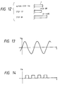
- the AC voltage used herein is, as shown in Fig. 13, a voltage continuously varying within certain limits and with a certain cycle period.
- the intermittent voltage means as shown in Fig. 14, a voltage repeating generation of a voltage value and intermission with a certain cycle period.
- the piezoelectric actuator 1 is normal, it has a considerably high insulation resistance, so that the voltage of the power supply circuit P1 applied through the transistor Q4 provides the comparator C with a high divided voltage through the diode D2 and the resistors R1, R2, R3.
- the insulation of the piezoelectric actuator 1 is destructed by the operation thereof under a high humidity condition, the upper terminal of said actuator is equivalently grounded.
- the comparator C when the transistor Q4 is turned on, the voltage applied to the comparator C becomes considerably lower, in comparison with that in the normal state, at the junction between the resistors R1, R2 is grounded. When the voltage at said junction is lower than a predetermined value, the comparator C provides the CPU with a signal indicating an abnormality in the insulation.
- the diode D2 is provided for protecting the transistor Q4 from destruction by inverse voltage application and the power supply circuit P1 from destruction, by the high voltage from the power supply circuit P2 when the transistor 05 is turned on for driving the piezoelectric actuator 1 as will be explained later.
- the resistor R1 is unnecessary in the normal state, but is provided for preventing thermal destruction caused by direct grounding of the transistor Q4 and the diode D2 in case the piezoelectric actuator 1 shows destruction of insulation.
- the surge absorber 42 has a property of showing an infinite resistance while the voltage applied between the terminals is within several hundred volts, and being shortcircuited when the voltage becomes higher.
- the surge absorber 42 connected parallel to the piezoelectric actuator 1, serves to protect the peripheral circuits from a high voltage generated by the actuator itself.
- Said surge absorber 42 do not influence said circuits in any manner in the normal state, but absorbes, by shortcircuiting, a voltage as high as tens of thousand volts eventually generated by a shock given to the camera, thereby preventing the destruction of the transistor Q4 etc. for which resistance to such high voltage cannot be expected.
- a piezoelectric member shows pyroelectric effect when heat is given thereto.
- the piezoelectric actuator 1 when given heat, the piezoelectric actuator 1 generates a voltage.
- the function for absorbing the voltage generated by such pyroelectric effect will be explained in the following.
- the transistors Q9, Q11 are turned on to dissipate therein the charge generated by pyroelectric effect in the piezoelectric actuator 1.
- Such pyroelectric charge absorbing routine is required not only in the shutter release routine, but may also be conducted at suitable timings such as during the film winding, immediately after the activation of the power supply circuit P1 or immediately before the termination of function thereof. Also the shortcircuited state may be continued while the power supply circuit P1 is activated and the piezoelectric actuator 1 is not driven, as long as the base current in the transistors Q9, Q11 does not affect the consumption of power of the battery 40.
- the piezoelectric actuator is driven, succeeding to the above-mentioned shortcircuit by the transistors Q9, Q11, in the following manner.
- the transistor Q8 is turned on, thereby applying the high voltage of the power supply circuit P2 to the upper terminal of the piezoelectric actuator through the transistor Q5.
- the output voltage of said power supply circuit P2 has to be the recommended working voltage (rated voltage) according to the operating specifications of the piezoelectric actuator, namely such voltage that does not cause destruction of the piezoelectric actuator upon repeated applications. In the present embodiment it is assumed that said recommended working voltage coincides with the driving voltage of the lamp 43.
- the piezoelectric actuator 1 is driven through the resistor R4, in order to avoid thermal destruction of the transistor Q5.
- the rated voltage is the voltage obtained from the power supply circuit Q2.
- the piezoelectric actuator 1 momentarily extends in the longitudinal direction thereof, whereby generated is a driving force, which causes the operations already explained in relation to Fig. 2.
- the CPU can recognize that the voltage application from the power supply circuit P2 failed. In such case the piezoelectric actuator 1 is driven again with a higher voltage.
- the transistor Q10 is turned on to apply the output voltage of the power supply circuit P3 to the piezoelectric actuator.
- a resistor R5 is serially connected, as in the case of the transistor Q5.
- the voltage used for such re-driving is the absolute maximum rated voltage of the piezoelectric actuator 1 or a somewhat lower voltage. Stated differently, the applied voltage does not exceed a level beyond which the destruction of the piezoelectric actuator 1 may arise.
- the re-driving is conducted with the voltage from the power supply circuit P3, which is higher than that from the power supply circuit P2, but such re-driving may also be conducted with the same voltage obtained from the power supply circuit P2. It is also possible to drive the actuator for a certain number of times with the rated voltage and then with the maximum permissible voltage.
- the transistors Q11, Q12 are turned on to apply an inverse potential through a transistor Q7, whereby the piezoelectric actuator 1 contracts in the opposite direction. Also in this state the lever 4 shown in Fig. 2 follows the end face of the actuator, without forming a gap thereto.
- the transistors Q5, Q9 are conducted by the transistors Q5, Q9. Through these operations the amount of displacement of the piezoelectric actuator 1 is almost doubled, and the resulting acceleration is accordingly increased. Also said transistor Q7 is provided with a serial resistor R6 for preventing thermal destruction.
- Figs. 3 to 9 are flow charts showing the control sequences of the CPU.
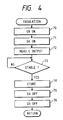
- Fig. 4 is a flow chart of the insulation state detecting routine in the step 53, of which details will be explained in the following:
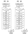
- Figs. 5A and 5B are flow charts showing two examples of the dehumidification routine in the step 64.
- the piezoelectric actuator is extended in the longitudinal direction by a voltage application, while, in the routine shown in Fig. 5B, the actuator is contracted in said direction by an inverse voltage application.
- Step 90 turns off the transistor Q9, and the sequence returns to the step 50 to repeat the above-explained sequence.
- Step 160 turns off the transistor Q11, and the sequence then returns to the step 50 for repeating the above-explained sequence.
- the charging time has to be selected at a level not inducing a displacement in the piezoelectric actuator 1, since, otherwise, the mechanical system shown in Fig. 2 is actuated during the dehumidification.
- the sequence shown in Fig. 5B does not affect the mechanical system as the piezoelectric actuator contracts.
- the repeating frequency and the number N of repetition have to be determined strictly from the experimental data on the moisture resistance of the piezoelectric actuator to be used, but in general a drive for several ten milliseconds with a frequency of several kHz.
- N, N′ are maintained constant regardless of the humidity, but they may be varied according to the humidity.
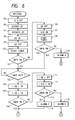
- Figs. 6 and 7 are flow charts of a release routine shown in the step 61, in which:
- step 101 identifies that the switch 16 is not turned on, namely if the leading curtain system has not properly functioned, there is executed the following sequence:
- the voltage application from the power supply circuit P3 is to obtain the maximum displacement of the piezoelectric actuator 1. Since the applied voltage is close to the absolute maximum rated voltage, such voltage, if always used, may undesirably affect the durability of the piezoelectric actuator. Said voltage is therefore used only in such abnormal state;
- the above-explained routine causes the piezoelectric actuator 1 to contract, so that larger displacement and acceleration can be obtained in combination with the extension of the actuator starting from the step 98.
- a similar inverse voltage applying routine may be applied to the piezoelectric actuator 2 for obtained larger displacement and acceleration therefrom.
- Fig. 9 is a flow chart showing an example of routine for improving the response of the piezoelectric actuator, by causing a small vibration in the actuator with a frequency close to the mechanical resonance point thereof, thereby achieving a faster displacement in the succeeding main drive.
- This routine is similar to the dehumidification routine shown in Fig. 5, but is different in the interval of operations and in the duration. This routine is executed also between the steps 97 and 98:
- the charging time has to be selected at a level not causing displacement of the piezoelectric actuator 1, since, otherwise, the mechanical system shown in Fig. 2 is actuated during this preparatory routine.
- the repeating frequency and the number N of repetition have to be exactly determined from the response, based on the resonance characteristics of the piezoelectric actuator to be used, but in general a drive for several milliseconds with a frequency of several kHz is sufficient. Though not explained in detail, a similar process is applicable also the piezoelectric actuator 2.
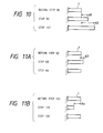
- Figs. 10, 11 and 12 illustrate the states of extension/contraction of the piezoelectric actuator 1 in the foregoing routines.
- Fig. 10 shows the states of the actuator 1 in the normal driving method shown in Fig. 6.
- the piezoelectric actuator 1 In a stationary state up to the step 98, the piezoelectric actuator 1 has a length illustrated at the top.
- a displacement A1 is obtained by the application of the output voltage of the power supply circuit P2 in the step 99. If said displacement A1 is insufficient for driving the mechanical system, the output voltage of the power supply circuit P3 is applied to the actuator 1 to generate therein a displacement A2, larger than A1, in the step 107.
- the present invention is featured by the utilization of the change in displacement and the resulting acceleration.
- Fig. 11A shows the displacements of the piezoelectric actuator 1 during the dehumidification routine shown in Fig. 5A.
- Fig. 11B shows the displacements of the actuator 1 during the dehumidification routine shown in Fig. 5B.
- Fig. 12 shows the states of the piezoelectric actuator 1 when the extension after contraction is utilized for driving the mechanical system, as explained in Fig. 8.
- the actuator having the original length up to the step 130, contracts by B1 by the inverse voltage application in the step 131, and then extends by A1 from the original length, by the voltage application in the step 99.
- the sum of the displacements B1 and A1 is utilized for driving the mechanical system.
- the dehumidification in the present embodiment is executed when the half-stroke switch is turned on, but it may also be conducted in response to the closing of an unrepresented main switch. Furthermore, it may be executed in response to the closing of an unrepresented dehumidification switch, to be closed by the depression of an unrepresented dehumidification button.
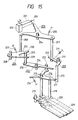
- FIG. 15 a second embodiment of the present invention shown in Fig. 15, in which the driving device for piezoelectric actuator of the present invention is applied to a shutter control device.
- This device is composed by addition of a mechanism of the present invention to the aforementioned configuration shown in Fig. 23, and the components equivalent to those in Fig. 23 are represented by same numbers.
- the piezoelectric actuator 201, levers 209, 219 and leading curtain 220 are identical with those in Fig. 23, but levers 223, 226 are provided for giving an impact force to said piezoelectric actuator 1.
- the end 206 of the lever 203 serves not only to receive the extension of the actuator for opening the leading shutter curtain but also to provide the actuator with an impact force.
- the lever 223, rotatable about a shaft 224, is provided thereon with a pin 225, which is positioned between ends 229, 230 of the lever 226 and does not interfere with said lever 226.
- Said lever 226 is rotatable about a shaft 228 and is biased by a spring 227.
- the end 230 of the lever 226 has a shoulder, as shown in Fig. 15, in a base portion 231, with which engages an end portion 208 extended newly from the lever 203.
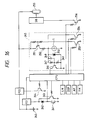
- Fig. 16 is a block diagram of an electrical circuit for driving the mechanism shown in Fig. 15. The function of said circuit will be explained in the following.
- a battery 240 powers power supply circuits P21, P22.
- the power supply circuit P1 releases an output voltage of about 5 V, for a control circuit including a CPU.
- the power supply circuit P2 releases an output voltage of about 200 V for driving the piezoelectric actuator 201 and also for driving a discharge tube 255 connected to a strobe circuit SB.
- the function of the power supply circuit P21 is controlled by a half-stroke switch 241 linked with an unrepresented shutter button of the camera and the on-off state of a transistor 243 driven by the CPU.
- the state of the half-stroke switch 241 is also transmitted to the CPU.
- a diode 242 is inserted between the transistor 243 and the switch 241 in order to distinguish the on-states thereof. In such configuration, after the half-stroke switch 241 is turned off by the termination of actuation of the shutter button, the transistor 243 remains turned on for a predetermined period, thereby extending the function state of the camera.
- a light metering circuit LM enters an object luminance signal to the CPU.
- a display circuit DSP provides shutter time information to be controlled, and various alarm signals, in visual or acoustic manner, based on signals from the CPU.
- An aperture control circuit AP controls a lens diaphragm to an appropriate aperture, base on a signal from the CPU.
- a film sensitivity signal reading circuit FM reads film sensitivity data, provided on a film cartridge in an already known manner, and sends said data to the CPU.
- the output voltage of the power supply circuit P22 is supplied to the strobe circuit SB, of which discharge tube 255 emits flash light by the activation of a transistor 256 by the CPU when the shutter is opened.
- An upper terminal of the piezoelectric actuator 1 is given the output voltage of the power supply circuit P22 through a transistor 251 and a resistor 252. Said transistor 251 is controlled by a transistor 253 driven by the CPU. Said upper terminal of the piezoelectric actuator 201 is clamped by a Zenar diode 250 and is further connected, through resistors 247, 249 and a capacitor 248, to a transistor 246. Also the piezoelectric actuator 201 is grounded through a transistor 254, which is used for dissipating, immediately before the drive of the actuator, the charge accumulated therein until said drive.
- the power supply circuit P21 starts power supply to activate the CPU, which then calculates an appropriate exposure condition, based on the input signals from the light metering circuit LM and the film sensitivity signal detection circuit FM. The result of said calculation is displayed by the display circuit DSP, and an alarm is given in addition, if said condition is undesirable.
- the transistor 244 is activated to accumulate the electric power from the power supply circuit P22 into an unrepresented capacitor, for driving the discharge tube 255.
- the end 206 of the lever 203 hits the piezoelectric actuator 201 to generate therein a voltage, which is clamped by the Zenar diode 250 whereby the transitor 246 is turned on for a predetermined period by the capacitor 248.
- the resistor 247 is provided for discharging the capacitor 248, while the resistor 249 is provided for preventing the erroneous function of the transistor.
- the CPU upon confirming the timing of completion of opening of the leading curtain by the turning-on of the transistor 246, turns on the transistor 256 to activate the strobe circuit SB for effecting light emission from the discharge tube 255.
- the CPU can also display the signal indicating the completion of opening of the leading curtain, through the display circuit DSP.
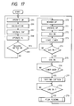
- Fig. 17 is a flow chart showing an example of shutter sequence.
- Figs. 16 and 17 the voltage generated by the piezoelectric actuator is fetched by the CPU and utilized for the subsequent process.
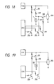
- Figs. 18 and 19 show another configuration in which the voltage from the piezoelelectric actuator is directly applied to the strobe circuit SB by a hardware modification.
- the voltage from the piezoelectric actuator 201 is transmitted to the strobe circuit SB through a transistor 261 which can be intermittently controlled by the CPU.
- components equivalent in function to those in Fig. 16 are represented by same numbers.
- the transistor 261 is turned on.
- the voltage generated by said actuator is directly applied, through the transistor 260, to the discharge tube 255.
- Said voltage sometimes reaching the level of several tens of thousand volts, is sufficient for initiating the discharge in the tube 255.
- the control by the CPU can be dispensed with.
- the activation of the transistor 260 after the voltage application to the piezoelectric actuator 201 is to prevent that the discharge tube 255 is eventually activated by the output voltage of the power supply circuit P22 prior to the proper timing.
- the output voltage of the power supply circuit P22 is lower than the triggering voltage of the discharge tube 255, there may be employed a direct connection as shown in Fig. 19, thus dispensing with the transistor 261.
- a third embodiment of the present invention applied to a shutter control mechanism as shown in Fig. 20, which illustrates a state after completion of shutter charging.
- Shafts 301 - 311 and positioning pins 329, 330 are fixed on an unrepresented shutter base plate.
- a charging lever 314 is rotatably mounted on the shaft 301 and is clockwise biased by a spring S1.
- a leading blade drive lever 315 is rotatably mounted on the shaft 304 and is anticlockwise biased by a spring S2.
- a leading hook 316 is rotatably mounted on the shaft 303 and is clockwise biased by a spring S3.
- a leading hook engaging lever 317 is rotatably mounted on the shaft 302 and is anticlockwise biased by a spring S4.
- a leading inertia lever 318 is mounted rotatably on the shaft 305 and is anticlockwise biased by a spring S5.
- a trailing blade driving lever 319 is rotatably mounted on the shaft 306 and is anticlockwise biased by a spring S6.
- a trailing hook 320 is rotatably mounted on the shaft 307 and is anticlockwise biased by a spring S7.
- a trailing hook engaging lever 321 is rotatably mounted on the shaft 309 and is clockwise biased by a spring S8.
- a trailing inertia lever 322 is rotatably mounted on the shaft 308 and is clockwise based by a spring S9.
- a leading drive arm 325 is rotatably mounted on the shaft 304 and is connected to a pin 315b fixed on the leading drive lever 315.
- a leading auxiliary arm 326 is rotatably mounted on the shaft 310, and constitutes a parallel link mechanism, in combination with the leading drive arm 325 and a leading blade 312.
- a trailing drive arm 328 is rotatably mounted on the shaft 306 and is connected to a pin 319b fixed on the trailing driver lever 319.
- a trailing auxiliary arm 327 is rotatably mounted on the shaft 311, and constitutes a parallel link mechanism in combination with the trailing drive arm 328 and a trailing blade 313.
- a laminate piezoelectric device 323 for the leading shutter blade is mounted on a mounting member 323a fixed on the unrepresented shutter base plate.
- a laminate piezoelectric device 324 for the trailing shutter blade is mounted on a mounting member 324a fixed on said base plate.
- said device 323 momentarily generates an extension, thereby hitting the leading inertia lever 318, which thus rotates clockwise about the shaft 305 against the biasing force of the spring S5.
- a pin 318a fixed on the leading inertia lever 318 collides with an arm 316a of the leading hook 316, thereby rotating said leading hook 316 anticlockwise against the biasing force of the spring S3.
- leading hook 316 As a result of rotation of said leading hook 316, a folded portion 316b thereof is disengaged from a finger 315a of the leading drive lever 315, which therefore rotates anticlockwise under the biasing force of the spring S2. As a result of said rotation, the leading shutter blade 312 connected to the pin 315b of said lever 315 moves in a direction C, thereby initiating the exposure of an image frame 329.
- leading hook 316 continues to rotate anticlockwise against the biasing force of the spring S3.
- leading hook 316 returns by clockwise rotation under the biasing force of the spring S3, but the leading hook 316 stops at a solid-lined position in Fig. 21, because the pin 316c thereof engages with the shoulder 317b of the leading hook engaging lever 317, as shown in Fig. 21.
- a pin 322a fixed on the trailing inertia lever 322 collides with an arm 320a of the trailing hook 320, thereby rotating said trailing hook 320 clockwise against the biasing force of the spring S7.
- a folded portion 320b thereof is disengaged from a finger 319a of the trailing drive lever 319, which therefore rotates anticlockwise under the biasing force of the spring S6.
- a lever 331 mounted on an unrepresented camera body moves in a direction A and pushes an arm 314a of the charging lever 314, which thus rotates anticlockwise against the biasing force of the spring S1.
- leading shutter blade 312 and the trailing shutter blade 313 are charged in a direction opposite to C, in a mutually overlapping state so as that the image frame 329 is not exposed.
- the fingers 315a, 319a of the leading and trailing driver levers 315, 319 pass through positions capable of respectively engaging with the folded portions 316b, 320b of the leading and trailing hooks 316, 320.
- the arm 315c of the leading drive lever 315 pushes the pin 317c fixed on the leading hook engaging lever 317, which therefore rotates clockwise against the biasing force of the spring S4.
- the pin 316c of the leading hook 316 and the shoulder 317b of the leading hook engaging lever 317 are disengaged. Therefore the leading hook 316 rotates clockwise under the biasing force of the spring S3, and an arm 316d of said hook 316 stops at a position in impingement with the pin 329. In this position the finger 315a of the leading drive lever 315 can engage with the folded portion 316b of the leading hook 316.
- the lever 331 After reaching this state, the lever 331 returns in a direction opposite to A. Therefore the charging lever 314 rotates clockwise under the biasing force of the spring S1, and the leading drive lever 315 and the trailing drive lever 319 rotate anticlockwise under the biasing forces of the springs S2, S6. Since the leading hook 316 and the trailing hook 320 have already returned to engageable positions as explained above, the leading drive lever 315 and the trailing drive lever 319 are respectively stopped by said leading hook 316 and trailing hook 320, whereby the state shown in Fig. 20 is restored.
- the leading hook engaging lever 317 and the trailing hook engaging lever 321 are provided for the following reason.
- the extension of the laminate piezoelectric devices 323, 324 obtained by voltage application is in the order of 0.01 mm.
- the leading hook 316 and the trailing hook 320 in their returning motions under the biasing forces of the springs S3, S7 will collide with the leading and trailing drive levers 315, 319 as indicated by chain lines in Figs. 21 and 22, whereby the shutter time may fluctuate.
- leading hook engaging lever 317 and the trailing hook engaging lever 321 have the function of securing gaps t3, t4 between the rotating trajectories of the leading drive lever 315 and the trailing drive lever 319 after disengagement thereof and the leading and trailing hooks 316, 320.
Landscapes
- Physics & Mathematics (AREA)
- General Physics & Mathematics (AREA)
- Shutters For Cameras (AREA)
- Camera Bodies And Camera Details Or Accessories (AREA)
- General Electrical Machinery Utilizing Piezoelectricity, Electrostriction Or Magnetostriction (AREA)
- Apparatuses For Generation Of Mechanical Vibrations (AREA)
Claims (19)
- Vorrichtung zum Steuern der Belichtungszeit eines Verschlusses, indem zuerst die Verrastung eines voreilenden Verschlußvorhangs (17; 312) - nachstehend "vorderer Verschlußvorhang" genannt - freigegeben und nach Verstreichen einer vorbestimmten Zeit die Verrastung eines nachlaufenden Verschlußvorhangs (37; 313) - nachstehend "hinterer Verschlußvorhang" genannt - freigegeben wird, umfassend:ein erstes und ein zweites piezoelektrisches Schichtbauelement (1, 2; 323, 324), die jeweils bei Anlegen einer Spannung eine mechanische Verformung erzeugen;eine erste mechanische Einrichtung (4-14; 315 - 318) zum Freigeben der Verrastung des vorderen Verschlußvorhangs, ansprechend auf die mechanische Verformung des ersten piezoelektrischen Schichtbauelements; undeine zweite mechanische Einrichtung (24-34; 319 - 322) zum Freigeben der Verrastung des hinteren Verschlußvorhangs, ansprechend auf die mechanische Verformung des zweiten piezoelektrischen Schichtbauelements.
- Vorrichtung nach Anspruch 1, bei der die erste mechanische Einrichtung aufweist:ein erstes Antriebskraftgewinnungsglied (4; 318) zum Erhalten einer Antriebskraft zum Freigeben der Verrastung des vorderen Verschlußvorhangs, ansprechend auf die Verformung des ersten piezoelektrischen Schichtbauelements; undein erstes Vorspannglied (5; S5) zum Vorspannen des ersten Antriebskraftgewinnungsgliedes in Richtung auf eine sich verformende Fläche des ersten piezoelektrischen Schichtbauelements;wobei die zweite mechanische Einrichtung aufweist:ein zweites Antriebskraftgewinnungsglied (24; 322) zum Erhalten einer Antriebskraft zum Freigeben der Verrastung des hinteren Verschlußvorhangs, ansprechend auf die Verformung des zweiten piezoelektrischen Schichtbauelements; undein zweites Vorspannglied (25, S9) zum Vorspannen des zweiten Antriebskraftgewinnungsglieds in Richtung auf eine sich verformende Fläche des zweiten piezoelektrischen Schichtbauelements.
- Vorrichtung nach Anspruch 1, weiterhin umfassend:ein erstes und ein zweites Verrastungsglied (335, 328) zum Verrasten des vorderen bzw. des hinteren Verschlußvorhangs;ein erstes Rückstellsperrglied (217) zum Verhindern des Rückkehrens des ersten Verrastungsglieds in die Verrastungsstellung, nachdem es aus der Verrastung freigegeben wurde; undein zweites Rückstellsperrglied (321) zum Verhindern, daß das zweite Verrastungsglied in die Verrastungsstellung zurückkehrt, nachdem es aus der Verrastung gelöst wurde;wobei die erste mechanische Einrichtung aufweist:ein erstes Verrastungsfreigabeglied (316) zum Freigeben der Verrastung des ersten Verrastungsglieds, ansprechend auf die Verformung des ersten piezoelektrischen Schichtbauelements; undein erstes Antriebsglied (315) zum Antreiben des vorderen Verschlußvorhangs, wenn das erste Verrastungsfreigabeglied die Verrastung des ersten Verrastungsglieds löst;und wobei die zweite mechanische Einrichtung aufweist:ein zweites Verrastungsfreigabeglied (320) zum Lösen der Verrastung des zweiten Verrastungsglieds, ansprechend auf die Verformung des zweiten piezoelektrischen Schichtbauelements; undein zweites Antriebsglied (319) zum Antreiben des hinteren Verschlußvorhangs, wenn das zweite Verrastungsfreigabeglied die Verrastung des zweiten Verrastungsglieds löst.
- Vorrichtung nach Anspruch 3, weiterhin umfassend:
eine Spanneinrichtung (314), die den vorderen Verschlußvorhang in den Verrastungszustand mit dem ersten Verrastungsglied und den hinteren Verschlußvorhang in den Verrastungszustand mit dem zweiten Verrastungsglied bringt. - Vorrichtung nach einem vorhergehenden Anspruch, umfassend eine Spannungsanlegeeinrichtung (46, 47) zum Anlegen einer Spannung an das erste piezoelektrische Bauelement und zum Anlegen einer Spannung an das zweite piezoelektrische Bauelement.
- Vorrichtung nach Anspruch 5, bei der die Spannungsanlegeeinrichtung aufweist:eine erste Spannungsanlegeeinrichtung (46) zum vorübergehenden Anlegen einer Spannung an das erste piezoelektrische Schichtbauelement, um die erste mechanische Einrichtung zu veranlassen, die Verrastung des vorderen Verschlußvorhangs freizugeben in Abhängigkeit der mechanischen Verformung des ersten piezoelektrischen Schichtbauelements, die sich aus dem vorübergehenden Anlegen der Spannung ergibt; undeine zweite Spannungsanlegeeinrichtung (47) zum vorübergehenden Anlegen einer Spannung an das zweite piezoelektrische Schichtbauelement, um die zweite mechanische Einrichtung zu veranlassen, die Verrastung des hinteren Verschlußvorhangs zu lösen in Abhängigkeit der mechanischen Verformung des zweiten piezoelektrischen Schichtbauelements, die sich aus dem vorübergehenden Anlegen der Spannung ergibt.
- Vorrichtung nach Anspruch 5, umfassend:eine Detektiereinrichtung (16; 36; 323, 324) zum Feststellen, ob der vordere und der hintere Verschlußvorhang abgelaufen sind;wobei die Spannungsanlegeeinrichtung dazu ausgebildet ist, den vorderen und den hinteren Verschlußvorhang ablaufen zu lassen, indem die Spannungen an das erste und das zweite piezoelektrische Schichtbauelement angelegt werden, um dadurch die mechanische Verformung in ihnen hervorzurufen und so die Verrastungen des vorderen und des hinteren Verschlußvorhangs freizugeben, und das Anlegen der Spannungen beendet wird, wenn die Detektiereinrichtung feststellt, daß die Verschlußvorhänge abgelaufen sind.
- Vorrichtung nach Anspruch 5, umfassend eine Steuereinrichtung (CPU) zum Steuern der Spannungsanlegeeinrichtung beim Anlegen einer Spannung an das erste piezoelektrische Schichtbauelement und anschließend an das zweite piezoelektrische Schichtbauelement.
- Vorrichtung nach einem der Ansprüche 1 bis 5, weiterhin umfassend eine Einrichtung (16, 36; 323, 324), die auf die Bewegung des vorderen Verschlußvorhangs oder des hinteren Verschlußvorhangs anspricht, um das Beendigen des Anlegens der Spannung an das erste piezoelektrische Schichtbauelement oder das zweite piezoelektrische Schichtbauelement zu steuern.
- Vorrichtung nach einem vorhergehenden Anspruch, wobei der jedes von dem ersten und dem zweiten piezoelektrischen Schichtbauelement mit zwei Elektroden ausgestattet ist und die Vorrichtung außerdem eine Kurzschlußeinrichtung (Q9, Q11; 254) aufweist, welche die zwei Elektroden sowohl des ersten als auch des zweiten piezoelektrischen Schichtbauelements zu einer vorbestimmten Zeit kurzschließt, während zwischen die zwei Elektroden keine Spannung gelegt wird.
- Vorrichtung nach Anspruch 10, vorgesehen in einer Kamera, bei der ein Auslöseschalter (SW), ansprechend auf das Drücken einer Auslösetaste, geschlossen wird, um einen Belichtungsvorgang einzuleiten;
wobei die vorbestimmte Zeit die Zeit des Schliessens des Auslöseschalters ist. - Vorrichtung nach einem der Ansprüche 5 bis 11, umfassend:eine Anzeigeeinrichtung (DSP);eine Beleuchtungseinrichtung (EL) zum Beleuchten der Anzeigeeinrichtung;eine Energiequelle (P2) zum Einspeisen elektrischer Energie in die Spannungsanlegeeinrichtung und die Beleuchtungseinrichtung.
- Vorrichtung nach Anspruch 12, bei der die Beleuchtungseinrichtung eine Elektrolumineszenz-Einrichtung aufweist.
- Vorrichtung nach einem der Ansprüche 5 bis 13, fähig für den Einsatz einer Blitzlichteinrichtung, wobei die Spannungsanlegeeinrichtung betreibbar ist, um an die Blitzlichteinrichtung eine Spannung anzulegen.
- Vorrichtung nach einem vorhergehenden Anspruch, umfassend eine Spannungserzeugungseinrichtung (P1-P3; P22) zum Erzeugen einer Spannung, die an den ersten und den zweiten piezoelektrischen Aktuator gelegt wird.
- Vorrichtung nach Anspruch 15, weiterhin umfassend:
eine Überspannungsabsorbiereinrichtung (42), die parallel zu dem ersten und dem zweiten piezoelektrischen Bauelement geschaltet ist und im Normalzustand eine Kennlinie hoher Impedanz zeigt, jedoch eine Kennlinie niedriger Impedanz bezüglich einer Spannungsspitze zeigt, die von den piezoelektrischen Bauelementen erzeugt wird, wenn diese einen Stoß erhalten. - Vorrichtung nach Anspruch 15 oder 16, bei der die Spannungserzeugungseinrichtung aufweist:eine erste Spannungserzeugungseinrichtung (P2) zum Erzeugen einer ersten Spannung, die an das erste und das zweite piezoelektrische Schichtbauelement angelegt wird, wobei das Anlegen der ersten Spannung die mechanische Verformung in dem ersten und dem zweiten piezoelektrischen Schichtbauelement in einem ausreichendem Maß hervorruft, um die Verrastungen der jeweiligen Verschlußvorhänge freizugeben;eine zweite Spannungserzeugungseinrichtung (P1, Q4) zum Erzeugen einer zweiten Spannung, die in dem ersten und dem zweiten piezoelektrischen Schichtbauelement Verformungen hervorruft, die keine Freigabe der Verrastungen der jeweiligen Verschlußvorhänge verursachen;wobei die zweite Spannung an das erste und das zweite piezoelektrische Schichtbauelement gelegt wird, bevor die erste Spannung angelegt wird.
- Vorrichtung nach Anspruch 17, bei der die zweite Spannungserzeugungseinrichtung dazu ausgebildet ist, ein Spannungssignal zu erzeugen, welche eine kleine Schwingung in dem ersten und dem zweiten piezoelektrischen Schichtbauelement bei einer Frequenz verursacht, die in der Nähe deren mechanischer Resonanzstelle liegt.
- Bildaufnahmevorrichtung mit einer Vorrichtung nach einem der vorhergehenden Ansprüche.
Priority Applications (4)
| Application Number | Priority Date | Filing Date | Title |
|---|---|---|---|
| EP95202707A EP0696068A3 (de) | 1991-03-12 | 1992-03-11 | Treiber für piezoelektrisches Stellglied und Kontrollvorrichtung für den Verschluss, die eine piezoelektrische Vorrichtung benutzt. |
| EP95202709A EP0696070A3 (de) | 1991-03-12 | 1992-03-11 | Treiber für piezoelektrisches Stellglied und Kontrollvorrichtung für den Verschluss, die eine piezoelektrische Vorrichtung benutzt. |
| EP95202708A EP0696069A3 (de) | 1991-03-12 | 1992-03-11 | Treiber für piezoelektrisches Stellglied und Kontrollvorrichtung für den Verschluss, die eine piezoelektrische Vorrichtung benutzt. |
| EP95202710A EP0696821A3 (de) | 1991-03-12 | 1992-03-11 | Treiber für piezoelektrisches Stellglied und Kontrollvorrichtung für den Verschluss, die eine piezoelektrische Vorrichtung benutzt. |
Applications Claiming Priority (20)
| Application Number | Priority Date | Filing Date | Title |
|---|---|---|---|
| JP3045301A JP2970006B2 (ja) | 1991-03-12 | 1991-03-12 | 圧電アクチュエータの駆動装置 |
| JP45301/91 | 1991-03-12 | ||
| JP72157/91 | 1991-03-13 | ||
| JP3072157A JPH04284430A (ja) | 1991-03-13 | 1991-03-13 | 圧電アクチュエータの駆動装置 |
| JP49439/91 | 1991-03-14 | ||
| JP3049439A JPH04284431A (ja) | 1991-03-14 | 1991-03-14 | 圧電アクチュエータを用いた駆動装置 |
| JP78355/91 | 1991-03-19 | ||
| JP78356/91 | 1991-03-19 | ||
| JP07835591A JP3189151B2 (ja) | 1991-03-19 | 1991-03-19 | 圧電アクチュエータの駆動装置 |
| JP3078356A JPH04291244A (ja) | 1991-03-19 | 1991-03-19 | 圧電アクチュエータの駆動装置 |
| JP83664/91 | 1991-03-22 | ||
| JP3083664A JP3013485B2 (ja) | 1991-03-22 | 1991-03-22 | シャッタ制御装置 |
| JP81128/91 | 1991-03-22 | ||
| JP3081128A JPH04294335A (ja) | 1991-03-22 | 1991-03-22 | 圧電アクチュエータの駆動装置 |
| JP87470/91 | 1991-03-27 | ||
| JP3087469A JPH05323417A (ja) | 1991-03-27 | 1991-03-27 | シャッタ制御装置 |
| JP3087470A JPH05323418A (ja) | 1991-03-27 | 1991-03-27 | シャッタ制御装置 |
| JP87471/91 | 1991-03-27 | ||
| JP87469/91 | 1991-03-27 | ||
| JP3087471A JP3013486B2 (ja) | 1991-03-27 | 1991-03-27 | シャッタ制御装置 |
Related Child Applications (8)
| Application Number | Title | Priority Date | Filing Date |
|---|---|---|---|
| EP95202708A Division EP0696069A3 (de) | 1991-03-12 | 1992-03-11 | Treiber für piezoelektrisches Stellglied und Kontrollvorrichtung für den Verschluss, die eine piezoelektrische Vorrichtung benutzt. |
| EP95202709.2 Division-Into | 1992-03-11 | ||
| EP95202708.4 Division-Into | 1992-03-11 | ||
| EP95202709A Division EP0696070A3 (de) | 1991-03-12 | 1992-03-11 | Treiber für piezoelektrisches Stellglied und Kontrollvorrichtung für den Verschluss, die eine piezoelektrische Vorrichtung benutzt. |
| EP95202707.6 Division-Into | 1992-03-11 | ||
| EP95202710A Division EP0696821A3 (de) | 1991-03-12 | 1992-03-11 | Treiber für piezoelektrisches Stellglied und Kontrollvorrichtung für den Verschluss, die eine piezoelektrische Vorrichtung benutzt. |
| EP95202710.0 Division-Into | 1992-03-11 | ||
| EP95202707A Division EP0696068A3 (de) | 1991-03-12 | 1992-03-11 | Treiber für piezoelektrisches Stellglied und Kontrollvorrichtung für den Verschluss, die eine piezoelektrische Vorrichtung benutzt. |
Publications (3)
| Publication Number | Publication Date |
|---|---|
| EP0508599A2 EP0508599A2 (de) | 1992-10-14 |
| EP0508599A3 EP0508599A3 (en) | 1993-02-24 |
| EP0508599B1 true EP0508599B1 (de) | 1996-12-11 |
Family
ID=27579955
Family Applications (5)
| Application Number | Title | Priority Date | Filing Date |
|---|---|---|---|
| EP92302057A Expired - Lifetime EP0508599B1 (de) | 1991-03-12 | 1992-03-11 | Treiber für ein piezoelektrisches Stellglied und Kontrollvorrichtung für den Verschluss, die eine piezoelektrische Vorrichtung benutzt |
| EP95202709A Withdrawn EP0696070A3 (de) | 1991-03-12 | 1992-03-11 | Treiber für piezoelektrisches Stellglied und Kontrollvorrichtung für den Verschluss, die eine piezoelektrische Vorrichtung benutzt. |
| EP95202707A Withdrawn EP0696068A3 (de) | 1991-03-12 | 1992-03-11 | Treiber für piezoelektrisches Stellglied und Kontrollvorrichtung für den Verschluss, die eine piezoelektrische Vorrichtung benutzt. |
| EP95202710A Withdrawn EP0696821A3 (de) | 1991-03-12 | 1992-03-11 | Treiber für piezoelektrisches Stellglied und Kontrollvorrichtung für den Verschluss, die eine piezoelektrische Vorrichtung benutzt. |
| EP95202708A Withdrawn EP0696069A3 (de) | 1991-03-12 | 1992-03-11 | Treiber für piezoelektrisches Stellglied und Kontrollvorrichtung für den Verschluss, die eine piezoelektrische Vorrichtung benutzt. |
Family Applications After (4)
| Application Number | Title | Priority Date | Filing Date |
|---|---|---|---|
| EP95202709A Withdrawn EP0696070A3 (de) | 1991-03-12 | 1992-03-11 | Treiber für piezoelektrisches Stellglied und Kontrollvorrichtung für den Verschluss, die eine piezoelektrische Vorrichtung benutzt. |
| EP95202707A Withdrawn EP0696068A3 (de) | 1991-03-12 | 1992-03-11 | Treiber für piezoelektrisches Stellglied und Kontrollvorrichtung für den Verschluss, die eine piezoelektrische Vorrichtung benutzt. |
| EP95202710A Withdrawn EP0696821A3 (de) | 1991-03-12 | 1992-03-11 | Treiber für piezoelektrisches Stellglied und Kontrollvorrichtung für den Verschluss, die eine piezoelektrische Vorrichtung benutzt. |
| EP95202708A Withdrawn EP0696069A3 (de) | 1991-03-12 | 1992-03-11 | Treiber für piezoelektrisches Stellglied und Kontrollvorrichtung für den Verschluss, die eine piezoelektrische Vorrichtung benutzt. |
Country Status (3)
| Country | Link |
|---|---|
| US (2) | US5371427A (de) |
| EP (5) | EP0508599B1 (de) |
| DE (1) | DE69215734T2 (de) |
Families Citing this family (9)
| Publication number | Priority date | Publication date | Assignee | Title |
|---|---|---|---|---|
| US5371427A (en) * | 1991-03-12 | 1994-12-06 | Nikon Corporation | Driver for piezoelectric actuator and shutter control device utilizing piezoelectric device |
| JPH0880075A (ja) * | 1994-08-31 | 1996-03-22 | Nikon Corp | アクチュエータ内蔵機器 |
| DE19640108C1 (de) * | 1996-09-28 | 1998-01-02 | Univ Magdeburg Tech | Piezoelektrischer Antriebsmodul |
| JP3866888B2 (ja) * | 1999-10-28 | 2007-01-10 | 株式会社リコー | 撮像装置 |
| JP4401975B2 (ja) * | 2004-02-10 | 2010-01-20 | パナソニック株式会社 | 監視カメラ |
| US8324783B1 (en) | 2012-04-24 | 2012-12-04 | UltraSolar Technology, Inc. | Non-decaying electric power generation from pyroelectric materials |
| DE102012209965A1 (de) * | 2012-06-14 | 2013-12-19 | Robert Bosch Gmbh | Verfahren zum Betreiben eines Ventils |
| WO2020218226A1 (ja) * | 2019-04-25 | 2020-10-29 | 株式会社フジキン | 圧電素子の劣化検知回路を備えた駆動装置及び劣化検知方法 |
| CN113671772B (zh) * | 2021-07-28 | 2022-07-26 | 南京航空航天大学 | 一种单相压电驱动的可变光阑装置 |
Family Cites Families (22)
| Publication number | Priority date | Publication date | Assignee | Title |
|---|---|---|---|---|
| US3742492A (en) * | 1971-01-11 | 1973-06-26 | D Proctor | Transducer drive circuit and signal generator |
| US3921015A (en) * | 1974-08-01 | 1975-11-18 | Branson Ultrasonics Corp | High voltage transient protection means as for piezoelectric transducers |
| US4093885A (en) * | 1976-03-19 | 1978-06-06 | Ampex Corporation | Transducer assembly vibration sensor |
| US4104657A (en) * | 1977-07-18 | 1978-08-01 | Eastman Kodak Company | Piezoelectric electronic shutter control for cameras |
| JPS5717936A (en) * | 1980-07-07 | 1982-01-29 | Canon Inc | Shutter controlled by electromagnet |
| JPS57172425U (de) * | 1981-04-23 | 1982-10-30 | ||
| DE3147803C2 (de) * | 1981-12-03 | 1985-05-30 | Kodak Ag, 7000 Stuttgart | Photographischer Verschluß mit einer piezoelektrischen Zündvorrichtung |
| JPS60149034A (ja) * | 1984-09-07 | 1985-08-06 | Olympus Optical Co Ltd | 自動調光式ストロボの動作表示装置 |
| US4689516A (en) * | 1985-05-02 | 1987-08-25 | Kabushiki Kaisha Toshiba | Position adjustment device with a piezoelectric element as a lock mechanism |
| JPS62186237A (ja) * | 1986-02-12 | 1987-08-14 | Minolta Camera Co Ltd | バイモルフ駆動素子を有するカメラ |
| US4811044A (en) * | 1986-08-12 | 1989-03-07 | Minolta Camera Kabushiki Kaisha | Shutter actuating device |
| US4760351A (en) * | 1986-08-22 | 1988-07-26 | Northern Illinois University | Multiple oscillator device having plural quartz resonators in a common quartz substrate |
| JPS63201635A (ja) * | 1987-02-18 | 1988-08-19 | Minolta Camera Co Ltd | バイモルフによつて駆動されるシヤツタ−と閃光発光手段を備えたカメラ |
| JPS63237044A (ja) * | 1987-03-25 | 1988-10-03 | Minolta Camera Co Ltd | 電歪シヤツタ−駆動装置 |
| JPS63262634A (ja) * | 1987-04-21 | 1988-10-28 | Minolta Camera Co Ltd | カメラのバイモルフ駆動式シヤツタ−装置 |
| US4920373A (en) * | 1987-06-04 | 1990-04-24 | Minolta Camera Kabushiki Kaisha | Device for driving shutter |
| JPS6434621A (en) * | 1987-07-27 | 1989-02-06 | Nippon Telegraph & Telephone | Flexible clamping device |
| JPH01118824A (ja) * | 1987-11-02 | 1989-05-11 | Stanley Electric Co Ltd | カメラ内蔵のフラッシュ発光装置 |
| JPS6477036A (en) * | 1988-07-21 | 1989-03-23 | Minolta Camera Kk | Camera equipped with camera-shake detection device |
| JP2536114B2 (ja) * | 1989-01-18 | 1996-09-18 | トヨタ自動車株式会社 | 圧電素子の駆動装置 |
| JPH0831635B2 (ja) * | 1989-05-12 | 1996-03-27 | 富士電機株式会社 | ピエゾアクチュエータの駆動電源装置 |
| US5371427A (en) * | 1991-03-12 | 1994-12-06 | Nikon Corporation | Driver for piezoelectric actuator and shutter control device utilizing piezoelectric device |
-
1992
- 1992-03-09 US US07/849,096 patent/US5371427A/en not_active Expired - Fee Related
- 1992-03-11 EP EP92302057A patent/EP0508599B1/de not_active Expired - Lifetime
- 1992-03-11 EP EP95202709A patent/EP0696070A3/de not_active Withdrawn
- 1992-03-11 EP EP95202707A patent/EP0696068A3/de not_active Withdrawn
- 1992-03-11 EP EP95202710A patent/EP0696821A3/de not_active Withdrawn
- 1992-03-11 EP EP95202708A patent/EP0696069A3/de not_active Withdrawn
- 1992-03-11 DE DE69215734T patent/DE69215734T2/de not_active Expired - Fee Related
-
1994
- 1994-10-04 US US08/317,746 patent/US5678106A/en not_active Expired - Fee Related
Also Published As
| Publication number | Publication date |
|---|---|
| DE69215734D1 (de) | 1997-01-23 |
| EP0696070A2 (de) | 1996-02-07 |
| EP0696070A3 (de) | 1998-04-01 |
| EP0696069A2 (de) | 1996-02-07 |
| US5678106A (en) | 1997-10-14 |
| EP0508599A3 (en) | 1993-02-24 |
| EP0696821A3 (de) | 1998-03-11 |
| EP0696821A2 (de) | 1996-02-14 |
| EP0696069A3 (de) | 1998-03-04 |
| US5371427A (en) | 1994-12-06 |
| DE69215734T2 (de) | 1997-04-03 |
| EP0696068A2 (de) | 1996-02-07 |
| EP0696068A3 (de) | 1998-03-04 |
| EP0508599A2 (de) | 1992-10-14 |
Similar Documents
| Publication | Publication Date | Title |
|---|---|---|
| EP0508599B1 (de) | Treiber für ein piezoelektrisches Stellglied und Kontrollvorrichtung für den Verschluss, die eine piezoelektrische Vorrichtung benutzt | |
| US4084167A (en) | Flash and camera device | |
| JPS582827A (ja) | フラツシユカメラ装置 | |
| US4214827A (en) | Automatic focus control camera | |
| WO2005039252A2 (en) | Battery saving flash charger control | |
| JP3927659B2 (ja) | 電子機器およびストロボ装置 | |
| US4884090A (en) | Piezoelectric actuating device | |
| US7049760B2 (en) | Camera flash circuit using a piezoelectric transformer to trigger firing of the camera flash tube | |
| JPS6333128B2 (de) | ||
| US4112447A (en) | Flash and camera device | |
| JP3120864B2 (ja) | フラッシュ装置の充電制御装置 | |
| US6091906A (en) | Flash device | |
| US4310230A (en) | Apparatus for preventing malfunction of an electric shutter device | |
| US4181417A (en) | Shutter operation control device for a photographic camera | |
| JP3189151B2 (ja) | 圧電アクチュエータの駆動装置 | |
| US4281912A (en) | Control circuit for camera or motor drive device | |
| US4497563A (en) | Programmed automatic exposure control | |
| JPH04284431A (ja) | 圧電アクチュエータを用いた駆動装置 | |
| US4370042A (en) | Ready-to-flash condition indicating device for a camera | |
| JPS589223Y2 (ja) | 同録式小型映画撮影機の異状検出装置 | |
| JPH04291244A (ja) | 圧電アクチュエータの駆動装置 | |
| JPH04284430A (ja) | 圧電アクチュエータの駆動装置 | |
| JPH04294335A (ja) | 圧電アクチュエータの駆動装置 | |
| US4748462A (en) | Starting arrangement for flash device | |
| RU1797719C (ru) | Реле времени кинопроектора |
Legal Events
| Date | Code | Title | Description |
|---|---|---|---|
| PUAI | Public reference made under article 153(3) epc to a published international application that has entered the european phase |
Free format text: ORIGINAL CODE: 0009012 |
|
| AK | Designated contracting states |
Kind code of ref document: A2 Designated state(s): DE FR GB |
|
| PUAL | Search report despatched |
Free format text: ORIGINAL CODE: 0009013 |
|
| AK | Designated contracting states |
Kind code of ref document: A3 Designated state(s): DE FR GB |
|
| 17P | Request for examination filed |
Effective date: 19930811 |
|
| 17Q | First examination report despatched |
Effective date: 19950216 |
|
| GRAH | Despatch of communication of intention to grant a patent |
Free format text: ORIGINAL CODE: EPIDOS IGRA |
|
| GRAH | Despatch of communication of intention to grant a patent |
Free format text: ORIGINAL CODE: EPIDOS IGRA |
|
| GRAA | (expected) grant |
Free format text: ORIGINAL CODE: 0009210 |
|
| RHK1 | Main classification (correction) |
Ipc: H01L 41/04 |
|
| AK | Designated contracting states |
Kind code of ref document: B1 Designated state(s): DE FR GB |
|
| DX | Miscellaneous (deleted) | ||
| REF | Corresponds to: |
Ref document number: 69215734 Country of ref document: DE Date of ref document: 19970123 |
|
| ET | Fr: translation filed | ||
| PLBE | No opposition filed within time limit |
Free format text: ORIGINAL CODE: 0009261 |
|
| 26N | No opposition filed | ||
| PGFP | Annual fee paid to national office [announced via postgrant information from national office to epo] |
Ref country code: DE Payment date: 20000306 Year of fee payment: 9 |
|
| PGFP | Annual fee paid to national office [announced via postgrant information from national office to epo] |
Ref country code: GB Payment date: 20000308 Year of fee payment: 9 |
|
| PGFP | Annual fee paid to national office [announced via postgrant information from national office to epo] |
Ref country code: FR Payment date: 20000310 Year of fee payment: 9 |
|
| PG25 | Lapsed in a contracting state [announced via postgrant information from national office to epo] |
Ref country code: GB Free format text: LAPSE BECAUSE OF NON-PAYMENT OF DUE FEES Effective date: 20010311 |
|
| GBPC | Gb: european patent ceased through non-payment of renewal fee |
Effective date: 20010311 |
|
| PG25 | Lapsed in a contracting state [announced via postgrant information from national office to epo] |
Ref country code: FR Free format text: LAPSE BECAUSE OF NON-PAYMENT OF DUE FEES Effective date: 20011130 |
|
| REG | Reference to a national code |
Ref country code: FR Ref legal event code: ST |
|
| PG25 | Lapsed in a contracting state [announced via postgrant information from national office to epo] |
Ref country code: DE Free format text: LAPSE BECAUSE OF NON-PAYMENT OF DUE FEES Effective date: 20020101 |