EP0507989A2 - Machine électrique à enroulement à bobines - Google Patents
Machine électrique à enroulement à bobines Download PDFInfo
- Publication number
- EP0507989A2 EP0507989A2 EP91118533A EP91118533A EP0507989A2 EP 0507989 A2 EP0507989 A2 EP 0507989A2 EP 91118533 A EP91118533 A EP 91118533A EP 91118533 A EP91118533 A EP 91118533A EP 0507989 A2 EP0507989 A2 EP 0507989A2
- Authority
- EP
- European Patent Office
- Prior art keywords
- winding coil
- winding
- pole core
- machine
- clamping part
- Prior art date
- Legal status (The legal status is an assumption and is not a legal conclusion. Google has not performed a legal analysis and makes no representation as to the accuracy of the status listed.)
- Granted
Links
- 238000004804 winding Methods 0.000 title claims abstract description 57
- 125000006850 spacer group Chemical group 0.000 claims description 7
- 230000000284 resting effect Effects 0.000 claims description 4
- 238000001816 cooling Methods 0.000 description 2
- 230000000694 effects Effects 0.000 description 1
- 238000011156 evaluation Methods 0.000 description 1
- 238000009434 installation Methods 0.000 description 1
- 230000002441 reversible effect Effects 0.000 description 1
Images


Classifications
-
- H—ELECTRICITY
- H02—GENERATION; CONVERSION OR DISTRIBUTION OF ELECTRIC POWER
- H02K—DYNAMO-ELECTRIC MACHINES
- H02K3/00—Details of windings
- H02K3/46—Fastening of windings on the stator or rotor structure
- H02K3/52—Fastening salient pole windings or connections thereto
- H02K3/521—Fastening salient pole windings or connections thereto applicable to stators only
- H02K3/522—Fastening salient pole windings or connections thereto applicable to stators only for generally annular cores with salient poles
-
- H—ELECTRICITY
- H02—GENERATION; CONVERSION OR DISTRIBUTION OF ELECTRIC POWER
- H02K—DYNAMO-ELECTRIC MACHINES
- H02K11/00—Structural association of dynamo-electric machines with electric components or with devices for shielding, monitoring or protection
- H02K11/20—Structural association of dynamo-electric machines with electric components or with devices for shielding, monitoring or protection for measuring, monitoring, testing, protecting or switching
- H02K11/25—Devices for sensing temperature, or actuated thereby
Definitions
- the invention relates to an electrical machine having winding coils according to the preamble of claim 1.
- a machine is known from DD-A-96 123.
- the clamping parts are designed as elbows, the two legs of which are approximately at right angles to one another and are curved in themselves. With one leg, the elbows are inserted between the pole core and the winding coil plugged onto it, and with the other leg they engage under the winding coil on the side lying towards the free end of the pole core. With their angle tip, the angle pieces are locked behind a projection formed on the pole core.
- the invention has for its object to develop an electrical machine of the generic type so that the winding space available on the pole cores can be used in the radial direction as optimally as possible.
- the arrangement of the clamping parts on the end faces of the pole cores enables two to be opposed to one another provide holding arms extending in the circumferential direction of the machine on the clamping parts.
- a particularly good clamping effect can be achieved in that the contour of the side of the clamping part facing the winding coil is adapted to the course of the winding coil.
- the wall part of the clamping part which is in contact with the winding coil is designed to be flexible.
- the required flexibility can be achieved in that the clamping part is hollow and the wall part lying against the winding coil is slotted, in particular is provided with a separating slot which is continuous in the axial direction of the clamping part.
- the wall part is divided into two wall arms, which have a corresponding mobility due to the material elasticity.
- the locking of the clamping part on the pole core is possible in a structurally simple manner in that at least one bore located within the region of the pole core covered by the winding coil is provided on the end face of the pole core and at least one with the bore on the wall side of the clamping part adjacent to the pole core lockable knobs is resiliently arranged.
- sensors in particular for detecting the winding temperature, can be arranged on it.
- the connecting lines of such sensors can be routed freely to the outside through the free space existing between the wall arms of the clamping part.
- brackets are provided at least on one long side of the winding coil.
- spacers inserted between the winding coils of the reversing poles and the winding coils applied to the main poles are expediently used as holders, these spacers being provided with an attachment which has a receiving groove and engages under the coil longitudinal side are.
- the spacers are provided with openings extending in the longitudinal direction of the machine.
- FIG. 1 shows the housing-free stand of an electrical machine with an integrated pole core 2.
- a prefabricated winding coil 3 is plugged onto this pole core 2.
- the windings 4 of the winding coil 3 are formed in a circular arc on the end faces 5 of the pole core 2. This creates a cavity between the flat end face 5 of the pole core 2 and the circular arc 6 of the innermost turn 4, into which a clamping part 7, which is advantageously made of plastic, is used to secure the winding coil 3 on the pole core 2.
- This clamping part 7 has two wall arms 8 and 9 adapted in their outer contour to the circular arc shape of the innermost turn 4. These wall arms 8 and 9 are formed on a flat wall 10 of the clamping part 7 resting on the end face 5 of the respective pole core 2. On the side facing the stator bore 11, the clamping part 7 also has two holding arms 12 which extend in the opposite direction in the circumferential direction of the machine and engage under the winding coil 3 on the side facing the stator bore.
- a resilient arm 14 is formed by incisions 13, on which a knob 16 provided with a run-on slope 15 is formed. With this knob 16, the clamping part 7 engages in a bore 17 provided in the pole core 2 and is thereby secured.
- receiving niches 18 are formed on the wall arms 8 and 9, into which sensors, for example temperature sensors, can be inserted. These sensors come on the winding coil 3 to the system and can therefore record the temperature of the coil very well.
- the sensors are connected via connecting lines 19 to an evaluation point arranged centrally on the machine or outside it. From the point of use of the sensor or sensors on the wall arm 8 or 9, the connecting lines 19 are led out through the free space between the wall arms 8 and 9 to the stator bore. If the connecting lines 19 then also have to be routed from one machine side to the other machine side, then they can be held below the longitudinal side of the respective winding coil 3 by means of appropriate holders 20.
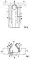
- FIG 5 serves as brackets 20 for the connecting lines 19 lugs 25 which are formed on spacers 24 which are inserted between the winding coils 21 of the main poles 22 and the winding coils 3 of the reversing poles 23 of the machine.
- lugs 25 which are formed on spacers 24 which are inserted between the winding coils 21 of the main poles 22 and the winding coils 3 of the reversing poles 23 of the machine.
- a receiving groove 26 is provided, into which the connecting lines 19 are inserted.
- the spacers 24 are also provided with openings 27 extending in the longitudinal direction of the machine in order to allow the cooling air to flow through as freely as possible.
- the winding coils 3 are pushed onto the pole core 2 of the reversing poles 23. Thereafter, the clamping parts 7 are inserted from the stator bore side into the cavity existing between the end faces 5 of the pole cores 2 and the circular arc 6 of the innermost turn 4.
- the wall arms 8 and 9 can adapt accordingly because of the separating slot 28 between them and the elasticity of their material even with existing dimensional deviations of the individual arcs 6, so that a good one Installation of these wall arms 8 and 9 on the rounding of the turns 4 is given. With the flat wall 10, the clamping part 7 slides along the end face 5 of the pole core 2.
- the knob 16 meets with its bevel 15 on the edge of the pole core and slides over it, since the knob can deflect due to the resilient nature of the arm 14.
- the clamping part 7 is pushed into the cavity until the knob 16 is congruent in front of the bore 17. Due to the spring action of the arm 14, the knob 16 is pressed into the bore 17 and lies with its round outer contour against the bore 17.
- the clamping part 7 is securely locked to the pole core 2 and is able to hold the winding coil securely on the pole core by means of its holding arms 12 which engage under the winding coil 3.
Landscapes
- Engineering & Computer Science (AREA)
- Power Engineering (AREA)
- Microelectronics & Electronic Packaging (AREA)
- Iron Core Of Rotating Electric Machines (AREA)
- Manufacture Of Motors, Generators (AREA)
Applications Claiming Priority (2)
| Application Number | Priority Date | Filing Date | Title |
|---|---|---|---|
| DE4111320A DE4111320A1 (de) | 1991-04-08 | 1991-04-08 | Wicklungsspulen aufweisende elektrische maschine |
| DE4111320 | 1991-04-08 |
Publications (3)
| Publication Number | Publication Date |
|---|---|
| EP0507989A2 true EP0507989A2 (fr) | 1992-10-14 |
| EP0507989A3 EP0507989A3 (fr) | 1994-02-16 |
| EP0507989B1 EP0507989B1 (fr) | 1995-07-26 |
Family
ID=6429059
Family Applications (1)
| Application Number | Title | Priority Date | Filing Date |
|---|---|---|---|
| EP91118533A Expired - Lifetime EP0507989B1 (fr) | 1991-04-08 | 1991-10-30 | Machine électrique à enroulement à bobines |
Country Status (3)
| Country | Link |
|---|---|
| US (1) | US5220229A (fr) |
| EP (1) | EP0507989B1 (fr) |
| DE (3) | DE4111320A1 (fr) |
Cited By (1)
| Publication number | Priority date | Publication date | Assignee | Title |
|---|---|---|---|---|
| WO2000051222A1 (fr) * | 1999-02-25 | 2000-08-31 | Abb Ab | Procede et machine electrique rotative |
Families Citing this family (3)
| Publication number | Priority date | Publication date | Assignee | Title |
|---|---|---|---|---|
| DE10002485A1 (de) * | 2000-01-21 | 2001-08-02 | Mannesmann Sachs Ag | Wickelkörper zur Aufnahme einer Wicklung für einen elektro-magneto-mechanischen Wandler sowie elektro-magneto-mechanischer Wandler |
| US20020180577A1 (en) * | 2001-01-19 | 2002-12-05 | Mannesmann Sachs Ag | Winding body for receiving a winding for an electromagnetomechanical converter and electromagnetomechanical converter |
| JP4737054B2 (ja) * | 2006-11-30 | 2011-07-27 | トヨタ自動車株式会社 | 絶縁部材およびステータ |
Citations (4)
| Publication number | Priority date | Publication date | Assignee | Title |
|---|---|---|---|---|
| US2709763A (en) * | 1953-08-20 | 1955-05-31 | Westinghouse Electric Corp | Coil support for dynamo-electric machine |
| FR2383541A1 (fr) * | 1977-03-09 | 1978-10-06 | Bbc Brown Boveri & Cie | Pole matrice pour une machine electrique |
| US4629918A (en) * | 1985-09-26 | 1986-12-16 | General Electric Company | Spacer to prevent coil shift |
| US4633114A (en) * | 1985-09-26 | 1986-12-30 | General Electric Company | Motor coil retention apparatus |
Family Cites Families (11)
| Publication number | Priority date | Publication date | Assignee | Title |
|---|---|---|---|---|
| DE155539C (fr) * | ||||
| US886561A (en) * | 1906-09-04 | 1908-05-05 | Nat Brake & Electric Co | Coil-support. |
| CH459342A (de) * | 1967-01-18 | 1968-07-15 | Oerlikon Maschf | Gleichstrommaschine |
| DD96123A1 (fr) * | 1972-04-20 | 1973-03-12 | ||
| SU843104A1 (ru) * | 1979-08-27 | 1981-06-30 | Предприятие П/Я А-7376 | Устройство дл креплени катушкиК пОлюСу |
| EP0064105B1 (fr) * | 1981-05-06 | 1985-10-23 | AMP INCORPORATED (a New Jersey corporation) | Stator d'un moteur électrique et son procédé de fabrication |
| SU1030918A1 (ru) * | 1982-04-07 | 1983-07-23 | Ленинградское Электромашиностроительное Объединение "Электросила" Им.С.М.Кирова | Полюс электрической машины |
| DE3244844A1 (de) * | 1982-12-03 | 1984-06-07 | Heidolph Elektro Gmbh & Co Kg | Elektromotor |
| GB2172444B (en) * | 1985-03-09 | 1988-08-17 | Asmo Co Ltd | Stator for an electric motor |
| DE3519901C2 (de) * | 1985-06-04 | 1995-02-16 | Papst Motoren Gmbh & Co Kg | Kollektorloser Gleichstrommotor |
| US4847527A (en) * | 1988-12-09 | 1989-07-11 | Emerson Electric Co. | Hall effect assembly for mounting to stators |
-
1991
- 1991-04-08 DE DE4111320A patent/DE4111320A1/de not_active Withdrawn
- 1991-10-30 EP EP91118533A patent/EP0507989B1/fr not_active Expired - Lifetime
- 1991-10-30 DE DE59106093T patent/DE59106093D1/de not_active Expired - Fee Related
- 1991-11-13 DE DE9114145U patent/DE9114145U1/de not_active Expired - Lifetime
-
1992
- 1992-01-23 US US07/824,598 patent/US5220229A/en not_active Expired - Fee Related
Patent Citations (4)
| Publication number | Priority date | Publication date | Assignee | Title |
|---|---|---|---|---|
| US2709763A (en) * | 1953-08-20 | 1955-05-31 | Westinghouse Electric Corp | Coil support for dynamo-electric machine |
| FR2383541A1 (fr) * | 1977-03-09 | 1978-10-06 | Bbc Brown Boveri & Cie | Pole matrice pour une machine electrique |
| US4629918A (en) * | 1985-09-26 | 1986-12-16 | General Electric Company | Spacer to prevent coil shift |
| US4633114A (en) * | 1985-09-26 | 1986-12-30 | General Electric Company | Motor coil retention apparatus |
Non-Patent Citations (2)
| Title |
|---|
| PATENT ABSTRACTS OF JAPAN vol. 3, no. 6 (E-85)22. Januar 1979 & JP-A-53 133 702 ( TOKYO DENKI K.K. ) 21. November 1978 * |
| SOVIET INVENTIONS ILLUSTRATED Section EI, Week E15, 26. Mai 1982 Derwent Publications Ltd., London, GB; Class X11, AN E3410 & SU-A-843 104 (GORDENKO N S) 30. Juni 1981 * |
Cited By (1)
| Publication number | Priority date | Publication date | Assignee | Title |
|---|---|---|---|---|
| WO2000051222A1 (fr) * | 1999-02-25 | 2000-08-31 | Abb Ab | Procede et machine electrique rotative |
Also Published As
| Publication number | Publication date |
|---|---|
| DE4111320A1 (de) | 1992-10-15 |
| EP0507989B1 (fr) | 1995-07-26 |
| EP0507989A3 (fr) | 1994-02-16 |
| DE9114145U1 (de) | 1992-08-13 |
| US5220229A (en) | 1993-06-15 |
| DE59106093D1 (de) | 1995-08-31 |
Similar Documents
| Publication | Publication Date | Title |
|---|---|---|
| EP0255512B1 (fr) | Connecteur electrique (adaptateur) | |
| DE2401037C2 (de) | Rohrstück für Reinigungsmaschinen, insbesondere für Staub- oder Flüssigkeitssauggeräte | |
| DE2837486C3 (de) | Sonde zur Wirbelstromprüfung von Rohren | |
| DE3914936A1 (de) | Endgehaeuse fuer mehrpolige elektrische steckverbinder | |
| EP0170274A2 (fr) | Instrument pour nettoyer les organes de couplage des guides d'ondes lumineuses | |
| DE3601469C2 (fr) | ||
| DE2736932C3 (de) | Halterung für Stator-Wickelköpfe elektrischer Maschinen | |
| EP0507989B1 (fr) | Machine électrique à enroulement à bobines | |
| EP0212158B1 (fr) | Dispositif palpeur de profil | |
| DE7915432U1 (de) | Teleskopierbarer fuehrungsstiel fuer haushaltsgeraete | |
| DE4228305A1 (de) | Führungsschelle für mindestens eine flexible Leitung | |
| DE2919231C2 (fr) | ||
| DE4430018A1 (de) | Elektrische Stelleinrichtung | |
| EP0786856A1 (fr) | Dispositif de commutation pour moteur à courant continu sans balais | |
| DE102018106880A1 (de) | Modularer Kontaktträger für einen Industriesteckverbinder | |
| DE19917066A1 (de) | Halterung für einen Temperatursensor | |
| EP0054115B1 (fr) | Support de fil, particulièrement pour clôtures capacitives de protection | |
| DE19638976A1 (de) | Verstellbare Stromübertragungseinrichtung für ein Staubsaugerteleskoprohr | |
| DE8909824U1 (de) | Stator | |
| DE1590617C (de) | Mit Kontaktstiften zur Aufnahme eines Dosensteckers versehener elektrischer Schal | |
| DE1514555C (de) | Aus einzelnen Isolierstoffbauteilen zusammengesetzter rohrförmiger Spulenträger | |
| DE29516288U1 (de) | Schnell und automatisch zusammensetzbare Lampenfassung | |
| DE2642185B2 (de) | Einrichtung zur Kabelhalterung | |
| CH680544A5 (fr) | ||
| DE19726836A1 (de) | Steckkontaktverbinder |
Legal Events
| Date | Code | Title | Description |
|---|---|---|---|
| PUAI | Public reference made under article 153(3) epc to a published international application that has entered the european phase |
Free format text: ORIGINAL CODE: 0009012 |
|
| AK | Designated contracting states |
Kind code of ref document: A2 Designated state(s): CH DE FR GB IT LI |
|
| PUAL | Search report despatched |
Free format text: ORIGINAL CODE: 0009013 |
|
| AK | Designated contracting states |
Kind code of ref document: A3 Designated state(s): CH DE FR GB IT LI |
|
| 17P | Request for examination filed |
Effective date: 19940322 |
|
| 17Q | First examination report despatched |
Effective date: 19940721 |
|
| GRAA | (expected) grant |
Free format text: ORIGINAL CODE: 0009210 |
|
| AK | Designated contracting states |
Kind code of ref document: B1 Designated state(s): CH DE FR GB IT LI |
|
| REF | Corresponds to: |
Ref document number: 59106093 Country of ref document: DE Date of ref document: 19950831 |
|
| GBT | Gb: translation of ep patent filed (gb section 77(6)(a)/1977) |
Effective date: 19950829 |
|
| ITF | It: translation for a ep patent filed | ||
| ET | Fr: translation filed | ||
| PLBE | No opposition filed within time limit |
Free format text: ORIGINAL CODE: 0009261 |
|
| STAA | Information on the status of an ep patent application or granted ep patent |
Free format text: STATUS: NO OPPOSITION FILED WITHIN TIME LIMIT |
|
| 26N | No opposition filed | ||
| PGFP | Annual fee paid to national office [announced via postgrant information from national office to epo] |
Ref country code: GB Payment date: 19980909 Year of fee payment: 8 |
|
| PGFP | Annual fee paid to national office [announced via postgrant information from national office to epo] |
Ref country code: CH Payment date: 19990119 Year of fee payment: 8 |
|
| PG25 | Lapsed in a contracting state [announced via postgrant information from national office to epo] |
Ref country code: GB Free format text: LAPSE BECAUSE OF NON-PAYMENT OF DUE FEES Effective date: 19991030 |
|
| PG25 | Lapsed in a contracting state [announced via postgrant information from national office to epo] |
Ref country code: LI Free format text: LAPSE BECAUSE OF NON-PAYMENT OF DUE FEES Effective date: 19991031 Ref country code: CH Free format text: LAPSE BECAUSE OF NON-PAYMENT OF DUE FEES Effective date: 19991031 |
|
| REG | Reference to a national code |
Ref country code: CH Ref legal event code: PL |
|
| GBPC | Gb: european patent ceased through non-payment of renewal fee |
Effective date: 19991030 |
|
| PGFP | Annual fee paid to national office [announced via postgrant information from national office to epo] |
Ref country code: DE Payment date: 20001218 Year of fee payment: 10 |
|
| PGFP | Annual fee paid to national office [announced via postgrant information from national office to epo] |
Ref country code: FR Payment date: 20011031 Year of fee payment: 11 |
|
| PG25 | Lapsed in a contracting state [announced via postgrant information from national office to epo] |
Ref country code: DE Free format text: LAPSE BECAUSE OF NON-PAYMENT OF DUE FEES Effective date: 20020702 |
|
| PG25 | Lapsed in a contracting state [announced via postgrant information from national office to epo] |
Ref country code: FR Free format text: LAPSE BECAUSE OF NON-PAYMENT OF DUE FEES Effective date: 20030630 |
|
| REG | Reference to a national code |
Ref country code: FR Ref legal event code: ST |
|
| PG25 | Lapsed in a contracting state [announced via postgrant information from national office to epo] |
Ref country code: IT Free format text: LAPSE BECAUSE OF NON-PAYMENT OF DUE FEES;WARNING: LAPSES OF ITALIAN PATENTS WITH EFFECTIVE DATE BEFORE 2007 MAY HAVE OCCURRED AT ANY TIME BEFORE 2007. THE CORRECT EFFECTIVE DATE MAY BE DIFFERENT FROM THE ONE RECORDED. Effective date: 20051030 |