EP0507585B1 - Verspleissen von Glasfasern - Google Patents
Verspleissen von Glasfasern Download PDFInfo
- Publication number
- EP0507585B1 EP0507585B1 EP92302911A EP92302911A EP0507585B1 EP 0507585 B1 EP0507585 B1 EP 0507585B1 EP 92302911 A EP92302911 A EP 92302911A EP 92302911 A EP92302911 A EP 92302911A EP 0507585 B1 EP0507585 B1 EP 0507585B1
- Authority
- EP
- European Patent Office
- Prior art keywords
- holding device
- end parts
- abutment
- towards
- axially aligned
- Prior art date
- Legal status (The legal status is an assumption and is not a legal conclusion. Google has not performed a legal analysis and makes no representation as to the accuracy of the status listed.)
- Expired - Lifetime
Links
- 239000013307 optical fiber Substances 0.000 title claims abstract description 42
- 230000003287 optical effect Effects 0.000 claims description 52
- 238000007526 fusion splicing Methods 0.000 claims description 23
- 230000004927 fusion Effects 0.000 claims description 20
- 239000000835 fiber Substances 0.000 abstract description 9
- 238000010304 firing Methods 0.000 abstract description 4
- 230000000712 assembly Effects 0.000 abstract description 3
- 238000000429 assembly Methods 0.000 abstract description 3
- 230000000977 initiatory effect Effects 0.000 description 6
- 238000013016 damping Methods 0.000 description 5
- 238000000034 method Methods 0.000 description 4
- 230000000694 effects Effects 0.000 description 2
- 239000000463 material Substances 0.000 description 2
- 230000015572 biosynthetic process Effects 0.000 description 1
- 230000000994 depressogenic effect Effects 0.000 description 1
- 238000010438 heat treatment Methods 0.000 description 1
- 230000004048 modification Effects 0.000 description 1
- 238000012986 modification Methods 0.000 description 1
- 230000001681 protective effect Effects 0.000 description 1
- 230000001360 synchronised effect Effects 0.000 description 1
Images
Classifications
-
- G—PHYSICS
- G02—OPTICS
- G02B—OPTICAL ELEMENTS, SYSTEMS OR APPARATUS
- G02B6/00—Light guides; Structural details of arrangements comprising light guides and other optical elements, e.g. couplings
- G02B6/24—Coupling light guides
- G02B6/255—Splicing of light guides, e.g. by fusion or bonding
- G02B6/2551—Splicing of light guides, e.g. by fusion or bonding using thermal methods, e.g. fusion welding by arc discharge, laser beam, plasma torch
Definitions
- This invention relates to effecting a fusion splice between two optical fibres, one or each of which may be a component of an optical cable, and is particularly concerned with the actual fusion splicing operation effected immediately after end parts of the two optical fibres have been prepared and positioned for fusion splicing.
- the subsequent fusion splicing operation comprises two stages which are effected in sequence.
- the end parts of the two optical fibres are heated rapidly by means of an arc struck between electrodes disposed on opposite sides of the end parts of the optical fibres to a temperature such that at least the extreme end parts of the optical fibres are in a softened state and, thereafter, during the second stage of the fusion splicing operation, the end part of one or each optical fibre is moved axially towards and against the end part of the other optical fibre to a predetermined extent and at a predetermined rate for a predetermined period of time to enable the aligned and softened end parts of the optical fibres to fuse together.
- Optical fusion splicing apparatus hitherto proposed and used to effect the actual fusion splicing operation generally operate automatically or semi-automatically and require accurately tooled equipment and complicated electronic circuitry to ensure that the period of time that ensues during initial heating of the end parts of the fibres to bring them to a softened state, the extent of axial movement of one or each end part of the fibres towards and against the other, the rate at which the end parts are caused to abut and the period of time that ensues after the softened end parts have been caused to abut will always be such that a satisfactory fusion splice between end parts of two optical fibres can be repeatedly obtained.
- such optical fibre fusion splicing apparatus is expensive.
- the quantity and fragile nature of the component parts of such splicing apparatus necessitates the provision of a strong, substantially rigid protective casing in which the component parts of the apparatus are housed, which casing, though portable, is of substantial weight.
- Such apparatus comprises:
- the apparatus is characterised in that the means controlling movement of said part of the movable holding device towards the other holding device is mechanical and comprises at least one main spring so disposed as to urge said part of the movable holding device towards said other holding device at said predetermined rate when the or each main spring is actuated by operation of said master switch, and at least one damper which controls the rate of movement of said part of the movable holding device under the action of said main spring or springs to provide a predetermined period of time sufficient to enable the arc struck between said transversely spaced electrodes to bring axially aligned end parts of two optical fibres to an appropriate softened state before the prepared and softened end faces of the end parts abut.
- the mechanical means for controlling movement of said part of the movable holding device towards the other holding device is also adapted to control limited movement of at least a part of at least one of said holding devices away from the other holding device.
- the or each damper may itself be at least one supplementary spring which is acting against the force exerted by said main spring or springs and which must be overcome by said main spring or springs.
- Alternative forms of damper that may be employed include pneumatically and hydraulically controlled pistons and spring controlled rack and pinion devices.
- the mechanical means also controls limited movement of at least a part of at least one of the holding devices away from the other holding device, preferably the two holding devices are so inter-engaged, that when said part of the movable holding device has been caused to move towards the other holding device under the action of said main spring or springs to a predetermined extent, said main spring or springs directly or indirectly causes or cause said part of the other holding device to move to a limited extent away from said movable holding device.
- the optical fibre holding devices preferably each comprise a two-part clamp for gripping an end part of an optical fibre but it is to be understood that any convenient form of device for so holding an optical fibre that relative lengthwise movement of the fibre with respect to at least a part of the device is substantially restrained may be employed.
- a typical period of time sufficient for the arc to bring the axially aligned end parts of two optical fibres to an appropriate softened state is 0.5 second; a typical period of time during which one softened end part is urged towards and against the other softened end part is 1 second and the time taken for a complete fusion splice to be effected is approximately 3 seconds.
- the improved optical fibre fusion splicing apparatus of the present invention has the very important advantage that the splicing station with its elongate support table and transversely spaced electrodes; the high voltage circuitry for striking an arc between the electrodes; and the longitudinally spaced holding devices and associated mechanical control means can be housed in a casing which is separately formed with respect to a casing housing a low voltage power source which can be electrically connected to the high voltage circuitry by a flexible electric cable.
- the casing housing the low voltage power source preferably is adapted to be clipped or otherwise supported on a belt worn by an operator and the casing housing the splicing station with its elongate table and electrodes, the high voltage circuitry, and the holding devices and associated mechanical control means can be of such a size that it can be readily held in a hand of an operator.
- the improved optical fibre splicing apparatus of the present invention may have associated with its elongate table and positioned between its transversely spaced electrodes retractable spacing means against which bodies disposed on axially aligned end parts of two optical fibres can abut so that prepared end faces of optical fibre tails protruding from the bodies are spaced apart by a distance appropriate for the formation of a fusion splice therebetween but, preferably, the improved optical fibre splicing apparatus is especially, but not exclusively, suitable for use when employing the improved method of, and the improved component for use in, positioning two optical fibres relative to one another for the purpose of effecting a fusion splice therebetween as described and illustrated in the specification filed with our co-pending British Patent Application No: GB-A-2,255,419.
- each holding device of the improved fusion splicing apparatus is a two-part clamp consisting of an abutment upstanding from the support table and, beyond and at a predetermined distance from the abutment, a spring-loaded catch for urging a one-piece collar disposed on an optical fibre against the face of the abutment remote from the other abutment, so that the collar will be directly or indirectly clamped between the abutment and the spring-loaded catch which together effectively constitute the jaws of the two-part clamp.
- the mechanical control means for controlling movement of said part of the movable two-part clamp is operatively coupled to the jaw of the clamp constituted by the upstanding abutment and the spring-loaded catch constituting the other jaw of the two-part clamp is movable with the abutment when a one-piece collar disposed on an optical fibre is directly or indirectly clamped between the abutment and the spring-loaded catch and the mechanical control means is actuated to cause the movable abutment to move towards the other of the two longitudinally spaced abutments.
- Each abutment and/or each spring-loaded catch preferably has extending lengthwise therethrough a slot which opens into one side face thereof and through which can be passed a part of an optical fibre protruding from a one-piece collar disposed on the fibre.
- the remote faces of the abutments i.e. the faces of the abutments against which one-piece collars disposed on optical fibres will be arranged to abut, and the faces of the spring-loaded catches to be urged against the opposite end faces of the collars are substantially flat and lie in planes substantially radial to the axis of a collar when clamped therebetween.
- the surface of the elongate table may have formed therein for maintaining end parts of two optical fibres in substantially axial alignment, an open-ended substantially rectilinear groove which extends over at least a part of the length of the table between and substantially normal to the transversely spaced electrodes but, preferably, the elongate table intermediate of its ends and between the electrodes has means for positive removable location on the table of a preformed substantially rigid elongate support member having an open ended substantially rectilinear optical fibre guide passage extending between the ends of the member and having, at a position intermediate of the ends of the member, a slot or aperture which intersects said guide passage and extends transversely across the width of the support member and which will be in substantially axial alignment with the electrodes.
- the locating means is an elongate depression in the surface of the elongate table centrally disposed between the ends of the table and the electrodes lie on the central transverse axis of the depression so that a support member having its transversely extending slot or aperture centrally disposed between its ends will be positively located with its transversely extending slot or aperture in alignment with the electrodes.
- the transversely spaced electrodes of the improved optical fibre fusion splicing apparatus may be retractable and constrained to move towards and away from each other in a direction substantially parallel to their axes.
- the improved optical fibre fusion splicing apparatus is suitable for use in the method of effecting an end-to-end fusion splice between two optical fibres as described in the specification of our co-pending Application No: GB-A-2,253,922.
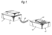
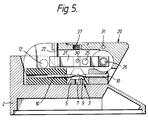
- the preferred apparatus comprises a splicing station 1 and a low voltage power source 41, the splicing station, including a pair of transversely spaced electrodes and high voltage circuitry (not shown) for striking an arc between the electrodes for fusion splicing axially aligned end parts of two optical fibres when positioned between the electrodes, being disposed in a casing 2 and the low voltage power source being housed in a casing 42 which is separately formed with respect to the casing 2.
- the low voltage power source 41 is electrically connected to the high voltage circuitry of the splicing station 1 by a flexible electric cable 45.
- the casing 42 of the low voltage power source 41 has secured to its outer surface a resilient clip 43 by means of which the casing can be supported on a belt worn by an operator.
- the casing 2 of the splicing station 1 is of such a size that it can be held in a hand of an operator.
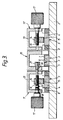
- the splicing station 1 comprises an elongate table 3 and a pair of electrodes 10 transversely spaced on opposite sides of the elongate table intermediate of its ends.
- High voltage circuitry (not shown) for striking an arc between the transversely spaced electrodes 10 is housed in the casing 2 of the splicing station 1.
- Disposed near opposite ends of the elongate table 3 are two two-part clamps 11,11′ for indirectly holding end parts of two optical fibres in axial alignment on the table with the prepared end faces of the fibres spaced a predetermined distance apart and between the transversely spaced electrodes 10.
- the elongate table 3 comprises three separately formed component parts consisting of two end parts 4 and an intermediate part 5.
- the intermediate part 5 has an uppermost surface in which is formed an open-ended rectilinear groove 7 for accommodating uncoated end parts of two optical fibres, the groove lying normal to the transversely-spaced electrodes 10.
- an upstanding slotted guide 8 At each end of each end part 4 and in axial alignment with the groove 7 in the uppermost surface of the intermediate part 5 is an upstanding slotted guide 8 for assisting in location of an optical fibre in the groove 7.
- Intermediate of the ends of the intermediate part 5 is a channel 9 which is normal to the rectilinear groove 7 and which is in alignment with the transversely-spaced electrodes 10.
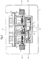
- Each two-part clamp assembly 11,11′ consists of an end part 4 of the elongate table 3 and a jaw 14 carried by a spring-loaded arm 13 mounted to pivot about a fixed main shaft 12 which is secured to the casing 2 and which extends parallel to the rectilinear groove 7 in the uppermost surface of the intermediate part 5 of the elongate table.
- the uppermost surface of the end part 4 is of a material having a low co-efficient of friction; the surface 15 of the jaw 14 which will bear against a coated optical fibre when disposed on the uppermost surface of the end part 4 is of a material having a high co-efficient of friction.
- each clamp assembly 11,11′ is in screw-threaded engagement with a spindle 16 which is rotatably mounted in the arm 13 parallel to the main shaft 12, the jaw being restrained against rotation with respect to the arm.
- a spindle 16 By rotating each spindle 16 in the appropriate direction by means of a knurled knob 17 on an end of the spindle, the jaw 14 and a coated optical fibre clamped by the jaw on the uppermost surface of the associated end part 4 can be moved with respect to the end part 4 towards or away from the common axis of the transversely-spaced electrodes 10 so that the prepared end faces of the optical fibres can be appropriately positioned relative to one another between the electrodes.
- the jaw 14 of the two-part clamp assembly 11 is urged to move to a limited extent relative to the associated end part 4 towards the two-part clamp assembly 11′ in a direction parallel to the rectilinear groove 7 in the uppermost surface of the intermediate part 5 of the elongate table 3 by a main coil spring 18 which is carried by the spindle 16 between an internal surface of the arm 13 and an adjustable stop 19 on the spindle.
- a carriage 20 Pivotally mounted on the fixed main shaft 12 between the spring-loaded arms 13 is a carriage 20 in which a lever 21 is pivotally mounted about a fixed spindle 22 which is normal to the main shaft.
- the extent of pivotal movement of the lever 21 can be determined by means of two adjustable stops 23, 24 positioned in opposite side walls of the carriage 20 so that an electrical contact 25, which is carried by but electrically insulated from the lever and which is connected by an insulated electric cable (not shown) to the control circuit of the high voltage circuitry, will abut one or other of the stops when the lever is pivoted about the spindle 22.
- the electrical contact 25 of the lever 21 is urged against the stop 23 by a damping coil spring 27 and associated damper 28 carried by a shaft 26 mounted in the carriage 20 and extending parallel to the main shaft 12.
- the lever 21 has between its ends a stud 30 which extends into a hole 29 in one side wall of the carriage 20 and which is in abutting engagement with the free end of the spindle 16 rotatably mounted in the arm 13 of the two-part clamp assembly 11, thereby, as shown in Figure 2, resisting motion of the jaw 14 under the action of the main coil spring 18 towards the two-part clamp assembly 11′.
- the main coil spring 18, the damping spring 27 and associated damper 28 and the pivotally mounted lever 21 constitute the principal components of the control mechanism of the splicing station 1.
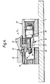
- Loading of the control mechanism to the loaded position shown in Figure 2 can be effected by means of a loading button 32 which is slidably mounted on a shaft 31 which is housed in the carriage 20 and which extends parallel to the main shaft 12. Secured to and dependant from the loading button 32 is a cranked lever 33 which near its free end has a hole through which the shaft 26 protrudes and which near its free end abuts a stop 34 at the free end of the shaft. By sliding the loading button 32 in the direction of Arrow A ( Figure 4), the control mechanism can be loaded as shown in Figure 2. Actuation of the control mechanism can be effected by depression of a firing button 35 which constitutes the master switch and is mounted on the top of the carriage 20 and which is adapted to release a stop 36 temporarily preventing extension of the damping spring 27.
- a firing button 35 which constitutes the master switch and is mounted on the top of the carriage 20 and which is adapted to release a stop 36 temporarily preventing extension of the damping spring 27.
- the carriage 20 also has immediately above the transversely extending channel 9 in the intermediate part 5 of the elongate table 3 an internally screw-threaded hole 37 in which a microscope (not shown) can be detachably connected.
- the casing 2 of the splicing station 1 has an on/ off switch 38 by means of which the electrical power must be switched on before the splicing station can be employed.
- the high voltage circuitry associated with the transversely-spaced electrodes 10 is conventional and will therefore not be described.
- the electrodes 10 may be housed in the pivotally mounted carriage 20.
- the two fibres are positioned in the rectilinear groove 7 of the elongate table 3 with their prepared end faces spaced apart between the electrodes 10 and in the transversely-extending channel 9 at a distance approximating to that appropriate for fusion splicing and the spring-loaded arms 13 are closed to cause the jaws 14 to clamp the optical fibres on the uppermost surfaces of the end parts 4.
- the jaws 14 of the two-part clamp assemblies 11,11′, and hence the optical fibres clamped by these jaws are moved towards or away from one another so that the prepared end faces of the optical fibres are adjusted to be at the required distance apart for fusion splicing, typically 50 micrometres, the end parts of the fibres being viewed through the microscope (not shown) detachably connected to the carriage 20.
- the electrical power is then switched on by means of the on/off switch 38 and the loading button 32 is slid on the shaft 31 in the direction of Arrow A ( Figure 4) to bring the control mechanism to the loaded state as shown in Figure 2.
- the master switch constituted by the firing button 35 is then depressed to actuate the control mechanism.
- the stop 36 On depression of the firing button 35, the stop 36 is released and the damping spring 27 gradually extends to reduce the force acting against the main spring 18. As the force exerted by the damping spring 27 gradually reduces to a value approximating to the force exerted on the stud 30 of the lever 21 by the main spring 18, the lever begins to pivot about the shaft 22 away from the adjustable stop 23 and towards the adjustable stop 24.
- the interruption of electrical contact between the electrical contact 25 and the adjustable stop 23 effected by pivotal movement of the lever 21 causes an arc to be initiated between the transversely-spaced electrodes 10 to bring end parts of the optical fibres to a softened state. The initiation of the arc is thus synchronised with the initiation of pivotal movement of the lever 21.
- the damped rate of pivotal movement of the lever 21, and hence the damped rate of movement of the jaw 14 of the two-part clamp assembly 11 and of the optical fibre clamped by the jaw to the associated end part 4 towards the optical fibre clamped by the jaw 14 of the two-part clamp assembly 11′ to the uppermost surface of the associated end part 4, is such that the time which elapses during the initiation of pivotal movement of the lever, the consequent initiation of movement of the jaw 14 of the two-part clamp assembly 11 and of the optical fibre clamped by the jaw to the associated end part 4, the consequent initiation of the arc and the subsequent abutment of the prepared ends of the optical fibres is a predetermined period, typically 0.5 seconds, sufficient to allow the prepared ends of the optical fibres to achieve an appropriate softened state before they abut one another.
- the power of the arc is increased to a level such that the ends of the fibres fuse together to form a substantially longitudinally continuous optical fibre.
- the arc then continues to fire for a predetermined period, sufficient to allow the surface tension of the molten fibres to correct any misalignment of the fibre axes, before being automatically extinguished.
- the time taken for a complete fusion splice to be effected by the apparatus is typically 5 seconds.
- the spliced fibres can be removed from the splicing station and mechanical protection for the fusion splice can be provided.
- the control mechanism of the splicing station 1 can then be reloaded as described for effecting of a further optical fibre splice.
Landscapes
- Physics & Mathematics (AREA)
- Engineering & Computer Science (AREA)
- Plasma & Fusion (AREA)
- General Physics & Mathematics (AREA)
- Optics & Photonics (AREA)
- Mechanical Coupling Of Light Guides (AREA)
- Seal Device For Vehicle (AREA)
Claims (9)
- Vorrichtung zur Ausführung eines Fusionsspleißens zwischen vorbereiteten und axial ausgerichteten Endteilen zweier Glasfasern, wobei die Vorrichtung folgendes aufweist:(i) eine Spleißstation (1), die einen länglichen Tisch (3) mit mindestens einer Oberfläche zum Auflegen vorbereiteter und axial ausgerichteter Endteile zweier Glasfasern und ein Paar Elektroden (10) aufweist, die transversal an gegenüberliegenden Seiten des länglichen Tisches zwischen seinen Enden beabstandet sind; und(ii) einen Hochspannungsschaltkreis zum Schlagen eines Lichtbogens zwischen den transversal beabstandeten Elektroden zum Fusionsspleißen axial ausgerichteter Endteile zweier dazwischen angeordneter Glasfasern;wobei die Spleißstation (1) an oder in der Nähe von gegenüberliegenden Enden des länglichen Tisches angeordnete Vorrichtungen (11,11') zum direkten oder indirekten Halten der Endteile zweier Glasfasern aufweist, die mit ihren in einem vorgegebenen Abstand voneinander entfernt beabstandeten, vorbereiteten Endflächen in einem Bereich zwischen den Haltevorrichtungen und zwischen den transversal beabstandeten Elektroden axial auf dem Tisch ausgerichtet worden sind, wobei mindestens ein Teil (14) mindestens einer Haltevorrichtung (11) gezwungen wird, sich in einem begrenzten Ausmaß auf die andere Haltevorrichtung hin und von ihr weg zu bewegen, und zwar in einer Richtung, die im wesentlichen parallel zu den axial ausgerichteten Endteilen zweier Glasfasern verläuft, wenn diese auf dem Tisch aufliegen, so daß, wenn der Teil der bewegbaren Haltevorrichtung gezwungen wird, sich in einem begrenzten Ausmaß hin zur anderen Haltevorrichtung zu bewegen, der Endteil in der bewegbaren Haltevorrichtung axial zum anderen Endteil bewegt werden wird; wobei die Vorrichtung einen Hauptschalter (35) zum Aktivieren des Hochspannungsschaltkreises aufweist, die Spleißstation ebenfalls Einrichtungen (18,21,27&28) zur Steuerung der Bewegung des Teils der bewegbaren Haltevorrichtung hin zur anderen Haltevorrichtung aufweist und der Hauptschalter (35) ebenfalls die Steuerungseinrichtungen aktiviert, wobei die Anordnung so ist, daß, wenn der Schalter betätigt wird, um das Schlagen eines Lichtbogens zwischen den transversal beabstandeten Elektroden hervorzurufen und um die Steuerungseinrichtungen zu aktivieren, die Geschwindigkeit der gesteuerten Bewegung des Teils der bewegbaren Haltevorrichtung hin zur anderen Haltevorrichtung so sein wird, daß zwischen dem Schlagen des Lichtbogens und dem Aneinanderstoßen der vorbereiteten Endflächen der axial ausgerichteten Endteile der Fasern eine vorgegebene Zeitdauer verstreichen wird, die dem Lichtbogen ausreicht, um die zwei Endteile in einen für das Fusionsspleißen geeigneten weichen Zustand zu bringen, und daß danach die vorbereiteten und weich gemachten Endflächen in eine aneinanderstoßende Beziehung gezwungen werden, so daß ein Fusionsspleißen zwischen den aneinanderstoßenden, axial ausgerichteten Endteilen ausgeführt werden wird, dadurch gekennzeichnet, daß die Einrichtung zur Steuerung der Bewegung des Teils (14) der bewegbaren Haltevorrichtung (11) hin zur anderen Haltevorrichtung (11') mechanisch ist und mindestens eine Hauptfeder, die so angeordnet ist, daß sie mit der vorgegebenen Geschwindigkeit den Teil der bewegbaren Haltevorrichtung hin zu der anderen Haltevorrichtung zwingt, wenn die oder jede Hauptfeder durch Betätigung des Hauptschalters (35) aktiviert ist, und mindestens einen Dämpfer (27,28) aufweist, der die Geschwindigkeit der Bewegung des Teils der bewegbaren Haltevorrichtung unter Wirkung der Hauptfeder oder der Hauptfedern steuert, um eine vorgegebene Zeitdauer zur Verfügung zu stellen, die ausreicht, um dem zwischen den transversal beabstandeten Elektroden geschlagenen Lichtbogen zu ermöglichen, axial ausgerichtete Endteile zweier Glasfasern in einen geeigneten weichen Zustand zu bringen, bevor die vorbereiteten und weich gemachten Endflächen der Endteile aneinanderstoßen.
- Vorrichtung nach Anspruch 1, dadurch gekennzeichnet, daß der Dämpfer oder mindestens einer der Dämpfer mindestens eine zusätzliche Feder (27) ist, die gegen die von der Hauptfeder oder den Hauptfedern (18) ausgeübten Kräfte wirkt und die von der Hauptfeder oder den Hauptfedern überwunden werden muß.
- Vorrichtung nach Anspruch 1 oder 2, dadurch gekennzeichnet, daß die mechanische Einrichtung zur Steuerung der Bewegung des Teils der bewegbaren Haltevorrichtung hin zur anderen Haltevorrichtung ebenfalls geeignet ist, die begrenzte Bewegung mindestens eines Teils mindestens einer Haltevorrichtung weg von der anderen Haltevorrichtung zu steuern, wobei die zwei Haltevorrichtungen so ineinandergreifen, daß, wenn unter Wirkung der Hauptfeder oder der Hauptfedern eine im Ausmaß vorgegebene Bewegung des Teils der bewegbaren Haltevorrichtung hin zur anderen Haltevorrichtung hervorgerufen worden ist, die Hauptfeder oder die Hauptfedern direkt oder indirekt eine im Ausmaß begrenzte Bewegung des Teils der anderen Haltevorrichtung weg von der bewegbaren Haltevorrichtung hervorrufen.
- Vorrichtung nach einem der Ansprüche 1 bis 3, dadurch gekennzeichnet, daß die Glasfaser-Haltevorrichtungen (11,11') jeweils eine zweiteilige Klemmvorrichtung (4,13) zum Greifen eines Endteils einer Glasfaser aufweisen.
- Vorrichtung nach Anspruch 4, dadurch gekennzeichnet, daß die oder jede Hauptfeder (18) in einem Teil (13) einer der zweiteiligen Klemmvorrichtungen (4,13) untergebracht ist und dadurch, daß der oder jeder Dämpfer (27,28) in einem Schlitten (20) untergebracht ist, der zwischen den Haltevorrichtungen (11,11') angeordnet ist und der um eine Achse schwenkbar montiert ist, die parallel zu und transversal beabstandet von den axial ausgerichteten Endteilen zweier Glasfasern verläuft, wenn diese auf dem länglichen Tisch aufliegen.
- Vorrichtung nach Anspruch 4, dadurch gekennzeichnet, daß die zweiteilige Klemmvorrichtung, die jede Haltevorrichtung bildet, aus einem aus dem Auflagetisch heraus aufrecht stehenden Anschlag und, weiter weg und in einem vorgegebenen Abstand von dem Anschlag entfernt, einer unter Federspannung stehenden Schnappvorrichtung besteht, um einen an einer Glasfaser angebrachten einstückigen Kragen gegen die von dem anderen Anschlag abgewandte Fläche des Anschlags zu zwingen, so daß der Kragen zwischen dem Anschlag und der unter Federspannung stehenden Schnappvorrichtung geklemmt wird, die zusammen wirkungsvoll die Backen der zweiteiligen Klemmvorrichtung bilden; dadurch, daß die mechanische Steuerungseinrichtung zur Steuerung der Bewegung des Teils der bewegbaren zweiteiligen Klemmvorrichtung funktionsmäßig mit der von dem aufrecht stehenden Anschlag gebildeten Backe der Klemmvorrichtung gekoppelt ist, und dadurch, daß die unter Federspannung stehende Schnappvorrichtung, die die andere Backe der zweiteiligen Klemmvorrichtung bildet, mit dem Anschlag bewegbar ist, wenn ein an einer Glasfaser angebrachter, einstückiger Kragen zwischen dem Anschlag und der unter Federspannung stehenden Schnappvorrichtung geklemmt ist und die mechanische Steuerungseinrichtung aktiviert ist, um eine Bewegung des bewegbaren Anschlags hin zum anderen der zwei längs beabstandeten Anschläge hervorzurufen.
- Vorrichtung nach einem der voranstehenden Ansprüche, dadurch gekennzeichnet, daß die Spleißstation (1) mit ihrem länglichen Tisch (3) und den transversal beabstandeten Elektroden (10), der Hochspannungsschaltkreis zum Schlagen eines Lichtbogens zwischen den Elektroden, und die längs beabstandeten Haltevorrichtungen (11,11') und die zugehörigen mechanischen Steuerungseinrichtungen (18,21,27&28) in einem Gehäuse (2) untergebracht sind, das getrennt von einem Gehäuse (42) gebildet ist, in dem eine Niederspannungsenergiequelle (41) untergebracht ist, die durch ein biegsames elektrisches Kabel (45) elektrisch mit dem Hochspannungsschaltkreis verbunden werden kann.
- Vorrichtung nach Anspruch 7, dadurch gekennzeichnet, daß das Gehäuse (42), in dem die Niderspannungsenergiequelle (41) untergebracht ist, geeignet ist, an einem von einer Bedienungsfachkraft getragenen Gürtel geklemmt oder auf andere Weise gehalten zu werden.
- Vorrichtung nach Anspruch 7 oder 8, dadurch gekennzeichnet, daß das Gehäuse (2), in dem die Spleißstation (1) mit ihrem länglichen Tisch (3) und Elektroden (10), der Hochspannungsschaltkreis und die Haltevorrichtungen (11,11') und die zugehörigen mechanischen Steuerungseinrichtungen (18,21,27&28) untergebracht sind, eine solche Größe hat, daß es ohne weiteres in der Hand einer Bedienungsfachkraft gehalten werden kann.
Applications Claiming Priority (2)
| Application Number | Priority Date | Filing Date | Title |
|---|---|---|---|
| GB919106981A GB9106981D0 (en) | 1991-04-03 | 1991-04-03 | Optical fibre splicing |
| GB9106981 | 1991-04-03 |
Publications (3)
| Publication Number | Publication Date |
|---|---|
| EP0507585A2 EP0507585A2 (de) | 1992-10-07 |
| EP0507585A3 EP0507585A3 (de) | 1992-12-02 |
| EP0507585B1 true EP0507585B1 (de) | 1996-02-28 |
Family
ID=10692585
Family Applications (1)
| Application Number | Title | Priority Date | Filing Date |
|---|---|---|---|
| EP92302911A Expired - Lifetime EP0507585B1 (de) | 1991-04-03 | 1992-04-02 | Verspleissen von Glasfasern |
Country Status (5)
| Country | Link |
|---|---|
| US (1) | US5249247A (de) |
| EP (1) | EP0507585B1 (de) |
| AT (1) | ATE134775T1 (de) |
| DE (1) | DE69208497T2 (de) |
| GB (2) | GB9106981D0 (de) |
Families Citing this family (17)
| Publication number | Priority date | Publication date | Assignee | Title |
|---|---|---|---|---|
| DE69416714T2 (de) * | 1993-05-03 | 1999-11-11 | At & T Corp., New York | Verfahren zum thermischen Verspleissen von optischen Fasern |
| CA2116934C (en) * | 1994-03-03 | 2000-08-01 | Murray R. Harman | Method for controlling the contact of optical fibers |
| JP2795167B2 (ja) * | 1994-03-29 | 1998-09-10 | 住友電気工業株式会社 | 光ファイバの融着接続機 |
| US5488683A (en) * | 1994-04-29 | 1996-01-30 | Litton Systems, Inc. | Method for splicing polarization maintaining fiber with elliptical stress member |
| SE502879C2 (sv) * | 1994-06-16 | 1996-02-12 | Ericsson Telefon Ab L M | Sätt och anordning för att skarva ihop ändar på optiska fibrer |
| US5481640A (en) * | 1994-06-27 | 1996-01-02 | Fiberlign Division Of Preformed Line Products (Canada) Ltd. | Tool for fusing optical fibers |
| US5740301A (en) * | 1994-06-27 | 1998-04-14 | Fiberlign Division Of Preformed Line Products Ltd. | Fusion splicing block with electrodes disposed on planar surface |
| US5487125A (en) * | 1994-06-28 | 1996-01-23 | At&T Corp. | Method and apparatus for fusion splicing optical fibers |
| JP2836033B2 (ja) * | 1994-08-26 | 1998-12-14 | 日本鋼管株式会社 | 金属管被覆光ファイバーケーブル接続装置 |
| GB9418878D0 (en) * | 1994-09-20 | 1994-11-09 | Bicc Plc | Optical cable fusion splice |
| DE19746080A1 (de) * | 1996-10-24 | 1998-04-30 | Siemens Ag | Verfahren sowie Vorrichtung zur Einstellung von Schweißparametern |
| US20040071414A1 (en) * | 2002-10-15 | 2004-04-15 | Fitel Interconnectivity Corp. | System, controller and method for fusion splicing at least one pair of optical fibers |
| US7004640B2 (en) * | 2003-03-24 | 2006-02-28 | Aurora Instruments, Inc. | Low profile local injection and detection system for optical fiber waveguides |
| US7070342B2 (en) * | 2003-03-24 | 2006-07-04 | Aurora Instruments, Inc. | Low profile system for joining optical fiber waveguides |
| US6984077B2 (en) * | 2003-03-25 | 2006-01-10 | Aurora Instruments, Inc. | System for joining polarization-maintaining optical fiber waveguides |
| US7090414B2 (en) * | 2003-03-25 | 2006-08-15 | Aurora Instruments, Inc. | Automatic apparatus for cleaving optical fiber waveguides |
| KR20140009355A (ko) | 2011-02-25 | 2014-01-22 | 오트로닉스, 인크 | 현장 종단 광섬유 커넥터 및 접속기 |
Citations (1)
| Publication number | Priority date | Publication date | Assignee | Title |
|---|---|---|---|---|
| GB2074338A (en) * | 1980-04-15 | 1981-10-28 | Sumitomo Electric Industries | Fusion Bonding Optical Fibres |
Family Cites Families (11)
| Publication number | Priority date | Publication date | Assignee | Title |
|---|---|---|---|---|
| GB1543187A (en) * | 1975-07-28 | 1979-03-28 | Corning Glass Works | Light transmitting fibres |
| DE3065130D1 (en) * | 1979-05-01 | 1983-11-10 | Post Office | Apparatus of joining together optical fibres |
| US4313744A (en) * | 1980-04-11 | 1982-02-02 | Sumitomo Electric Industries, Ltd. | Method and device for automatically fusing optical fibers |
| JPS59118A (ja) * | 1982-06-25 | 1984-01-05 | Nippon Telegr & Teleph Corp <Ntt> | 多心光フアイバの融着接続機 |
| DE3245229A1 (de) * | 1982-12-07 | 1984-06-07 | Siemens AG, 1000 Berlin und 8000 München | Thermisches lichtwellenleiter-schweissgeraet |
| EP0144603A3 (de) * | 1983-11-10 | 1986-06-25 | Northern Telecom Limited | Vorrichtung zum Ausrichten eines Gegenstandes auf einen Bezugspunkt |
| GB2175410A (en) * | 1985-04-03 | 1986-11-26 | Stc Plc | Optical fibre fusion splicing |
| GB8608282D0 (en) * | 1986-04-04 | 1986-05-08 | Bicc Plc | Optical fibre splicing |
| JPH01169408A (ja) * | 1987-12-21 | 1989-07-04 | Fujikura Ltd | シングルモード光ファイバ接続部の判定法 |
| US5002351A (en) * | 1988-07-05 | 1991-03-26 | Preformed Line Products Company | Fusion splicer for optical fibers |
| US5046813A (en) * | 1988-09-07 | 1991-09-10 | Fujikura Ltd. | Method and apparatus for aligning a plurality of single-fiber cables, and method of simultaneously fusion-splicing such cables |
-
1991
- 1991-04-03 GB GB919106981A patent/GB9106981D0/en active Pending
-
1992
- 1992-04-02 US US07/862,336 patent/US5249247A/en not_active Expired - Fee Related
- 1992-04-02 EP EP92302911A patent/EP0507585B1/de not_active Expired - Lifetime
- 1992-04-02 GB GB9207212A patent/GB2254935B/en not_active Expired - Fee Related
- 1992-04-02 AT AT92302911T patent/ATE134775T1/de active
- 1992-04-02 DE DE69208497T patent/DE69208497T2/de not_active Expired - Fee Related
Patent Citations (1)
| Publication number | Priority date | Publication date | Assignee | Title |
|---|---|---|---|---|
| GB2074338A (en) * | 1980-04-15 | 1981-10-28 | Sumitomo Electric Industries | Fusion Bonding Optical Fibres |
Also Published As
| Publication number | Publication date |
|---|---|
| US5249247A (en) | 1993-09-28 |
| ATE134775T1 (de) | 1996-03-15 |
| DE69208497D1 (de) | 1996-04-04 |
| GB2254935B (en) | 1994-06-29 |
| DE69208497T2 (de) | 1996-10-31 |
| EP0507585A2 (de) | 1992-10-07 |
| EP0507585A3 (de) | 1992-12-02 |
| GB9106981D0 (en) | 1991-05-22 |
| GB2254935A (en) | 1992-10-21 |
| GB9207212D0 (en) | 1992-05-13 |
Similar Documents
| Publication | Publication Date | Title |
|---|---|---|
| EP0507585B1 (de) | Verspleissen von Glasfasern | |
| US5195157A (en) | Optical fibre splicing | |
| US4736632A (en) | Optical fibre splicing | |
| US4274707A (en) | Apparatus for fusion splicing of optical fibers | |
| US5249246A (en) | Self-contained fiber splicing unit and method for splicing together optical fibers | |
| EP0246636B1 (de) | Vorrichtung zum Verschmelzen von optischen Fibern mit Polarisationserhaltung | |
| US5002351A (en) | Fusion splicer for optical fibers | |
| WO2002004998A1 (en) | Optical fiber wire holder, fused connection device, cutting device, and method of connecting optical fiber | |
| JP4772262B2 (ja) | 光学的プラグコネクタの組立のための方法,この方法を実施するための装置及びこのような方法における使用のためのプラグコネクタ | |
| GB1570032A (en) | Thermal fusion splicers for optical fibres | |
| US4548669A (en) | Light waveguide welding device | |
| US7805045B2 (en) | Optical fibre cleaving device | |
| CN112748494B (zh) | 熔接机 | |
| US20030108307A1 (en) | Optical attenuator employing a fusion splice | |
| US4255222A (en) | Apparatus for splicing thermoplastic yarns | |
| CN114769813B (zh) | 焊接装置和方法 | |
| JP3171552B2 (ja) | 光ファイバ接続装置 | |
| JP3732558B2 (ja) | 光ファイバ接続器用接続工具 | |
| US20100239214A1 (en) | Apparatus and arrangement for trimming and splicing of optical waveguides | |
| JP3278549B2 (ja) | 光ファイバ供給装置 | |
| PL134239B1 (en) | Method of and apparatus for electrically welding light propagating fibres | |
| JPH0289009A (ja) | 光ファイバクランプ機構 | |
| CN120972315A (zh) | 一种建筑电气施工用光纤熔接机 | |
| JPH01254905A (ja) | 光フアイバ心線の融着接続方法 | |
| JPS6022327B2 (ja) | 光フアイバの融着接続装置 |
Legal Events
| Date | Code | Title | Description |
|---|---|---|---|
| PUAI | Public reference made under article 153(3) epc to a published international application that has entered the european phase |
Free format text: ORIGINAL CODE: 0009012 |
|
| AK | Designated contracting states |
Kind code of ref document: A2 Designated state(s): AT BE CH DE DK ES FR GB GR IT LI LU MC NL PT SE |
|
| PUAL | Search report despatched |
Free format text: ORIGINAL CODE: 0009013 |
|
| AK | Designated contracting states |
Kind code of ref document: A3 Designated state(s): AT BE CH DE DK ES FR GB GR IT LI LU MC NL PT SE |
|
| 17P | Request for examination filed |
Effective date: 19930219 |
|
| 17Q | First examination report despatched |
Effective date: 19941018 |
|
| GRAA | (expected) grant |
Free format text: ORIGINAL CODE: 0009210 |
|
| AK | Designated contracting states |
Kind code of ref document: B1 Designated state(s): AT BE CH DE DK ES FR GR IT LI LU MC NL PT SE |
|
| PG25 | Lapsed in a contracting state [announced via postgrant information from national office to epo] |
Ref country code: AT Effective date: 19960228 Ref country code: DK Effective date: 19960228 Ref country code: BE Effective date: 19960228 Ref country code: ES Free format text: THE PATENT HAS BEEN ANNULLED BY A DECISION OF A NATIONAL AUTHORITY Effective date: 19960228 Ref country code: NL Free format text: LAPSE BECAUSE OF FAILURE TO SUBMIT A TRANSLATION OF THE DESCRIPTION OR TO PAY THE FEE WITHIN THE PRESCRIBED TIME-LIMIT Effective date: 19960228 Ref country code: CH Free format text: LAPSE BECAUSE OF FAILURE TO SUBMIT A TRANSLATION OF THE DESCRIPTION OR TO PAY THE FEE WITHIN THE PRESCRIBED TIME-LIMIT Effective date: 19960228 Ref country code: GR Free format text: LAPSE BECAUSE OF FAILURE TO SUBMIT A TRANSLATION OF THE DESCRIPTION OR TO PAY THE FEE WITHIN THE PRESCRIBED TIME-LIMIT Effective date: 19960228 Ref country code: LI Free format text: LAPSE BECAUSE OF FAILURE TO SUBMIT A TRANSLATION OF THE DESCRIPTION OR TO PAY THE FEE WITHIN THE PRESCRIBED TIME-LIMIT Effective date: 19960228 Ref country code: IT Free format text: LAPSE BECAUSE OF FAILURE TO SUBMIT A TRANSLATION OF THE DESCRIPTION OR TO PAY THE FEE WITHIN THE PRE;WARNING: LAPSES OF ITALIAN PATENTS WITH EFFECTIVE DATE BEFORE 2007 MAY HAVE OCCURRED AT ANY TIME BEFORE 2007. THE CORRECT EFFECTIVE DATE MAY BE DIFFERENT FROM THE ONE RECORDED.SCRIBED TIME-LIMIT Effective date: 19960228 |
|
| REF | Corresponds to: |
Ref document number: 134775 Country of ref document: AT Date of ref document: 19960315 Kind code of ref document: T |
|
| REF | Corresponds to: |
Ref document number: 69208497 Country of ref document: DE Date of ref document: 19960404 |
|
| PG25 | Lapsed in a contracting state [announced via postgrant information from national office to epo] |
Ref country code: MC Effective date: 19960430 Ref country code: LU Free format text: LAPSE BECAUSE OF NON-PAYMENT OF DUE FEES Effective date: 19960430 |
|
| PG25 | Lapsed in a contracting state [announced via postgrant information from national office to epo] |
Ref country code: PT Effective date: 19960528 |
|
| ET | Fr: translation filed | ||
| NLV1 | Nl: lapsed or annulled due to failure to fulfill the requirements of art. 29p and 29m of the patents act | ||
| REG | Reference to a national code |
Ref country code: CH Ref legal event code: PL |
|
| PLBE | No opposition filed within time limit |
Free format text: ORIGINAL CODE: 0009261 |
|
| STAA | Information on the status of an ep patent application or granted ep patent |
Free format text: STATUS: NO OPPOSITION FILED WITHIN TIME LIMIT |
|
| 26N | No opposition filed | ||
| PGFP | Annual fee paid to national office [announced via postgrant information from national office to epo] |
Ref country code: FR Payment date: 19970409 Year of fee payment: 6 |
|
| PGFP | Annual fee paid to national office [announced via postgrant information from national office to epo] |
Ref country code: DE Payment date: 19970414 Year of fee payment: 6 |
|
| PGFP | Annual fee paid to national office [announced via postgrant information from national office to epo] |
Ref country code: SE Payment date: 19970418 Year of fee payment: 6 |
|
| PG25 | Lapsed in a contracting state [announced via postgrant information from national office to epo] |
Ref country code: SE Free format text: LAPSE BECAUSE OF NON-PAYMENT OF DUE FEES Effective date: 19980403 |
|
| PG25 | Lapsed in a contracting state [announced via postgrant information from national office to epo] |
Ref country code: FR Free format text: THE PATENT HAS BEEN ANNULLED BY A DECISION OF A NATIONAL AUTHORITY Effective date: 19980430 |
|
| EUG | Se: european patent has lapsed |
Ref document number: 92302911.0 |
|
| PG25 | Lapsed in a contracting state [announced via postgrant information from national office to epo] |
Ref country code: DE Free format text: LAPSE BECAUSE OF NON-PAYMENT OF DUE FEES Effective date: 19990202 |
|
| REG | Reference to a national code |
Ref country code: FR Ref legal event code: ST |